EP4574064A2 - Système d'athérectomie - Google Patents
Système d'athérectomie Download PDFInfo
- Publication number
- EP4574064A2 EP4574064A2 EP25153934.2A EP25153934A EP4574064A2 EP 4574064 A2 EP4574064 A2 EP 4574064A2 EP 25153934 A EP25153934 A EP 25153934A EP 4574064 A2 EP4574064 A2 EP 4574064A2
- Authority
- EP
- European Patent Office
- Prior art keywords
- drive mechanism
- speed
- control signal
- control
- stall
- Prior art date
- Legal status (The legal status is an assumption and is not a legal conclusion. Google has not performed a legal analysis and makes no representation as to the accuracy of the status listed.)
- Pending
Links
Images


Classifications
-
- A—HUMAN NECESSITIES
- A61—MEDICAL OR VETERINARY SCIENCE; HYGIENE
- A61B—DIAGNOSIS; SURGERY; IDENTIFICATION
- A61B17/00—Surgical instruments, devices or methods
- A61B17/32—Surgical cutting instruments
- A61B17/3205—Excision instruments
- A61B17/3207—Atherectomy devices working by cutting or abrading; Similar devices specially adapted for non-vascular obstructions
- A61B17/320758—Atherectomy devices working by cutting or abrading; Similar devices specially adapted for non-vascular obstructions with a rotating cutting instrument, e.g. motor driven
-
- A—HUMAN NECESSITIES
- A61—MEDICAL OR VETERINARY SCIENCE; HYGIENE
- A61B—DIAGNOSIS; SURGERY; IDENTIFICATION
- A61B17/00—Surgical instruments, devices or methods
- A61B17/32—Surgical cutting instruments
- A61B17/3205—Excision instruments
- A61B17/3207—Atherectomy devices working by cutting or abrading; Similar devices specially adapted for non-vascular obstructions
-
- A—HUMAN NECESSITIES
- A61—MEDICAL OR VETERINARY SCIENCE; HYGIENE
- A61B—DIAGNOSIS; SURGERY; IDENTIFICATION
- A61B90/00—Instruments, implements or accessories specially adapted for surgery or diagnosis and not covered by any of the groups A61B1/00 - A61B50/00, e.g. for luxation treatment or for protecting wound edges
- A61B90/06—Measuring instruments not otherwise provided for
-
- A—HUMAN NECESSITIES
- A61—MEDICAL OR VETERINARY SCIENCE; HYGIENE
- A61B—DIAGNOSIS; SURGERY; IDENTIFICATION
- A61B17/00—Surgical instruments, devices or methods
- A61B2017/00017—Electrical control of surgical instruments
-
- A—HUMAN NECESSITIES
- A61—MEDICAL OR VETERINARY SCIENCE; HYGIENE
- A61B—DIAGNOSIS; SURGERY; IDENTIFICATION
- A61B17/00—Surgical instruments, devices or methods
- A61B2017/00017—Electrical control of surgical instruments
- A61B2017/00022—Sensing or detecting at the treatment site
- A61B2017/00075—Motion
-
- A—HUMAN NECESSITIES
- A61—MEDICAL OR VETERINARY SCIENCE; HYGIENE
- A61B—DIAGNOSIS; SURGERY; IDENTIFICATION
- A61B17/00—Surgical instruments, devices or methods
- A61B2017/00017—Electrical control of surgical instruments
- A61B2017/00115—Electrical control of surgical instruments with audible or visual output
- A61B2017/00119—Electrical control of surgical instruments with audible or visual output alarm; indicating an abnormal situation
-
- A—HUMAN NECESSITIES
- A61—MEDICAL OR VETERINARY SCIENCE; HYGIENE
- A61B—DIAGNOSIS; SURGERY; IDENTIFICATION
- A61B17/00—Surgical instruments, devices or methods
- A61B2017/00017—Electrical control of surgical instruments
- A61B2017/00132—Setting operation time of a device
-
- A—HUMAN NECESSITIES
- A61—MEDICAL OR VETERINARY SCIENCE; HYGIENE
- A61B—DIAGNOSIS; SURGERY; IDENTIFICATION
- A61B17/00—Surgical instruments, devices or methods
- A61B2017/00017—Electrical control of surgical instruments
- A61B2017/00199—Electrical control of surgical instruments with a console, e.g. a control panel with a display
-
- A—HUMAN NECESSITIES
- A61—MEDICAL OR VETERINARY SCIENCE; HYGIENE
- A61B—DIAGNOSIS; SURGERY; IDENTIFICATION
- A61B17/00—Surgical instruments, devices or methods
- A61B2017/00535—Surgical instruments, devices or methods pneumatically or hydraulically operated
- A61B2017/00553—Surgical instruments, devices or methods pneumatically or hydraulically operated using a turbine
-
- A—HUMAN NECESSITIES
- A61—MEDICAL OR VETERINARY SCIENCE; HYGIENE
- A61B—DIAGNOSIS; SURGERY; IDENTIFICATION
- A61B90/00—Instruments, implements or accessories specially adapted for surgery or diagnosis and not covered by any of the groups A61B1/00 - A61B50/00, e.g. for luxation treatment or for protecting wound edges
- A61B90/08—Accessories or related features not otherwise provided for
- A61B2090/0807—Indication means
- A61B2090/0811—Indication means for the position of a particular part of an instrument with respect to the rest of the instrument, e.g. position of the anvil of a stapling instrument
Definitions
- the present disclosure pertains to medical devices, and methods for manufacturing and using medical devices. More particularly, the present disclosure pertains to rotational medical devices, methods, and systems, including those with control systems having rotation monitoring and control capabilities.
- a wide variety of medical devices have been developed for medical use, for example, for use in accessing body cavities and interacting with fluids and structures in body cavities. Some of these devices may include guidewires, catheters, pumps, motors, controllers, filters, grinders, needles, valves, and delivery devices and/or systems used for delivering such devices. These devices are manufactured by any one of a variety of different manufacturing methods and may be used according to any one of a variety of methods. Of the known medical devices and methods, each has certain advantages and disadvantages.
- an atherectomy control system may include a drive mechanism, a position sensor configured to sense a rotational position of the drive mechanism, an input/output port, a microcontroller in communication with the position sensor and the input/output port, and wherein the microcontroller may be configured to determine a speed of the drive mechanism based on received indications of the rotational position of the drive mechanism; and determine a control signal for adjusting the speed of the drive mechanism based on the determined speed of the drive mechanism and output the determined control signal via the input/output port.
- the drive mechanism of the control system may be a turbine.
- control system may further include a computing device in communication with the microcontroller and configured to receive the determined speed from the microcontroller, and wherein the computing device may be configured to monitor operation of the drive mechanism based on the determined speed of the drive mechanism received over time.
- control system may include data related to the received determined speed of the drive mechanism being password protected at the computing device.
- control system may include an analog-to-digital converter configured to convert analog indications of rotational positions of the drive mechanism to digital indications of the rotational positions of the drive mechanism.
- the microcontroller may be configured to determine the control signal by comparing the determined speed of the drive mechanism to a speed set point.
- the drive mechanism may have a first mode and a second mode
- the microcontroller may be configured to adjust the determined control signal based on whether the drive mechanism is in the first mode or the second mode.
- the drive mechanism may operate in the first mode upon start-up and the drive mechanism operates in the second mode starting at a predetermined time after start-up.
- the microcontroller may be configured to predict a stall of the drive mechanism will occur within a predetermined time period after a current time.
- the microcontroller may be configured to predict the stall of the drive mechanism will occur within the predetermined time period when a trend value based on the determined speed of the drive mechanism reaches or goes beyond a threshold value.
- the trend value may be a difference between a currently determined speed of the drive mechanism and a speed of the drive mechanism at a time that is the predetermined time period before a time at which the currently determined speed of the drive mechanism was taken.
- the microcontroller is configured to predict a time until the predicted stall of the drive mechanism will occur.
- a method of controlling a drive mechanism of an atherectomy system using firmware in a microcontroller may include receiving a position indicator of the drive mechanism, determining a speed of the drive mechanism based on the position indicator of the drive mechanism, receiving a set point for the speed of the drive mechanism, determining a control signal to adjust the speed of the drive mechanism based on the determined speed of the drive mechanism and the received set point for the speed of the drive mechanism, and outputting the determined control signal to adjust the speed of the drive mechanism.
- the method may further include predicting a stall of the drive mechanism will occur within a predetermined time period after a current time.
- the microcontroller may be configured to determine when a stall of the drive mechanism will occur.
- the drive shaft 18 may be formed from one or more of a variety of materials.
- the drive shaft 18 may be formed from one or more of a variety of materials including steel, stainless steel, and/or other suitable materials.
- the rotational device 20 may be coupled to the drive shaft 18. Where the drive shaft 18 has a first end portion (e.g., a proximal end portion) and a second end portion (e.g., a distal end portion), the rotational device 20 may be coupled to the drive shaft 18 at or near the second end portion. In some cases, the rotational device 20 may be located at or adjacent a terminal end of the second end portion of the drive shaft 18.
- the drive assembly 12 may include and/or enclose one or more operational features in addition to those discussed above and/or as alternatives to those discussed above.
- the drive assembly 12 may include a start/stop button, rubber feet, mode selection buttons, a mode start/stop button, control electronics, drive circuitry, etc.
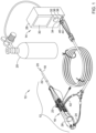
- the control unit 14 which may be separate from the drive assembly 12 (e.g., as shown in FIG. 1 ) or may be included in the drive assembly 12, may include several features.
- the control unit 14 may include a display 30 and a control knob 32 (e.g., a drive mechanism speed (e.g., RPM or other speed) adjustment knob or other control knob).
- a control knob 32 e.g., a drive mechanism speed (e.g., RPM or other speed) adjustment knob or other control knob.
- control unit 14 may include one or more other features for controlling the drive mechanism and/or other features of the drive assembly 12 (e.g., one or more drive mechanism states) including, but not limited to, a processor, memory, input/output devices, a speaker, volume control buttons, on/off power supply switch, drive mechanism activation switch, a timer, a clock, and/or one or more other features.
- the display 30 may be or may include any suitable type of display panel using any suitable display panel technology.
- the display 30 may include one or more of the following types of display panels: Eidophor, Electroluminescent display (ELD), Electronic paper (E Ink, Gyricon), Light emitting diode display (LED), Cathode ray tube (CRT) (Monoscope), Liquid-crystal display (LCD) (TFT, LED, Blue Phase, IPS), Plasma display panel (PDP) (ALiS), Digital Light Processing (DLP), Liquid crystal on silicon (LCoS), Organic light-emitting diode (OLED) (AMOLED), Organic light-emitting transistor (OLET), Surface-conduction electron-emitter display (SED), Field emission display (FED), Laser TV (Quantum dot, Liquid crystal), MEMS display (IMoD, TMOS, DMS), Quantum dot display (QD-LED), Ferro liquid display (FLD), Thick-film dielectric electroluminescent technology (
- the control knob 32 may be any suitable type of control knob. As depicted in FIG. 1 , the control knob 32 may be a physical control knob that is adjusted (e.g., rotated or otherwise translated) to adjust a control feature (e.g., speed of rotation of the drive mechanism or other control feature). Alternatively or in addition, the control knob 32 may be a virtual control knob that may be adjusted by interacting with a touch sensitive surface.
- a control feature e.g., speed of rotation of the drive mechanism or other control feature.
- the control knob 32 may be a virtual control knob that may be adjusted by interacting with a touch sensitive surface.
- the control unit 14 may include one or more ports including, but not limited to, a fiber optic port 34, an electrical port 36, a fluid port 38, and/or one or more other ports.
- the fiber optic port 34 may be configured to receive a fiber optic connector 40 of a fiber optic line 42, where the fiber optic line 42 may be connected to and/or may be part of a position sensor configured to optically sense a position of the drive mechanism. Additionally or alternatively, other types of position sensors may be utilized that have different types of connections to the control unit 14.
- the electrical port 36 may be configured to receive an electrical connector 44 of the electrical line 24, where the electrical line 24 may be connected to and/or may be part of control electronics at the drive assembly 12.
- the electrical line 24 may be directly connected to a main PCB of the drive assembly 12 and may be utilized to power an electrical assembly of the drive assembly 12.
- the fluid port 38 may be configured to receive a fluid line connector 46 of a fluid line 48, where the fluid line 48 may be in communication with the drive mechanism to power the drive mechanism.
- the drive mechanism is an electrical motor or a non-pneumatic drive mechanism
- the fluid port 38, the fluid line connector 46, and/or the fluid line 48 may be omitted, but this is not required.
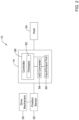
- FIG. 2 depicts a schematic box diagram of the atherectomy system 10 having a drive mechanism 50 and position sensor 52 in communication with the control unit 14 and a host 54 in communication with the control unit 14.
- the host 54 may be one or more of a laptop computer, a desktop computer, tablet computer, a remote server, smartphone, and/or other computing device.
- the host 54 may be in wired and/or wireless communication with the control unit 14, where the wired or wireless communication may include one or more of the communication protocols discussed herein.
- the position sensor 52 may sense a rotational position of the drive mechanism 50 and send an indication of the sensed rotational position of the drive mechanism 50 to the control unit 14 (e.g., send an optical pulse or other indication over the fiber optic line 42 or other line).
- the control unit 14 may then use the indications of the sensed rotational position of the drive mechanism 50 to determine a speed (RPMs) of the drive mechanism 50 and output the determined speed of the drive mechanism 50 to the host 54 for monitoring and/or analysis of the drive mechanism 50.
- RPMs speed
- control unit 14 may sample speed data (e.g., rotational speed, lateral speed, longitudinal speed, etc.) and/or other data at predetermined intervals and send the data to the host 54.
- Example predetermined intervals may include, but are not limited to, 1 millisecond (ms), 2 ms, 5 ms, 10 ms, and/or other suitable intervals.
- the control unit 14 may sample speed data and/or other data upon request from the host 54 and/or other input requesting data.
- the host 54 may be configured to receive data (e.g., operational data that may include, but is not limited to, speed data, on/off data, stall data, data as a function of time, etc.) from the control unit 14. For example, the host 54 may perform analyses on the speed of the drive mechanism 50 and/or other data related to the operation of the drive mechanism 50 and monitor initial overshoot of the drive mechanism (e.g., actual speed versus a setpoint speed upon startup of the drive mechanism), steady state oscillation of the drive mechanism 50, speed changes over run time of the drive mechanism 50, and/or other operations of the drive mechanism 50. In some cases, the host 54 may plot speed versus time on a graph and/or provide other graphical depictions of the received data.
- data e.g., operational data that may include, but is not limited to, speed data, on/off data, stall data, data as a function of time, etc.
- data e.g., operational data that may include, but is not limited to, speed data, on/off data,
- the data transmitted from the control unit 14 to the host 54 may be password protected to establish and/or ensure a high level of data security.
- a password protection protocol may provide one, two, or more levels of data access at the host 54.
- An example password protection protocol providing two levels of data access may include a read mode for data access and a read/write mode for data access.
- Read mode may provide read-only access to the data and may allow a user to view data, but not to interact with the data.
- Read/write mode may provide read-write access to the data and may allow a user to view data and interact with the data (e.g., change the analyses that are run on the data, add notes to the data, change how data is gathered, etc.).
- read mode or access of the password protection protocol may be accessed after entering or providing a primary or base password.
- Read/write mode may be accessed after entering or providing a primary or base password and a secondary password.
- a user's password may automatically give them access to either read mode or read/write mode and only a single password is needed.
- the host 54 may be required by the password protocol to complete an initial handshake with the control unit 14 before receiving access to one or both of the read mode and read/write mode.
- the indication of the sensed rotational position of the drive mechanism 50 may be light pulses and the control unit 14 may include components configured to convert the pulses into analog voltage pulses (e.g., analog indications of rotational positions of the drive mechanism 50).
- the control unit 14 may include a controller 56, an analog-to-digital (A/D) converter 58, and one or more input/output ports 60.
- the A/D converter 58 may convert the analog voltage pulses to a digital voltage signal (e.g., digital indications of the rotational positions of the drive mechanism 50) and firmware 62 of the controller 56 may be configured to sample voltage from the A/D converter 58 at predetermined intervals or upon request from a computing device (e.g., the host 54).
- the indications of speed from the position sensor 52 and/or the output data to the host 54 may pass through the input/output port 60.
- the controller 56 may be or may include a microcontroller. Additionally or alternatively, the controller may include one or more of an application specific integrated circuit (ASIC) and/or an application specific standard product (ASSP). Although not shown, the controller 56 may include a processor and memory, where the processor may be operably coupled to the memory.
- the memory may be used to store any desired information, such as control algorithms, set points, predetermined time intervals for sampling data, schedules, reference schedules, times, diagnostic limits, such as, for example, speed limits, RPM limits, torque limits, and the like.
- the memory may include any of one or more suitable types of storage devices including, but not limited to, RAM, ROM, EPROM, flash memory, a hard drive, and/or the like.
- the memory may include the firmware 62, which may be accessed by the processor.
- the control unit 14 may store information within the memory, and the processor of the controller 56 may subsequently retrieve the stored information from the memory to effect operation of the atherectomy device and/or for analysis (e.g., for analysis by the host 54).
- the processor and/or the memory may include and/or be in communication with a timer.
- FIG. 3 depicts a block diagram of the controller 56 and firmware modules in the firmware 62.
- a position indicator signal 63 for indicating a position of the drive mechanism 50 may be received at the controller 56 and the firmware modules may utilize the position indicator signal 63 to develop control signals 67 for controlling operation (e.g., rotation) of the drive mechanism 50.
- the firmware 62 may include a variety of firmware modules. As shown in FIG. 3 , the firmware 62 may include a speed feedback module 64, a speed compensation module 66, and a damping control module 68. In some cases, the damping control module 68 may include an initial overshoot control 70, a steady state control 72, a stall predictor control 74, and/or one or more other components. In some cases, one or more of the initial overshoot control 70, the steady state control 72, and the stall predictor control 74 may be separate from the damping control module 68. Alternatively or in addition to the control modules and components depicted in FIG. 3 , other firmware modules and/or components may be utilized as desired.
- the modules 64, 66, 68, of the firmware 62 are describe in greater detail below with respect to the methods of FIGs. 4-6 .
- FIG. 4 depicts a method 100 of controlling a speed of the drive mechanism 50.
- an indication of a position of the drive mechanism 50 may be received 102 (e.g., from the A/D converter 58 and/or other component of the control unit 14) and a speed (e.g., RPM or other measurement of speed) of the drive mechanism 50 may be determined 104.
- the speed feedback module 64 may be configured to utilize digital indications (e.g., pulses or other indications) of the position of the drive mechanism 50 outputted from the A/D converter 58 to determine a speed (e.g., in RPMs or other measurement of speed) and provide the determined speed to the speed compensation module 66.
- the firmware 62 may store the output from the A/D converter 58 and the speed feedback module 64 may be configured to sample that stored output from the A/D converter 58 to calculate a speed of the drive mechanism 50.
- the output from the A/D converter 58 may be provided directly to the speed feedback module 64 for calculating the speed of the drive mechanism 50 and/or for other purposes.
- the speed feedback module 64 may sample indications of the drive mechanism position (e.g., stored output from the A/D converter 58, direct output from the A/D converter 58, and/or other indications of the drive mechanism position) and determine a speed of the drive mechanism 50 at predetermined intervals.
- Example predetermined intervals may be ten (10) ms, twenty-five (25) ms, fifty (50) ms, one hundred (100) ms, five hundred (500) ms, second, and/or one or more other suitable intervals.
- the speed feedback module 64 may determine a number of pulses that occurred during the predetermined interval (e.g., the number of pulses since a last time a sample was taken).
- the speed feedback module 64 may enter the indications of the drive mechanism position into an equation that is used to calculate the speed of the drive mechanism 50.
- the indications of the drive mechanism position are pulses
- the indications of the drive mechanism position are sampled every fifty (50) ms, and the speed is determined in RPM
- PulseCounti is the number of indications of a drive mechanism position (e.g., pulses or other indications) received during a predetermined interval, i.
- the speed of the drive mechanism 50 may be determined in one or more other suitable manners, which may be dependent on sampling rate (e.g., the predetermined interval or other interval), type of position measurement of the drive mechanism, and/or one or more other factors.
- the method 100 of FIG. 4 may include receiving 106 a set point for a speed of the drive mechanism 50 (e.g., via the control knob 32 of the control unit 14 or in another suitable manner) and the calculated speed of the drive mechanism 50 may be compared to the received set point to determine 108 a control signal configured to control a speed of the drive mechanism 50.
- the calculated RPM or other measurement of speed may be provided to the speed compensation module 66 for comparison to the received set point speed and determining 108 a control signal 67 based on the comparison.
- the control signal 67 may be a control signal (e.g., a voltage adjustment control signal or other control signal) to a valve that adjusts fluid provided to power the drive mechanism 50.
- control signal 67 may be a control signal that adjusts an amount of current or voltage to the drive mechanism 50. Further, other suitable types of control signals 67 are contemplated that are generally configured to directly or indirectly affect a speed of the drive mechanism 50.
- Speed Control Signal RPM _ Y _ INTERCEPT ⁇ GAIN * RPM
- RPM _ Y _ INTERCEPT SET _ RPM * GAIN
- RPM is the calculated RPM from equation (1)
- GAIN is a configurable gain identified during calibration of the drive mechanism 50
- SET_RPM is an RPM set point as determined by a user of the atherectomy system 10.
- control signal 67 (e.g., Speed Control Signal or other control signal) may be outputted 110 to adjust and/or maintain a speed of the drive mechanism 50.
- the calculated or determined control signal 67 may be outputted to a valve controlling a fluid of fluid to the drive mechanism 50 or directly to a drive mechanism to adjust a voltage or a current to the drive mechanism 50.
- control signal 67 may be modified and/or determined by the damping control module 68 or other module or component of the firmware 62.
- control signal may be modified and/or determined by following the method 200 depicted in FIG. 5 , where the damping control module 68 may be configured to determine a control signal to adjust a speed to of the drive mechanism 50 during an in initial speed (e.g., RPM or other speed) overshoot, at steady state speed (e.g., RPM or other speed) oscillation, and/or at one or more other times during operation of the drive mechanism 50.
- initial speed e.g., RPM or other speed
- steady state speed e.g., RPM or other speed
- the method 200 may include determining 202 an initial control signal for controlling a speed of the drive mechanism 50.
- the initial control signal for controlling the speed of the drive mechanism 50 may be determined 202 according to equation (2), but this is not required.
- the method 200 may further include determining 204 whether a predetermined period of time has elapsed. If the predetermined period of time has not elapsed, the method 200 may include adjusting 206 the initial control signal according to a first mode of operation (e.g., using the initial overshoot control 70, as discussed in greater detail below) to identify a determined control signal (e.g., the determined control signal 67 or other determined control signal).
- a first mode of operation e.g., using the initial overshoot control 70, as discussed in greater detail below
- the determined control signal may be outputted 210 to a further component of the atherectomy system 10 to control a speed of the drive mechanism 50, as discussed herein. If the predetermined period of time has elapsed, the method 200 may include adjusting 208 the initial control signal according to a second mode of operation (e.g., using the steady state control 72, as discussed in greater detail below) to identify the determined controller signal (e.g., the determined control signal 67 or other determined control signal). The determined control signal may be outputted 210 to a further component of the atherectomy system 10 to control a speed of the drive mechanism, as discussed herein.
- a second mode of operation e.g., using the steady state control 72, as discussed in greater detail below
- the determined control signal may be outputted 210 to a further component of the atherectomy system 10 to control a speed of the drive mechanism, as discussed herein.
- the damping control module 68 may include the initial overshoot control 70 configured to calculate a control signal 67 according to an initial equation during a period of time associated with an initial speed overshoot mode of the drive mechanism 50 (e.g., according to the first mode of operation) and the steady state control 72 configured to calculate a control signal 67 according to a different equation for a steady state speed oscillation mode of the drive mechanism 50 (e.g., according to the second mode of operation) after the period of time associated with the initial speed overshoot mode has elapsed.
- the initial overshoot control 70 configured to calculate a control signal 67 according to an initial equation during a period of time associated with an initial speed overshoot mode of the drive mechanism 50 (e.g., according to the first mode of operation)
- the steady state control 72 configured to calculate a control signal 67 according to a different equation for a steady state speed oscillation mode of the drive mechanism 50 (e.g., according to the second mode of operation) after the period of time associated with the initial
- a single, time-dependent equation may be utilized or more than two equations may be utilized to determine the control signals 67 when in the initial speed overshoot mode and the steady state speed oscillation mode.
- the period of time associated with the initial speed overshoot mode may be a suitable period of time upon startup of the drive mechanism 50 prior to the drive mechanism 50 reaching steady state operation relative to startup conditions.
- Example periods of time include, but are not limited to, five hundred (500) ms, one (1) second, two (2) seconds, and/or other periods of time.
- the damping control module 68 may then compare a DAMP_FLOWCAP value from equation (4) to a RPM_Y_INTERCEPT value from equation (3).
- Adjustments 208 to a control signal with steady state control 72 during operation of the drive mechanism 50 in the steady state speed oscillation mode may be based on a rate of change between a current determined speed of the drive mechanism 50 and a previous determined speed of the drive mechanism 50.
- the Current Speed may be the RPM value determined from equation 1 at an interval i
- the Previous Speed may be the RPM value determined from equation 1 at an interval i-n, where n is a number of intervals previous to the current interval, i.
- the Previous Speed may be an average of, or other suitable statistic of, speeds determined using equation (1) for a set of previous intervals.
- a value for Rate of Change may be determined from equation (6) and the (DampFactor) ss may be a fixed value assigned by the firmware 62.
- the firmware 62 of the controller 56 may include a stall predictor control 74.
- the stall predictor control 74 may be in and/or part of the damping control module 68 and/or separate from the damping control module 68.
- the method 300 may include comparing 302 a determined speed (RPM or other measurement of speed) of a drive mechanism 50 at a first time to a determined speed of the drive mechanism 50 at a second time.
- the determined speeds at the first time and the second time may be determined according to equation (1) discussed above.
- speeds of the drive mechanism 50 may be determined in one or more other manners.
- the speed at the predetermined period of time before a current time may be a single speed at the predetermined time before the current time, an average of a plurality of speeds at each of several intervals of periods of time prior to the current time, and/or other statistic related to speeds determined at times prior to the current time.
- the period of time before the current time may be a predetermined period of time.
- Example predetermined periods of time may include fifty (50) ms, one hundred (100) ms, five hundred (500) ms, one (1) second, two (2) seconds, and/or other suitable predetermined period of time greater than and, optionally, a multiple of a period of time between determinations of a speed of the drive mechanism 50.
- the difference (e.g., RPM deviation or RPM deviation trend value) between the speed of the drive mechanism 50 at the current time and the speed of the drive mechanism 50 at a predetermined period of time before the current time may be compared to a threshold value.
- a determination 304 may then be made as to whether the difference between the speed of the drive mechanism 50 at the first time and the speed of the drive mechanism 50 at the second time reaches or goes beyond a threshold.
- the stall predictor control 74 may determine 306 that no stall will occur between a current time and a time at which the next stall prediction is made (e.g., over a future time period equal to or substantially equal to the predetermined period of time).
- the stall predictor control 74 may determine 308 that a stall will occur between a current time and a time at which the next stall prediction is made (e.g., over a future time period equal to or substantially equal to the predetermined period of time).
- the threshold value may be any suitable threshold value.
- the threshold value may be equal to zero (0), may be a number less than zero (0) and/or one or more other suitable values indicative of when a stall may be expected to occur.
- the controller 56 may take one or more action to indicate the determination.
- the one or more actions may be to enable or disable a stall indicator on a display screen (e.g., the display 30), enable or disable a light, enable or disable a sound, enable or disable a control signal for controlling the drive mechanism 50 to address the predicted stall or no-stall, and/or take one or more other actions or inactions.
- the method 300 may include determining 310 when the stall is predicted to occur.
- Example threshold speed levels may include, but are not limited to, may be zero (0) RPM, one hundred (100) RPM, five hundred (500) RPM, one thousand (1,000) RPM, 1,500 RPM, 5,000 RPM, or other suitable threshold value. Additionally or alternatively, the threshold speed value may be a percentage of a set point speed or other motor parameter or state. In some case, the threshold speed value at which a stall may be considered to occur may be greater than zero (0) to facilitate recognizing a stall prior to the stall actually occurring.
- the controller 56 may take one or more actions. For example, the controller 56 may display on the display 30 the predicted time at which a stall may occur, sound an alarm, audibly indicate the predicted time at which a stall may occur, change operation of the drive mechanism in accordance with a control program, send an alert to the host 54, send an alert to a remote device or mobile device, and/or take one or more other actions.
- the methods described herein may include one or more steps other than those steps described herein and/or the described steps may be performed in one or more other orders, as desired unless an expressly indicated otherwise.
- the methods described herein may be repeated during operation of the atherectomy system 10 upon request or initiation, continuously, continuously at predetermined intervals, and/or at other times.
Landscapes
- Health & Medical Sciences (AREA)
- Surgery (AREA)
- Life Sciences & Earth Sciences (AREA)
- Medical Informatics (AREA)
- Animal Behavior & Ethology (AREA)
- Engineering & Computer Science (AREA)
- Biomedical Technology (AREA)
- Heart & Thoracic Surgery (AREA)
- Veterinary Medicine (AREA)
- Molecular Biology (AREA)
- Nuclear Medicine, Radiotherapy & Molecular Imaging (AREA)
- General Health & Medical Sciences (AREA)
- Public Health (AREA)
- Vascular Medicine (AREA)
- Oral & Maxillofacial Surgery (AREA)
- Pathology (AREA)
- Surgical Instruments (AREA)
- External Artificial Organs (AREA)
Applications Claiming Priority (3)
| Application Number | Priority Date | Filing Date | Title |
|---|---|---|---|
| US201862613016P | 2018-01-02 | 2018-01-02 | |
| PCT/US2018/067764 WO2019135976A1 (fr) | 2018-01-02 | 2018-12-27 | Système d'athérectomie |
| EP18834299.2A EP3735190B1 (fr) | 2018-01-02 | 2018-12-27 | Système d'athérectomie |
Related Parent Applications (1)
| Application Number | Title | Priority Date | Filing Date |
|---|---|---|---|
| EP18834299.2A Division EP3735190B1 (fr) | 2018-01-02 | 2018-12-27 | Système d'athérectomie |
Publications (2)
| Publication Number | Publication Date |
|---|---|
| EP4574064A2 true EP4574064A2 (fr) | 2025-06-25 |
| EP4574064A3 EP4574064A3 (fr) | 2025-09-24 |
Family
ID=65024177
Family Applications (2)
| Application Number | Title | Priority Date | Filing Date |
|---|---|---|---|
| EP25153934.2A Pending EP4574064A3 (fr) | 2018-01-02 | 2018-12-27 | Système d'athérectomie |
| EP18834299.2A Active EP3735190B1 (fr) | 2018-01-02 | 2018-12-27 | Système d'athérectomie |
Family Applications After (1)
| Application Number | Title | Priority Date | Filing Date |
|---|---|---|---|
| EP18834299.2A Active EP3735190B1 (fr) | 2018-01-02 | 2018-12-27 | Système d'athérectomie |
Country Status (4)
| Country | Link |
|---|---|
| US (2) | US11172956B2 (fr) |
| EP (2) | EP4574064A3 (fr) |
| JP (1) | JP6987274B2 (fr) |
| WO (1) | WO2019135976A1 (fr) |
Families Citing this family (5)
| Publication number | Priority date | Publication date | Assignee | Title |
|---|---|---|---|---|
| US10826906B2 (en) * | 2018-05-10 | 2020-11-03 | Nidec Motor Corporation | System and computer-implemented method for controlling access to communicative motor |
| CN118697424A (zh) | 2018-11-16 | 2024-09-27 | 美敦力瓦斯科尔勒公司 | 组织去除导管 |
| USD988511S1 (en) | 2019-11-15 | 2023-06-06 | Medtronic Vascular, Inc | Catheter handle |
| US11696793B2 (en) | 2021-03-19 | 2023-07-11 | Crossfire Medical Inc | Vascular ablation |
| JP2023128737A (ja) * | 2022-03-04 | 2023-09-14 | テルモ株式会社 | 医療システムの制御装置、医療システムおよび医療システムの制御方法 |
Family Cites Families (13)
| Publication number | Priority date | Publication date | Assignee | Title |
|---|---|---|---|---|
| US3623474A (en) * | 1966-07-25 | 1971-11-30 | Medrad Inc | Angiographic injection equipment |
| US5135483A (en) * | 1991-07-22 | 1992-08-04 | Dow Corning Wright Corporation | Atherectomy device with a removable drive system |
| US6039747A (en) | 1998-04-08 | 2000-03-21 | Shturman Cardiology Systems, Inc. | Rotational atherectomy device with improved optical tachometer |
| US7174240B2 (en) | 2001-10-19 | 2007-02-06 | Cardiovascular Systems, Inc. | Control system for rotational angioplasty device |
| US8303304B2 (en) * | 2006-12-18 | 2012-11-06 | Dentsply International, Inc. | Closed loop speed control for a pneumatic dental handpiece |
| US8657821B2 (en) | 2008-11-14 | 2014-02-25 | Revascular Therapeutics Inc. | Method and system for reversibly controlled drilling of luminal occlusions |
| WO2013129989A1 (fr) * | 2012-02-27 | 2013-09-06 | Aktiebolaget Skf | Surveillance d'état d'un système de rotation sur la base d'un signal horodaté |
| EP3037053A4 (fr) * | 2013-08-21 | 2017-06-07 | Olympus Corporation | Outil et système de traitement |
| US10702300B2 (en) * | 2014-07-18 | 2020-07-07 | Cardiovascular Systems, Inc. | Methods, devices and systems for slow rotation of drive shaft driven atherectomy systems |
| US10405878B2 (en) * | 2014-07-25 | 2019-09-10 | Boston Scientific Scimed, Inc. | Rotatable medical device |
| US9167418B1 (en) * | 2015-06-22 | 2015-10-20 | Invictus Technology Group, Inc. | Method and apparatus for controlling input to a mobile computing device located inside a vehicle |
| US10226276B2 (en) * | 2015-06-26 | 2019-03-12 | Covidien Lp | Tissue-removing catheter including operational control mechanism |
| EP3723634B1 (fr) * | 2017-12-12 | 2024-02-28 | Boston Scientific Scimed, Inc. | Dispositif médical rotatif |
-
2018
- 2018-12-27 US US16/234,501 patent/US11172956B2/en active Active
- 2018-12-27 EP EP25153934.2A patent/EP4574064A3/fr active Pending
- 2018-12-27 JP JP2020555733A patent/JP6987274B2/ja active Active
- 2018-12-27 EP EP18834299.2A patent/EP3735190B1/fr active Active
- 2018-12-27 WO PCT/US2018/067764 patent/WO2019135976A1/fr not_active Ceased
-
2021
- 2021-11-12 US US17/524,782 patent/US11744610B2/en active Active
Also Published As
| Publication number | Publication date |
|---|---|
| US20220061879A1 (en) | 2022-03-03 |
| WO2019135976A1 (fr) | 2019-07-11 |
| JP6987274B2 (ja) | 2021-12-22 |
| EP4574064A3 (fr) | 2025-09-24 |
| EP3735190B1 (fr) | 2025-01-29 |
| JP2021509079A (ja) | 2021-03-18 |
| US20190201051A1 (en) | 2019-07-04 |
| US11172956B2 (en) | 2021-11-16 |
| US11744610B2 (en) | 2023-09-05 |
| EP3735190A1 (fr) | 2020-11-11 |
Similar Documents
| Publication | Publication Date | Title |
|---|---|---|
| US11744610B2 (en) | Atherectomy system | |
| US11819238B2 (en) | Rotational medical device | |
| US11696782B2 (en) | Rotational medical device | |
| AU2008242981B2 (en) | Powered surgical system | |
| US11986206B2 (en) | Atherectomy system | |
| US20140371770A1 (en) | Controller for an atherectomy device | |
| US11471061B2 (en) | Apparatus and method for intravascular measurements | |
| KR20200028386A (ko) | 혈액 펌프 지원의 조절을 위한 심장 매개변수의 결정 | |
| WO2007109422A3 (fr) | Systeme de commande pour le franchissement d'occlusions vasculaires | |
| US10172662B2 (en) | Surgical screwdriver | |
| JP6109470B2 (ja) | カテーテルのもつれの指示 | |
| JP6603715B2 (ja) | モニタリングシステム及びガイドワイヤ | |
| EP4400070B1 (fr) | Systèmes d'utilisation de l'état d'un moteur pendant une procédure de forage chirurgical pour améliorer l'efficacité d'un algorithme de percée | |
| US12369943B2 (en) | Atherectomy system current sensing, processing and display | |
| US20220022878A1 (en) | Systems and methods for controlling a surgical stapling instrument | |
| US20240148958A1 (en) | Aspiration systems, devices and methods for treating ischemic stroke | |
| KR102537304B1 (ko) | 음파 탐지를 이용한 캐뉼라 기반의 지방흡입 장치 및 위험도 모니터링 방법 | |
| CN114585322A (zh) | 用于检测手术器械与患者组织的物理接触的系统和方法 | |
| CN114980833A (zh) | 基于插入力的控制和反馈 |
Legal Events
| Date | Code | Title | Description |
|---|---|---|---|
| PUAI | Public reference made under article 153(3) epc to a published international application that has entered the european phase |
Free format text: ORIGINAL CODE: 0009012 |
|
| STAA | Information on the status of an ep patent application or granted ep patent |
Free format text: STATUS: REQUEST FOR EXAMINATION WAS MADE |
|
| 17P | Request for examination filed |
Effective date: 20250224 |
|
| AC | Divisional application: reference to earlier application |
Ref document number: 3735190 Country of ref document: EP Kind code of ref document: P |
|
| AK | Designated contracting states |
Kind code of ref document: A2 Designated state(s): AL AT BE BG CH CY CZ DE DK EE ES FI FR GB GR HR HU IE IS IT LI LT LU LV MC MK MT NL NO PL PT RO RS SE SI SK SM TR |
|
| PUAL | Search report despatched |
Free format text: ORIGINAL CODE: 0009013 |
|
| AK | Designated contracting states |
Kind code of ref document: A3 Designated state(s): AL AT BE BG CH CY CZ DE DK EE ES FI FR GB GR HR HU IE IS IT LI LT LU LV MC MK MT NL NO PL PT RO RS SE SI SK SM TR |
|
| RIC1 | Information provided on ipc code assigned before grant |
Ipc: A61B 17/3207 20060101AFI20250821BHEP |