EP4574100A1 - Expandierbarer stent mit programmierbarer form und/oder programmierbaren mechanischen eigenschaften - Google Patents
Expandierbarer stent mit programmierbarer form und/oder programmierbaren mechanischen eigenschaften Download PDFInfo
- Publication number
- EP4574100A1 EP4574100A1 EP23307330.3A EP23307330A EP4574100A1 EP 4574100 A1 EP4574100 A1 EP 4574100A1 EP 23307330 A EP23307330 A EP 23307330A EP 4574100 A1 EP4574100 A1 EP 4574100A1
- Authority
- EP
- European Patent Office
- Prior art keywords
- stent
- cell
- cells
- beams
- shape
- Prior art date
- Legal status (The legal status is an assumption and is not a legal conclusion. Google has not performed a legal analysis and makes no representation as to the accuracy of the status listed.)
- Pending
Links
Images


Classifications
-
- A—HUMAN NECESSITIES
- A61—MEDICAL OR VETERINARY SCIENCE; HYGIENE
- A61F—FILTERS IMPLANTABLE INTO BLOOD VESSELS; PROSTHESES; DEVICES PROVIDING PATENCY TO, OR PREVENTING COLLAPSING OF, TUBULAR STRUCTURES OF THE BODY, e.g. STENTS; ORTHOPAEDIC, NURSING OR CONTRACEPTIVE DEVICES; FOMENTATION; TREATMENT OR PROTECTION OF EYES OR EARS; BANDAGES, DRESSINGS OR ABSORBENT PADS; FIRST-AID KITS
- A61F2/00—Filters implantable into blood vessels; Prostheses, i.e. artificial substitutes or replacements for parts of the body; Appliances for connecting them with the body; Devices providing patency to, or preventing collapsing of, tubular structures of the body, e.g. stents
- A61F2/82—Devices providing patency to, or preventing collapsing of, tubular structures of the body, e.g. stents
- A61F2/86—Stents in a form characterised by the wire-like elements; Stents in the form characterised by a net-like or mesh-like structure
- A61F2/90—Stents in a form characterised by the wire-like elements; Stents in the form characterised by a net-like or mesh-like structure characterised by a net-like or mesh-like structure
- A61F2/91—Stents in a form characterised by the wire-like elements; Stents in the form characterised by a net-like or mesh-like structure characterised by a net-like or mesh-like structure made from perforated sheets or tubes, e.g. perforated by laser cuts or etched holes
- A61F2/915—Stents in a form characterised by the wire-like elements; Stents in the form characterised by a net-like or mesh-like structure characterised by a net-like or mesh-like structure made from perforated sheets or tubes, e.g. perforated by laser cuts or etched holes with bands having a meander structure, adjacent bands being connected to each other
- A61F2002/91508—Stents in a form characterised by the wire-like elements; Stents in the form characterised by a net-like or mesh-like structure characterised by a net-like or mesh-like structure made from perforated sheets or tubes, e.g. perforated by laser cuts or etched holes with bands having a meander structure, adjacent bands being connected to each other the meander having a difference in amplitude along the band
-
- A—HUMAN NECESSITIES
- A61—MEDICAL OR VETERINARY SCIENCE; HYGIENE
- A61F—FILTERS IMPLANTABLE INTO BLOOD VESSELS; PROSTHESES; DEVICES PROVIDING PATENCY TO, OR PREVENTING COLLAPSING OF, TUBULAR STRUCTURES OF THE BODY, e.g. STENTS; ORTHOPAEDIC, NURSING OR CONTRACEPTIVE DEVICES; FOMENTATION; TREATMENT OR PROTECTION OF EYES OR EARS; BANDAGES, DRESSINGS OR ABSORBENT PADS; FIRST-AID KITS
- A61F2/00—Filters implantable into blood vessels; Prostheses, i.e. artificial substitutes or replacements for parts of the body; Appliances for connecting them with the body; Devices providing patency to, or preventing collapsing of, tubular structures of the body, e.g. stents
- A61F2/82—Devices providing patency to, or preventing collapsing of, tubular structures of the body, e.g. stents
- A61F2/86—Stents in a form characterised by the wire-like elements; Stents in the form characterised by a net-like or mesh-like structure
- A61F2/90—Stents in a form characterised by the wire-like elements; Stents in the form characterised by a net-like or mesh-like structure characterised by a net-like or mesh-like structure
- A61F2/91—Stents in a form characterised by the wire-like elements; Stents in the form characterised by a net-like or mesh-like structure characterised by a net-like or mesh-like structure made from perforated sheets or tubes, e.g. perforated by laser cuts or etched holes
- A61F2/915—Stents in a form characterised by the wire-like elements; Stents in the form characterised by a net-like or mesh-like structure characterised by a net-like or mesh-like structure made from perforated sheets or tubes, e.g. perforated by laser cuts or etched holes with bands having a meander structure, adjacent bands being connected to each other
- A61F2002/9155—Adjacent bands being connected to each other
- A61F2002/91558—Adjacent bands being connected to each other connected peak to peak
-
- A—HUMAN NECESSITIES
- A61—MEDICAL OR VETERINARY SCIENCE; HYGIENE
- A61F—FILTERS IMPLANTABLE INTO BLOOD VESSELS; PROSTHESES; DEVICES PROVIDING PATENCY TO, OR PREVENTING COLLAPSING OF, TUBULAR STRUCTURES OF THE BODY, e.g. STENTS; ORTHOPAEDIC, NURSING OR CONTRACEPTIVE DEVICES; FOMENTATION; TREATMENT OR PROTECTION OF EYES OR EARS; BANDAGES, DRESSINGS OR ABSORBENT PADS; FIRST-AID KITS
- A61F2230/00—Geometry of prostheses classified in groups A61F2/00 - A61F2/26 or A61F2/82 or A61F9/00 or A61F11/00 or subgroups thereof
- A61F2230/0002—Two-dimensional shapes, e.g. cross-sections
- A61F2230/0004—Rounded shapes, e.g. with rounded corners
- A61F2230/001—Figure-8-shaped, e.g. hourglass-shaped
-
- A—HUMAN NECESSITIES
- A61—MEDICAL OR VETERINARY SCIENCE; HYGIENE
- A61F—FILTERS IMPLANTABLE INTO BLOOD VESSELS; PROSTHESES; DEVICES PROVIDING PATENCY TO, OR PREVENTING COLLAPSING OF, TUBULAR STRUCTURES OF THE BODY, e.g. STENTS; ORTHOPAEDIC, NURSING OR CONTRACEPTIVE DEVICES; FOMENTATION; TREATMENT OR PROTECTION OF EYES OR EARS; BANDAGES, DRESSINGS OR ABSORBENT PADS; FIRST-AID KITS
- A61F2250/00—Special features of prostheses classified in groups A61F2/00 - A61F2/26 or A61F2/82 or A61F9/00 or A61F11/00 or subgroups thereof
- A61F2250/0014—Special features of prostheses classified in groups A61F2/00 - A61F2/26 or A61F2/82 or A61F9/00 or A61F11/00 or subgroups thereof having different values of a given property or geometrical feature, e.g. mechanical property or material property, at different locations within the same prosthesis
- A61F2250/0039—Special features of prostheses classified in groups A61F2/00 - A61F2/26 or A61F2/82 or A61F9/00 or A61F11/00 or subgroups thereof having different values of a given property or geometrical feature, e.g. mechanical property or material property, at different locations within the same prosthesis differing in diameter
Definitions
- the invention relates to an expandable stent, in particular a balloon expandable stent.
- a stent is prosthetic device, tube-shaped, which is used for implantation in a body passageway (e.g. a lumen of a vein or of an artery) to keep the passageway open.
- a body passageway e.g. a lumen of a vein or of an artery
- Known expandable stents are configured to pass from an initial contracted configuration, in which the stent has a certain diameter, to an expanded configuration, in which said diameter increases.
- the expanded stents are usually tubular or cylindrical, meaning that their diameter is constant over the entire length of the stent.
- Figure 1 represents a balloon expandable stent of prior art in the contracted configuration and the expanded configuration.
- EP 1 790 314 discloses an expandable stent comprising a body with a wall having intersecting members (or web structure).
- the intersecting members are arranged to define a plurality of repeating patterns.
- the flexibility and rigidity of the stent is varied along the length by varying the repeating pattern design, making it possible for the stent to curve.
- the stent curves only by being forced into a curve by the blood vessel in which it is inserted. Therefore the stent is disrupting the nominal form of the blood vessel in a non-controlled way.
- the present invention aims at proposing an expandable stent which is able to deploy or expand in a non rectilinear manner (curved or flared) and which enables a variation of the radial force applied by the stent to the tissue to reduce springback in the area to be treated and preserve the surrounding healthy areas.
- the invention provides a stent comprising a body with a wall having a web structure configured to expand from a contracted configuration to an expanded configuration, the web structure comprising a plurality of cells, the geometry and dimensions of each cell being configured to obtain a target shape and/or target mechanical properties of the stent when the stent passes from the contracted configuration to the expanded configuration upon the application of a predefined radially outward displacement on the stent.
- the stent according to the present invention makes it possible to predict and control the shape of the stent once deployed/expanded, as well as the mechanical properties of the stent.
- the prediction of the shape and the mechanical properties is made locally (i.e. for each cell), making it possible to predict very accurately the shape and the mechanical properties of the entire stent.
- the stent invention enhances the quality of care for patients suffering from congenital heart diseases which are currently untreated. It is for example possible to:
- the web structure comprises multiple parallel chains of cells bound together.
- each cell is configured to present a target Poisson's ratio when the stent passes from the contracted configuration to the expanded configuration.
- each cell is configured to present a unique target Poisson's ratio when the stent passes from the contracted configuration to the expanded configuration.
- each beam of each cell has dimensions which are predefined so as to obtain the target shape and/or the target mechanical properties.
- the length and the width of each beam of each cell are predefined so as to obtain the target shape and/or the target mechanical properties.
- the geometry of all the cells is identical, at least one cell having different dimensions from that of another cell.
- all the cells have the same overall length and overall width.
- each cell comprises four beams and two hinges, the beams and the hinges forming a diamond shape in the contracted configuration.
- the stent is made of an elastoplastic material.
- the stent is made of stainless steel.
- Figure 2 shows an expandable stent 1 according to one embodiment of the invention, along with a balloon 2. Balloon 2 is inserted into stent 1.
- Figure 3 shows a numerical model of stent 1 in the contracted configuration at a), and in the expanded configuration at b).
- the diamond cell of figure 4a is asymmetrical.
- Upper beams 120a have different lengths.
- One short upper beam 120a has a length L1 and one long upper beam 120a has a length L2 different of L1.
- Lower beams 120b have different lengths.
- One short lower beam 120b has a length L1 and one long lower beam 120b has a length L2 different of L1.
- cell 12 can be a diamond symmetrical cell. All four beams 120a, 120b can have the same length.
- Cell 12 has an overall length L O corresponding in the embodiment of figure 4a to the distance between the hinges 121 or the sum of lengths L1 and L2.
- Cell 12 has an overall width W O corresponding in the embodiment of figure 4a to the distance between the upper beams 120a and the lower beams 120b.
- Cell 12 of figure 4b comprises beams 120a, 120b, 120c, hinges 121 and cross arms 122.
- cell 12 comprises twelve beams 120a, 120b, 120c (two upper beams 120a, two lower beams 120b and eight intermediate beams 120c), eight hinges 121 and two cross arms 122.
- the number of beams, hinges and cross arms can be different.
- Hinges 121 are here C-shaped arms or reverse C-shaped arms.
- cell 12 comprises four C-shaped arms and four reverse C-shaped arms.
- Each hinge 121 links a pair of beams 120a, 120b, 120c. Every two hinges 121 and three beams 120a, 120b, 120c form together an S-shape or a reverse S-shape when the stent (and thus each cell) is in the contracted configuration.
- Cell 12 comprises two S-shapes and two reverse S-shapes.
- Each S-shape is here formed by three beams 120a, 120b, 120c and two hinges 121 (one C-shaped arm and one reverse C-shaped arm).
- Each reverse S-shape is here formed by three beams 120a, 120b, 120c and two hinges 121 (one C-shaped arm and one reverse C-shaped arm).
- Each cross arm 122 links one of the S-shapes to one of the reverse S-shapes.
- Cross arm 122 is substantially perpendicular to the beams 120a, 120b, 120c when the stent (and thus each cell) is in the contracted configuration.
- Cell 12 is here symmetrical about a longitudinal median axis, but can be of course asymmetrical.
- Cell 12 has an overall length L O corresponding in the embodiment of figure 4b to the distance between the cross arms 122.
- Cell 12 has an overall width W O corresponding in the embodiment of figure 4b to the distance between the upper beams 120a and the lower beams 120b.
- the geometry and dimensions of the cells, and the radially outward displacement applied on the inner face of the stent has an impact on the shape and the properties of the stent in the expanded configuration.
- the invention makes it possible, by tuning the local properties of each cell, to obtain the target shape and/or properties of the stent in the expanded configuration.
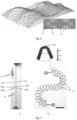
- figure 5 shows the parameters which enable the variation of the mechanical properties and the shape of cells 12.
- This figure presents results for the open lattice cell 12 of figure 4b provided as a non-limiting example. The same reasoning applies to other shapes of cells.
- the length L beam of the beams and the width W beam of the beams are varied.
- the width W beam of the beams shall mean the dimension of the beams in a transverse direction (here the longitudinal direction of the stent).
- the width of all the beams is varied equally in this example. The higher the width, the thicker it is represented on the figure.
- Figure 5b shows, on the one hand, the stress-strain response of some of the cells of figure 5a as a function of the effective strain.
- figure 5b shows the stress-strain response of twelve cells m0, m2, m4, m5, m7, m9, m10, m12, m14, m15, m17, m19 having all the same shape but different length L beam and/or width W beam of the beams.
- the stress-strain response varies when varying the length L beam and the width W beam of the beams. The higher the length L beam of the beams, the lower the stress-strain response. The higher the width W beam of the beams, the higher the stress-strain response.
- figure 5c shows Poisson's ratio for some of the cells of figure 5a as a function of the effective strain.
- figure 5b shows Poisson's ratio of cells m0, m2, m4, m5, m7, m9, m10, m12, m14, m15, m17, m19 having all the same shape but different length L beam and/or width W beam of the beams.
- the method of the invention in order to obtain a target shape and/or target mechanical properties of stent 1 comprises the following steps:
- the mapping step is made possible thanks to the knowledge of the mechanical properties of the material used to manufacture the stent.
- the mechanical properties are known through analytical models, as detailed below.
- Each cell is designed so as to achieve the local target shape and/or target mechanical properties.
- the mapping step is carried out taking into account the displacement applied on the stent by balloon 2.
- balloon 2 When balloon 2 is inflated, all cells 12 are subject to the same load, which is the opening by balloon 2. Balloon 2 has the same size throughout. The process to find the geometry and dimensions of each cell 12 is detailed below.
- stent 1 is manufactured according to the set arrangements of cells.
- Stent 1 can be produced by laser cutting.
- the stent is meshed such that all cells 12 have the same overall dimensions, namely the same overall length L O and the same overall width W O . All cells 12 can have the same shape.
- the dimensions of beams 120a, 120b, 120c (in particular the length and/or the width of the beams) for each cell 12 are varied locally. Said otherwise, the dimensions of beams 120a, 120b, 120c are varied while maintaining constant the overall dimensions of cells 12.
- balloon 2 is inflated, all cells 12 are subject to the same load, which is the opening by the balloon.
- different deformations are obtained in terms of extension for the same applied load. It is thus possible to predict the variation of the length along the stent, as well as the stent's diameter and curvature's variations.
- all cells 12 have the same shape, namely the shape represented at figure 4b .
- the meshing of the stent is represented in the lower part of the figure.
- All the cells have the same overall dimensions (i.e. the same overall length L O and the same overall width W O ).
- Two types of cells 12 are used, namely a first type C1 and a second type C2.
- the length of the beams of first type C1 of cells is higher than the length of the beams of second type C2 of cells.
- the overall dimensions of both types C1, C2 are the same, as said before.
- the specific shape of cells 12 used allows varying the opening and recovery (or springback) distance of each cell in the longitudinal direction, and the way the cells retract in the transverse direction.
- the cells do not deform in the same way in both longitudinal and transverse directions once the applied load/force is released.
- the deformed cells are represented on the figure, showing positive bumps and negative bumps created thanks to the shape of the cells and the specific meshing. Of course, other shapes of cells can result in the same effect.
- simulation software To validate the method of the invention for finding the target shape and/or target mechanical properties, analytical models are injected into a simulation software. Numerical models are generated by the simulation software.
- the simulation software is typically a finite element software.
- the simulation software enables the prediction of the behavior of an element (typically the stent) under the effect of a load.
- the simulation software can be for example ABAQUS, ANSYS, SimScale or any other known simulation software using finite element method.
- experimental tension tests for assemblies with parallel chains of cells Comparison is made between the experimental tension tests, the analytical models and the numerical models in order to validate the method. This process is explained and illustrated with examples hereafter.
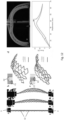
- Figure 7 shows an example of a chain of cells 12.
- the chain of cells is typically 3D printed for the experimental test.
- the chain of cells comprises diamond cells (as in the example of figure 4a ).
- Each cell 12 comprises four beams 120a, 120b connected by hinges 121.
- Cells 12 are here asymmetrical. Upper beams 120a have different lengths from one another and lower beams 120b have different lengths from one another.
- the stretching causes plastic deformation of the structure.
- the chain of cells adopts a curved shape at equilibrium.
- the curvature of the shape at equilibrium is programmed from the asymmetry of cells 12 along the chain to form two semicircles of opposite curvature.
- PETG polyethylene terephthalate glycol-modified
- the beams act as lever arms that concentrate bending moment in the hinges.
- the hinge of the shorter beam stores more plastic deformation, which results in a larger equilibrium angle ⁇ 1 .
- This asymmetry has two origins: (i) basic geometry enforces that the opening angle of the shorter beams is larger than that of the longer ones; and (ii) the long beams bend more than the short ones, thereby amplifying this disparity.
- the deformation in the hinges is plastic, so that equilibrium angles ⁇ 1 and ⁇ 2 differ when the boundaries are released, breaking the system's symmetry and causing the cell to tilt with angle ⁇ and length ⁇ eq .
- Stacking cells together thus allows to locally control the discrete curvature ⁇ ⁇ ⁇ / ⁇ eq and thus obtain arbitrarily complex shapes in the plane.
Landscapes
- Health & Medical Sciences (AREA)
- Engineering & Computer Science (AREA)
- Biomedical Technology (AREA)
- Heart & Thoracic Surgery (AREA)
- Optics & Photonics (AREA)
- Cardiology (AREA)
- Oral & Maxillofacial Surgery (AREA)
- Transplantation (AREA)
- Physics & Mathematics (AREA)
- Vascular Medicine (AREA)
- Life Sciences & Earth Sciences (AREA)
- Animal Behavior & Ethology (AREA)
- General Health & Medical Sciences (AREA)
- Public Health (AREA)
- Veterinary Medicine (AREA)
- Prostheses (AREA)
Priority Applications (2)
| Application Number | Priority Date | Filing Date | Title |
|---|---|---|---|
| EP23307330.3A EP4574100A1 (de) | 2023-12-21 | 2023-12-21 | Expandierbarer stent mit programmierbarer form und/oder programmierbaren mechanischen eigenschaften |
| PCT/EP2024/088260 WO2025133358A1 (en) | 2023-12-21 | 2024-12-20 | Method for obtaining an expandable stent with a target shape and/or target mechanical properties |
Applications Claiming Priority (1)
| Application Number | Priority Date | Filing Date | Title |
|---|---|---|---|
| EP23307330.3A EP4574100A1 (de) | 2023-12-21 | 2023-12-21 | Expandierbarer stent mit programmierbarer form und/oder programmierbaren mechanischen eigenschaften |
Publications (1)
| Publication Number | Publication Date |
|---|---|
| EP4574100A1 true EP4574100A1 (de) | 2025-06-25 |
Family
ID=89620165
Family Applications (1)
| Application Number | Title | Priority Date | Filing Date |
|---|---|---|---|
| EP23307330.3A Pending EP4574100A1 (de) | 2023-12-21 | 2023-12-21 | Expandierbarer stent mit programmierbarer form und/oder programmierbaren mechanischen eigenschaften |
Country Status (2)
| Country | Link |
|---|---|
| EP (1) | EP4574100A1 (de) |
| WO (1) | WO2025133358A1 (de) |
Citations (4)
| Publication number | Priority date | Publication date | Assignee | Title |
|---|---|---|---|---|
| EP1790314A2 (de) | 1996-03-05 | 2007-05-30 | Evysio Medical Devices Ulc | Expandierbarer Stent |
| US20160235895A1 (en) * | 2011-10-25 | 2016-08-18 | Cook Medical Technologies Llc | Coated stent |
| US20190015231A1 (en) * | 2015-10-27 | 2019-01-17 | Contego Medical, Llc | Stents for use with transluminal angioplasty devices |
| WO2019033121A1 (en) * | 2017-08-11 | 2019-02-14 | Elixir Medical Corporation | Uncaging stent |
-
2023
- 2023-12-21 EP EP23307330.3A patent/EP4574100A1/de active Pending
-
2024
- 2024-12-20 WO PCT/EP2024/088260 patent/WO2025133358A1/en active Pending
Patent Citations (4)
| Publication number | Priority date | Publication date | Assignee | Title |
|---|---|---|---|---|
| EP1790314A2 (de) | 1996-03-05 | 2007-05-30 | Evysio Medical Devices Ulc | Expandierbarer Stent |
| US20160235895A1 (en) * | 2011-10-25 | 2016-08-18 | Cook Medical Technologies Llc | Coated stent |
| US20190015231A1 (en) * | 2015-10-27 | 2019-01-17 | Contego Medical, Llc | Stents for use with transluminal angioplasty devices |
| WO2019033121A1 (en) * | 2017-08-11 | 2019-02-14 | Elixir Medical Corporation | Uncaging stent |
Also Published As
| Publication number | Publication date |
|---|---|
| WO2025133358A1 (en) | 2025-06-26 |
Similar Documents
| Publication | Publication Date | Title |
|---|---|---|
| US6527799B2 (en) | Expandable medical device with ductile hinges | |
| AU773731B2 (en) | Expandable medical device with ductile hinges | |
| DE60031490T2 (de) | Stents für Angioplastie | |
| EP1723930B1 (de) | Biegsame medizinische Vorrichtung | |
| US20130331931A1 (en) | Apparatus for Replacing a Native Heart Valve and Method of Making the Same | |
| EP1559382B1 (de) | Dehnbarer, nicht knickender, gewickelter Stent | |
| KR102197010B1 (ko) | 스텐트 | |
| KR102195532B1 (ko) | 스텐트 | |
| US20070173927A1 (en) | Self-expandable shape memory alloy stent and method for fabricating the same | |
| JP6488282B2 (ja) | 形状変化構体 | |
| EP4574100A1 (de) | Expandierbarer stent mit programmierbarer form und/oder programmierbaren mechanischen eigenschaften | |
| EP4346707A1 (de) | Selbstexpandierender stent mit gestuftem radialkraftprofil | |
| KR102453480B1 (ko) | 혈전 제거용 스텐트 | |
| US10722390B2 (en) | Stent made of polymer material having ratchet | |
| EP2881089A1 (de) | Stent zur Implantation in Blutgefäße | |
| WO2021002766A1 (en) | A balloon-expandable heart valve frame and a method for manufacturing the balloon-expandable heart valve frame | |
| Montgomery Liljeroth | Auxetic Structures in Cardiovascular Stent Design | |
| CA2793650A1 (en) | Stent devices made of a lattice with smooth shape cells improving stent fatigue life |
Legal Events
| Date | Code | Title | Description |
|---|---|---|---|
| PUAI | Public reference made under article 153(3) epc to a published international application that has entered the european phase |
Free format text: ORIGINAL CODE: 0009012 |
|
| STAA | Information on the status of an ep patent application or granted ep patent |
Free format text: STATUS: THE APPLICATION HAS BEEN PUBLISHED |
|
| AK | Designated contracting states |
Kind code of ref document: A1 Designated state(s): AL AT BE BG CH CY CZ DE DK EE ES FI FR GB GR HR HU IE IS IT LI LT LU LV MC ME MK MT NL NO PL PT RO RS SE SI SK SM TR |
|
| STAA | Information on the status of an ep patent application or granted ep patent |
Free format text: STATUS: THE APPLICATION IS DEEMED TO BE WITHDRAWN |