EP4574103A1 - Orthèse de cheville - Google Patents
Orthèse de cheville Download PDFInfo
- Publication number
- EP4574103A1 EP4574103A1 EP23020557.7A EP23020557A EP4574103A1 EP 4574103 A1 EP4574103 A1 EP 4574103A1 EP 23020557 A EP23020557 A EP 23020557A EP 4574103 A1 EP4574103 A1 EP 4574103A1
- Authority
- EP
- European Patent Office
- Prior art keywords
- base body
- ankle
- strap
- wearer
- orthosis
- Prior art date
- Legal status (The legal status is an assumption and is not a legal conclusion. Google has not performed a legal analysis and makes no representation as to the accuracy of the status listed.)
- Granted
Links
Images


Classifications
-
- A—HUMAN NECESSITIES
- A61—MEDICAL OR VETERINARY SCIENCE; HYGIENE
- A61F—FILTERS IMPLANTABLE INTO BLOOD VESSELS; PROSTHESES; DEVICES PROVIDING PATENCY TO, OR PREVENTING COLLAPSING OF, TUBULAR STRUCTURES OF THE BODY, e.g. STENTS; ORTHOPAEDIC, NURSING OR CONTRACEPTIVE DEVICES; FOMENTATION; TREATMENT OR PROTECTION OF EYES OR EARS; BANDAGES, DRESSINGS OR ABSORBENT PADS; FIRST-AID KITS
- A61F5/00—Orthopaedic methods or devices for non-surgical treatment of bones or joints; Nursing devices ; Anti-rape devices
- A61F5/01—Orthopaedic devices, e.g. long-term immobilising or pressure directing devices for treating broken or deformed bones such as splints, casts or braces
- A61F5/0102—Orthopaedic devices, e.g. long-term immobilising or pressure directing devices for treating broken or deformed bones such as splints, casts or braces specially adapted for correcting deformities of the limbs or for supporting them; Ortheses, e.g. with articulations
- A61F5/0104—Orthopaedic devices, e.g. long-term immobilising or pressure directing devices for treating broken or deformed bones such as splints, casts or braces specially adapted for correcting deformities of the limbs or for supporting them; Ortheses, e.g. with articulations without articulation
- A61F5/0111—Orthopaedic devices, e.g. long-term immobilising or pressure directing devices for treating broken or deformed bones such as splints, casts or braces specially adapted for correcting deformities of the limbs or for supporting them; Ortheses, e.g. with articulations without articulation for the feet or ankles
-
- A—HUMAN NECESSITIES
- A61—MEDICAL OR VETERINARY SCIENCE; HYGIENE
- A61F—FILTERS IMPLANTABLE INTO BLOOD VESSELS; PROSTHESES; DEVICES PROVIDING PATENCY TO, OR PREVENTING COLLAPSING OF, TUBULAR STRUCTURES OF THE BODY, e.g. STENTS; ORTHOPAEDIC, NURSING OR CONTRACEPTIVE DEVICES; FOMENTATION; TREATMENT OR PROTECTION OF EYES OR EARS; BANDAGES, DRESSINGS OR ABSORBENT PADS; FIRST-AID KITS
- A61F5/00—Orthopaedic methods or devices for non-surgical treatment of bones or joints; Nursing devices ; Anti-rape devices
- A61F5/01—Orthopaedic devices, e.g. long-term immobilising or pressure directing devices for treating broken or deformed bones such as splints, casts or braces
- A61F5/0102—Orthopaedic devices, e.g. long-term immobilising or pressure directing devices for treating broken or deformed bones such as splints, casts or braces specially adapted for correcting deformities of the limbs or for supporting them; Ortheses, e.g. with articulations
- A61F5/0127—Orthopaedic devices, e.g. long-term immobilising or pressure directing devices for treating broken or deformed bones such as splints, casts or braces specially adapted for correcting deformities of the limbs or for supporting them; Ortheses, e.g. with articulations for the feet
Definitions
- the present invention relates to an ankle orthosis according to the preamble of claim 1.
- Such ankle orthoses are used to support, relieve, and immobilize the wearer's foot, particularly in cases of sprains, ankle fractures, pain in tendons and ligaments in the ankle area, or after surgery.
- the orthosis prevents the wearer from bending the foot, especially the ankle, sideways and/or upward or downward.
- Such orthoses also serve to reduce swelling, particularly edema and hematomas.
- ankle orthoses typically consist of a textile, preferably compressive, base body, particularly to promote the reduction of swelling, the shape of which is adapted to the anatomy of the foot in the ankle joint area. When worn, this base body surrounds the ankle joint and the adjacent areas of the foot, preferably on all sides.
- ankle orthoses are also known to have, in addition to the textile base body, a stabilizing element, which is preferably connected to the base body. The stabilizing element prevents lateral bending and/or flexion of the foot.
- a strap system which is preferably attached to the base body or the stabilizing element, the base body and the stabilizing element are firmly applied to the ankle joint and fixed there.
- Such an orthosis, especially for stabilizing the ankle joint is known, for example, from EP 2 666 445 B1 known.
- the ankle immobilization orthosis comprises a knitted part that is knitted to fit the anatomy of the foot in the ankle area and encloses it on all sides when worn. This part can be opened or widened in sections to apply the orthosis.
- a closure system particularly in the form of a shoelace with several hooks and eyes along an opening for entry into the orthosis, allows the orthosis, in particular the knitted body, to be tightened and tightened.
- the orthosis has a, preferably one-piece, stabilizing element comprising a heel section, a calf section, and a side section connecting the two sections.
- stabilizing element comprising a heel section, a calf section, and a side section connecting the two sections.
- connecting elements are now provided to detachably fix both elements together.
- a strap is also provided that can be attached to the knitted part. This strap serves to further immobilize the ankle in the carrying position.
- the strap is wrapped around the ankle in a figure-8 pattern.
- the strap runs from the lateral side over the instep to the medial side. From there, it is guided laterally again under the sole of the wearer's foot and extends from there again over the instep to the medial side. This allows for almost complete immobilization of the ankle.
- Another ankle orthosis especially in the form of an ankle splint, is known, for example, from EP 2 050 429 A1 known.
- the ankle orthosis comprises a support element for the patient's ankle joint, consisting of a medial and lateral side panel that are placed on the side of the lower leg. Both side panels are connected by a sole panel that runs beneath the sole of the patient's foot.
- the support element is attached to the patient's leg by means of a first upper strap that is looped circularly around both side panels.
- the upper shell strap is thus located at the upper end of the two side panels. There, one end of it is firmly connected to one of the side panels. Its free end is fastened to itself using a hook-and-loop fastener.
- the orthosis now has a second so-called pronation strap to lift the patient's forefoot, particularly to relieve pressure on the lateral ligaments.
- This does not just run circularly around the two lateral parts like the upper strap.
- the strap has a sole section that runs transversely under the sole of the foot and a subsequent lateral/instep section that runs over the lateral outside of the foot and the back of the foot.
- the strap is attached to the lateral side and guided over the instep to the medial side. From there, the strap extends below the sole of the foot again to the lateral side. It is then guided again over the instep, below the first strap section, medially. From there, the strap is guided once more in a circle around the patient's foot and attached medially.
- the pronation belt has a fluid cushion that exerts a dynamic pumping effect on the adjacent foot areas when walking and thus acts as a massage cushion.
- the belt system must be manufactured in addition to the belt body and enclosed with the orthosis.
- the conventional belt system has the disadvantage that it runs below the sole of the foot, which negatively impacts the comfort of wearing the orthosis. This, and the reasons mentioned above, also makes the belt system extremely difficult to put on for various patient groups.
- a disadvantage of the known ankle orthoses, which are designed in the form of ankle splints, is that even if they enable the ankle to be supported and stabilized by the stabilizing elements, they do not contribute to reducing swelling, in particular edema and hematomas, due to the lack of a textile base body, which is designed, for example, in the form of a sock.
- the present invention is therefore based on the object of providing an ankle orthosis which avoids the disadvantages of the prior art, which is therefore particularly easy to put on, simple and cost-effective to manufacture and at the same time further improves the stabilization of the ankle joint and the reduction of swelling compared to the solutions known from the prior art.
- the ankle orthosis according to the invention consists of a base body that surrounds the foot of a wearer at least medially, laterally, posteriorly, and plantarly, and of at least two straps that extend from the medial side of the base body and run at least anteriorly over the foot of the wearer, wherein the base body has at least one first fastening element for the first strap and at least one deflection element for the second strap on the lateral side, wherein the length of the first strap is designed such that a first section of the strap extends from medial to lateral and a second section surrounds the foot of a wearer posteriorly and then anteriorly, so that a second fastening element attached to its free end on the inside can be fastened to the first lateral fastening element of the base body, and wherein the second strap has at least one third fastening element on its free end on the outside, so that after a lateral deflection on the medial side, it can be fastened to itself, to the base body, or to the first strap
- Medial refers to the inside, “lateral” to the outside, “anterior” to the front, “posterior” to the back of the foot, and “plantar” to the bottom of the foot.
- inside and outside refer to the side facing the foot (inside) and the side facing away from the foot of a wearer (outside).
- the multiple fastening elements are preferably formed from multiple hook-and-loop connections, each consisting of two hook-and-loop elements, one of which has flexible barbs and the other loops.
- the first and fourth fastening elements consist of the loop-shaped hook-and-loop element.
- the second and third fastening elements consist of the counter-hook with the barbs.
- the multiple hook-and-loop elements are preferably sewn onto the base body and onto the first and second straps. Alternatively, it is also conceivable for them to be glued or welded on.
- the deflecting element is preferably in the form of a D-ring, which is attached to the base body directly or via a textile element, in particular via a textile tab. This is particularly preferably made of a plastic and sewn directly onto the base body.
- the D-ring has, in addition to a deflecting section, a fastening section protruding therefrom, which is preferably formed integrally with the deflecting section.
- the fastening section has a preferably groove-shaped recess so that it can be sewn to the base body.
- the material and material thickness of the fastening section are preferably selected in the region of the recess so that it can be penetrated by a sewing machine, in particular by its sewing needle, so that the deflecting element can be connected to the base body via a thread in the region of the recess.
- the first strap in particular its first strap section, runs from the medial side of the base body at the level of the inner malleolus across the instep to the lateral side of the base body above the outer malleolus. From there, the second section of the first strap completely encircles the outer side of the base body and thus the wearer's foot, preferably at the level of the ankle, and is then attached with its free end to the lateral side is attached to the base body above the first belt section running there.
- the first strap exerts compression on the foot, in particular on the ankle and instep area.
- the first strap runs around the wearer's foot in such a way that no gaps arise between the base body and the material, which further prevents the formation of window edema.
- the first strap has a width of at least 5 cm, preferably at least 6 cm.
- the second strap in particular a so-called talus strap, also extends from the medial side of the base body, preferably from below the inner ankle, over the instep of the wearer's foot. It is then redirected on the lateral side of the base body in a midfoot region via the deflection element attached to the base body. After the redirection, it runs from the lateral side of the base body, in particular from below the outer ankle, again over the instep and is then attached on the medial side of the base body to itself, to the base body, or to the first strap, preferably above the inner ankle in the area of the ankle.
- the second strap has a medially directed pulling direction, which creates a pulling effect on the outer edge of the foot. This creates supination protection for the wearer's ankle.
- the second strap thus reduces the wearer's ability to supine. It has a width of at least 2 cm, preferably at least 3 cm.
- the ankle orthosis according to the invention in particular its base body, has a fifth fastening element on the lateral side and the first strap has a sixth fastening element on its inner side at the end of the first strap section, so that the first strap can be fastened to the lateral side of the base body before it encircles the foot of a wearer posteriorly and is again fixed laterally to the first fastening element.
- the ankle orthosis according to the invention in particular its base body, is made of a substantially inelastic textile material.
- the base body is preferably made of a textile laminate. This preferably comprises, in addition to an inner Fabric layer, a foam layer and an outer preferably essentially inelastic plastic layer, in particular polyurethane layer.
- the base body of the ankle orthosis according to the invention has an elastic, in particular transversely elastic, insert on the posterior side, which connects the medial and lateral sides of the base body to one another.
- the insert is preferably made of a textile laminate and is preferably connected to the base body via a seam.
- the textile laminate preferably comprises an inner and outer fabric layer and an intermediate foam layer.
- the elastic insert has the advantage that the essentially inelastic base body adapts to the shape, in particular to the width of the foot, due to its transverse elasticity. The distance between the medial and lateral sides of the base body can indeed vary due to this insert.
- the medial and/or lateral side of the base body of the ankle orthosis according to the invention has at least one first recess for an ankle region of a wearer.
- the base body made of the essentially inelastic textile material does not overlap the ankle. Thus, it also does not exert any pressure on the ankle.
- the base body of the ankle orthosis according to the invention has a second recess for a wearer's heel.
- the base body extends into a midfoot region and has an open front end.
- the base body further comprises an anterior portion, which preferably extends from the lateral side, in particular from above the ankle.
- This anterior portion serves to further enlarge the contact surface of the base body, so that, as already mentioned, window edema, in particular caused by gaps between the base body and the first strap, is avoided as far as possible.
- the first strap is made of an elastic, preferably semi-elastic
- the second strap is made of a substantially inelastic textile material.
- the first strap is preferably also made of a textile laminate with an inner and outer fabric layer and a with an intermediate layer of foam and/or an elastic woven fabric.
- the second strap is made of velour.
- the first and second sections of the first strap are made of textile materials with different elasticities, with the first section preferably having a lower elasticity in the longitudinal direction than the second section.
- the first section is preferably made of the aforementioned textile laminate.
- the second section is made of the elastic woven fabric.
- the first strap section extends into and covers the medial recess of the base body for the ankle area of a wearer.
- the ankle is not covered by the base body, in particular by its inelastic material, but rather by the preferably semi-elastic material of the first strap.
- a strip-shaped, preferably U-shaped stabilizing element is attached to the base body, which surrounds the foot of a wearer at least medially, laterally, and plantarly.
- the stabilizing element serves, in addition to the base body, to further stabilize the foot of a wearer. It is preferably made of plastic, in particular polyamide.
- the stabilizing element is preferably attached to the outer side of the base body, in particular welded, glued, or, more preferably, sewn there.
- the stabilizing element has several sections which are arranged at an angle to one another such that the stabilizing element, when worn, extends medially and laterally behind the wearer's ankle until it reaches beyond the ankle and comes to rest below the sole of the wearer's foot in front of the ball of the heel in a midfoot area.
- a rear connection of the two legs running medially and laterally along the wearer's foot is not provided.
- At least one of the sections of the stabilizing element that extends above or below the wearer's ankle has a recess for the ankle. This ensures that the ankle is not overlaid by the stabilizing element, which would significantly impair wearing comfort.
- the two sections of the stabilizing element that extend above the wearer's ankle are preferably widened. This increases the contact surface of the stabilizing element and thus further improves the stabilizing effect.
- the stabilizing element of the ankle orthosis according to the invention forms an edge at the transition between the plantar side and the lateral side of the base body. This serves to prevent the foot from twisting.
- This ankle orthosis is characterized by a number of significant advantages.
- the inventive design of the ankle orthosis makes it particularly easy to get into the orthosis, particularly the base body, and to position the straps. This is ensured by the fact that the base body of the orthosis is open on the anterior side. This allows the wearer to easily step into the ankle orthosis with their foot from the front. Since both straps of the orthosis are arranged on the medial side of the orthosis, they are very easily accessible and therefore within reach for the wearer when putting on the orthosis, particularly when bending the leg or foot towards the upper body.
- the integrated positioning aid for the first strap also makes it easier to put on the first strap.
- the deflection element for the second strap makes it easier to position and tighten the second strap.
- the deflection element significantly reduces the amount of force required to generate the pulling effect on the outer edge and create a supination guard.
- the arrangement of the two strap ends at the upper end of the orthosis also makes it easier to put on the ankle orthosis, especially the straps, as these are more easily accessible for the wearer of the orthosis.
- a further advantage of the invention in addition to the easy entry into the orthosis, particularly the base body, and the easy positioning of the first strap, particularly using the positioning aid, as already described, is the high level of comfort of wearing the ankle orthosis when worn.
- the inventive design of the orthosis avoids constrictions, for example caused by the two straps and the stabilizing element.
- the base body is preferably arranged below the first strap. In areas where no base body is provided, the first strap has a particularly large contact surface, i.e. width.
- the second strap is also closed last and is arranged above the first strap. This means that it does not lie directly on the skin or socks of a wearer.
- the ankle orthosis according to the invention provides significantly better ankle stabilization compared to the prior art. This is due, on the one hand, to the ankle stabilization provided by the base body according to the invention and the path of the first strap. On the other hand, however, it is also due to the inventive arrangement of the second strap on the base body, which provides supination protection for the wearer's ankle. The second strap reduces or prevents the foot from supinating. Bending and stretching the foot is preferably still possible on a regular basis.
- the stabilizing element has an ankle protection feature, which is designed in particular in the form of an edge in the transition between the plantar side and the lateral side of the stabilizing element, which likewise improves ankle stabilization.
- the ankle orthosis is the reduction or limitation of swelling, particularly edema, by the orthosis according to the invention.
- the anatomically shaped base body in conjunction with the first strap can exert compression on the foot, particularly on the instep area and the lateral ankle region. This can reduce swelling on the wearer's foot and prevent the formation of edema. Furthermore, this also prevents window edema. Due to the inventive arrangement of the multiple components relative to one another, the orthosis has no gaps and is thus completely closed in the area of the instep, the ankle, and in particular the ankle.
- the ankle orthosis according to the invention is simple and therefore cost-effective to manufacture.
- only a few components are required for the manufacture of the ankle orthosis, it is particularly worth mentioning that only a few process steps or Different manufacturing methods are required. All components of the orthosis, in particular the base body, the two straps, the deflection element, the stabilizing element, and the fastening elements, are connected by a seam.
- the ankle orthosis 1 has a base body 2 and a first and second strap 7, 8.
- the base body 2 is designed such that it surrounds the foot of a wearer medially, laterally, posteriorly and plantarly. It therefore has at least a medial side 3, a lateral side 4, a posterior side 5 and at least one plantar side 6.
- a strip-shaped, preferably U-shaped, stabilizing element 26 is also attached to the base body 2, which surrounds the foot of a wearer medially, laterally and plantarly.
- the two straps 7, 8 extend from the base body 2, in particular from its medial side 3, and each run over the instep of a wearer's foot.
- the first strap 7 is designed in such a way that a first section 12 of the strap 7 extends from medially over the instep of a wearer to laterally, and a second section 13 surrounds the foot of a wearer posteriorly and then anteriorly, so that its free end 14 can be fastened again on the lateral side 4 of the base body 2.
- the second strap namely the talus strap 8 is fastened on the lateral side 4 of the base body 1. by a deflection element 7 again over the instep to the medial side 3. With its free end, it can then be attached to the medial side 4 after the lateral deflection, just like the first strap 7.
- the base body 2 of the ankle orthosis 1 according to the invention is preferably made of a substantially inelastic textile material.
- the first strap 7, on the other hand, is preferably made of an elastic, preferably semi-elastic, textile material.
- the second strap 8, in turn, is made of velour. This is a substantially inelastic material. This inelastic material is required for the second strap 8 to form the supination protection, in particular to allow the tensile forces to act on the outer edge of the foot.
- the first and second sections 12, 13 of the first strap 7 are preferably made of differently elastic textile materials, with the first section 12 preferably having a lower elasticity than the second section 13.
- the first section is preferably made of the textile laminate.
- the second section is made of an elastic fabric. Both strap sections 12, 13 have different functions.
- the first section 12, like the base body 2, serves to cover and thus stabilize the wearer's foot, but with greater elasticity and thus flexibility than the base body 2, particularly for the instep and ankle area.
- the second section 13 serves to position the orthosis 1, in particular the base body 2 and the stabilizing element 26, particularly firmly on the wearer's foot, which is achieved by the elastic design of the section 13 and the associated possibility of extensively expanding or pre-tensioning this section 13. Additionally, this section 13 can apply compression to the wearer's foot. This can reduce swelling in the wearer's foot and also prevent the formation of edema.
- the outer side, i.e., the lateral side 4 when the orthosis 1 is worn, of the ankle orthosis 1 according to the invention is shown. It can be seen that the base body 2 of the ankle orthosis 1 has a recess 24 for the heel of a wearer. The heel is thus not covered by the orthosis 1.
- the deflection element 11 for the second strap 8 is designed in the form of a D-ring, which is attached to the base body 2 via a textile element, in particular by means of a textile flap. In addition to a deflection section, the D-ring also has a fastening section protruding therefrom, which is preferably formed integrally with the deflection section.
- the fastening section is sewn to the flap.
- it can also be sewn directly to the base body 2.
- the latter preferably has a groove-shaped Recess.
- the material and material thickness of the fastening section are now preferably selected in the area of the recess so that it can be penetrated by a sewing machine, in particular by its sewing needle, so that the deflection element 11 can be connected to the tab or the base body 2 via a thread in the area of the recess.
- the first belt 7, in particular the first belt section 12, extends, as in Figure 2 can be seen, from the medial side of the base body 2 at the level of the inner malleolus over the instep to the lateral side 4 of the base body 2 above the outer malleolus. From there, the second section 13 of the first strap 7 completely encircles the outer side of the base body 2 and thus the foot of a wearer, preferably at the level of the ankle, i.e. also on the posterior side 5, and is fastened with its free end 14 on the lateral side 4 to the base body 2, specifically above the first strap section 12 running there.
- FIG 3 now shows the ankle orthosis 1 according to the invention according to Figure 1 from the front, i.e., from the anterior side relative to the wearer.
- the base body 2 with the stabilizing element 26 has an open lower end, so that the forefoot area, in particular a toe area, is not covered by the base body 2.
- the base body 2 therefore only extends into the midfoot area. This does not restrict the freedom of movement of the toes, so that the rolling motion of the wearer's foot is not negatively affected during locomotion.
- Figure 3 The course of the two straps 7, 8 around the ankle joint is clearly visible.
- the first strap 7, in particular its first strap section 12 begins on the medial side 3 of the base body 2 and then runs over the instep to the lateral side 4.
- the second section 13 of the first strap 7 completely surrounds the outside of the base body 2 at the level of the ankle and is then attached with its free end 14 to the lateral side 4 of the base body 2 above the first strap section 12 running there.
- the second strap 8, in particular the talus strap also extends from the medial side 3 of the base body 2 over the instep of the wearer's foot. It is then redirected on the lateral side 4 of the base body 2 in a midfoot area via a redirection element 11 attached to the base body 2. After the redirection, it runs again over the instep and is then attached to the base body 2 on the medial side 3.
- both the free end 14 of the first strap 7 and the free end 16 of the second strap 8 are attached to the base body 2, particularly at its upper end, above the inner and outer malleolus, i.e., on the medial side 3 and on the lateral side 4.
- FIG 4 shows the inside, i.e., in a worn state, the medial side 3 of the ankle orthosis 1 according to the invention.
- the base body 2 with the stabilizing element 26 arranged thereon, has a first recess 23 on the medial side 3 for an ankle region of a wearer.
- the base body 2 made of the essentially inelastic textile material therefore does not overlap the ankle of a wearer. This means that the wearer cannot exert any unpleasant pressure on the ankle.
- the first strap 7, in particular its first elastic section 12 extends over the ankle region and over the recess 23.
- the second recess 24 of the base body 2 namely the one for a heel. The heel is therefore not covered by the orthosis 1.
- the course of the two straps 7, 8 is clearly visible.
- the first section 12 of the first strap 7 is visible, which is attached to the base body 2 on the medial side 3.
- the second section 13 is also shown, at least the medial part, which completely surrounds the wearer's foot, i.e. also on the posterior side 5.
- both the lower section, which extends away from the medial side 3, and the deflected upper section are visible. Its free end 16, by which the strap 8 is attached to the base body 2, is also shown.
- the ankle orthosis 1 according to the invention is shown from behind, i.e., from the posterior side 5.
- the elastic insert 22 can be seen.
- the insert 22 extends from the plantar side 6, i.e., from the opening 24, to the upper end of the orthosis 1 and is arranged between the stabilizing element 26. This, in particular due to the transverse elasticity of the insert 22, makes it possible to vary the distance between the medial side 3 and lateral side 4 of the base body 2, so that the orthosis 1 can be adapted to the foot of a wearer.
- first strap 7, in particular its second section 13, can be seen, which extends from lateral to medial on the back of the orthosis 1, i.e., the foot of a wearer. posteriorly.
- the free end 14 of the strap is attached to the lateral side 4 of the base body 2, i.e., after the strap 7 runs from lateral to medial. This is particularly the case at the upper end of the base body 2. This facilitates the application of the ankle orthosis 1.
- the ankle orthosis 1 according to the invention is shown again from the front, but with the first and second straps 7, 8 open, i.e., in a state before it is applied to a wearer's foot.
- the base body 2 has an anterior section 25, which extends from the lateral side 4, in particular from above the ankle. This anterior section 25 serves to further enlarge the contact surface of the base body 2, so that, as already mentioned, window edema caused by gaps between the base body 2 and the first strap 7 is avoided as far as possible.
- the largely open design of the base body 2 on the anterior side and the one-sided arrangement of the straps 7, 8 enable particularly easy entry into the orthosis 1, in particular into the base body 2.
- the two straps 7, 8 are attached to the medial side 3 of the base body 2. This makes them very easily accessible and graspable for the wearer when putting on the orthosis 1.
- the base body 2 has a fifth fastening element 20 on the lateral side 4 and the first strap 7 has a sixth fastening element 21 on its inner side 15 at the end of the first strap section 13.
- the wearer guides the second section 13 of the first strap 7 along the outer side of the base body 2 posteriorly around the wearer's foot, in particular at the level of the ankle, and then fastens the free end 14 to the lateral side 4, in particular to a first fastening element 9 arranged on the base body 2 above the first strap section 12 running there.
- the strap 7 has a second fastening section 10 on the inner side 15 at its free end 14. This stabilizes the ankle joint. It also supports the reduction or limitation of swelling, in particular edema.
- the first strap 7 exerts compression on the foot.
- the second strap 8 is guided from the medial side 3 from below the inner ankle over the instep of the wearer's foot. There it is fastened in the midfoot area via a The deflection element 11 attached to the base body 2 is deflected. After the deflection, the deflection element runs from the lateral side 4 from below the outer malleolus over the instep again and is then fastened on the medial side 3 to the base body 2 above the inner malleolus in the area of the ankle to a fourth fastening element 19.
- a third fastening element 18 is provided on the outer side 17 of the second strap 8 at its free end 16. As already explained, the wearer applies a pulling effect to the outer edge of the foot through the second strap 8. This creates supination protection for the wearer's ankle joint.
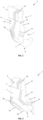
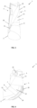
- Fig. 1 shows the stabilizing element 26 of the ankle orthosis 1 from the previous figures, detached from the base body 2.
- the strip-shaped, preferably U-shaped, stabilizing element 26 has a plurality of sections 27, 28, 29, 30, 31, which are arranged at an angle to one another such that the stabilizing element 26, when worn, extends medially and laterally behind an ankle of the wearer up to beyond the ankle and comes to rest under the sole of a wearer's foot in front of the ball of the heel in a metatarsal region. There is no rear connection between the two sections 27, 31 running medially and laterally along the wearer's foot.
- the orthosis 1, i.e. the base body 2 with the stabilizing element 26 remains adaptable to the shape, in particular to the width, of the wearer's foot.
- the medial portion 31, which extends above the wearer's ankle, preferably has a widened portion 33. This increases the contact surface of the stabilizing element 26 and thus further improves the stabilizing effect.
- the portion 28 of the stabilizing element 26, which extends below the wearer's outer ankle preferably has a recess 32 for the ankle. This ensures that the ankle is not overlaid by the stabilizing element 26, which would significantly impair wearing comfort.
- the stabilizing element 26 has an edge 34 in the transition between the plantar side 6 and the lateral side 4 of the base body 2, which serves as an ankle protection.
Landscapes
- Health & Medical Sciences (AREA)
- Nursing (AREA)
- Orthopedic Medicine & Surgery (AREA)
- Engineering & Computer Science (AREA)
- Biomedical Technology (AREA)
- Heart & Thoracic Surgery (AREA)
- Vascular Medicine (AREA)
- Life Sciences & Earth Sciences (AREA)
- Animal Behavior & Ethology (AREA)
- General Health & Medical Sciences (AREA)
- Public Health (AREA)
- Veterinary Medicine (AREA)
- Orthopedics, Nursing, And Contraception (AREA)
Priority Applications (1)
| Application Number | Priority Date | Filing Date | Title |
|---|---|---|---|
| EP23020557.7A EP4574103B1 (fr) | 2023-12-18 | 2023-12-18 | Orthèse de cheville |
Applications Claiming Priority (1)
| Application Number | Priority Date | Filing Date | Title |
|---|---|---|---|
| EP23020557.7A EP4574103B1 (fr) | 2023-12-18 | 2023-12-18 | Orthèse de cheville |
Publications (2)
| Publication Number | Publication Date |
|---|---|
| EP4574103A1 true EP4574103A1 (fr) | 2025-06-25 |
| EP4574103B1 EP4574103B1 (fr) | 2026-03-18 |
Family
ID=89223673
Family Applications (1)
| Application Number | Title | Priority Date | Filing Date |
|---|---|---|---|
| EP23020557.7A Active EP4574103B1 (fr) | 2023-12-18 | 2023-12-18 | Orthèse de cheville |
Country Status (1)
| Country | Link |
|---|---|
| EP (1) | EP4574103B1 (fr) |
Citations (7)
| Publication number | Priority date | Publication date | Assignee | Title |
|---|---|---|---|---|
| WO1987002885A1 (fr) * | 1985-11-12 | 1987-05-21 | Charles Kallassy | Chevillere |
| US20020029009A1 (en) * | 2000-09-05 | 2002-03-07 | Bowman Gerald D. | Rigid ankle and foot orthosis |
| US20060178606A1 (en) * | 2004-10-19 | 2006-08-10 | Aircast, Llc | Devices and methods for adjustable foot correction |
| EP2050429A1 (fr) | 2007-10-18 | 2009-04-22 | Albrecht GmbH | Rail d'articulation de cheville doté d'une ceinture de pronation pourvue d'un coussin à rembourrage liquide massant |
| US8202239B2 (en) * | 2006-09-25 | 2012-06-19 | Gary Blaine Wilkerson | Ankle derotation and subtalar stabilization orthosis |
| EP2666445B1 (fr) | 2012-05-24 | 2015-07-22 | medi GmbH & Co. KG | Orthèse de l'articulation de la cheville |
| US20190015234A1 (en) * | 2017-07-12 | 2019-01-17 | Medical Specialties, Inc. | Brace for Posterior Tibial Tendon Dysfunction |
-
2023
- 2023-12-18 EP EP23020557.7A patent/EP4574103B1/fr active Active
Patent Citations (7)
| Publication number | Priority date | Publication date | Assignee | Title |
|---|---|---|---|---|
| WO1987002885A1 (fr) * | 1985-11-12 | 1987-05-21 | Charles Kallassy | Chevillere |
| US20020029009A1 (en) * | 2000-09-05 | 2002-03-07 | Bowman Gerald D. | Rigid ankle and foot orthosis |
| US20060178606A1 (en) * | 2004-10-19 | 2006-08-10 | Aircast, Llc | Devices and methods for adjustable foot correction |
| US8202239B2 (en) * | 2006-09-25 | 2012-06-19 | Gary Blaine Wilkerson | Ankle derotation and subtalar stabilization orthosis |
| EP2050429A1 (fr) | 2007-10-18 | 2009-04-22 | Albrecht GmbH | Rail d'articulation de cheville doté d'une ceinture de pronation pourvue d'un coussin à rembourrage liquide massant |
| EP2666445B1 (fr) | 2012-05-24 | 2015-07-22 | medi GmbH & Co. KG | Orthèse de l'articulation de la cheville |
| US20190015234A1 (en) * | 2017-07-12 | 2019-01-17 | Medical Specialties, Inc. | Brace for Posterior Tibial Tendon Dysfunction |
Also Published As
| Publication number | Publication date |
|---|---|
| EP4574103B1 (fr) | 2026-03-18 |
Similar Documents
| Publication | Publication Date | Title |
|---|---|---|
| DE102018107183B4 (de) | Dehnbares Element für einen Schuh und Schuh mit dem dehnbaren Elemant | |
| EP1179325B1 (fr) | Bandage pour la cheville | |
| EP1906890B1 (fr) | Bandage pour l'articulation de la cheville | |
| AT396324B (de) | Schuhkonstruktion | |
| EP0499710A2 (fr) | Bandage pour cheville | |
| DE3525753A1 (de) | Fuss-stuetzbandage | |
| EP2835072B1 (fr) | Chaussure orthopédique destinée à empêcher des charges de pression élevées | |
| EP2840918B1 (fr) | Sandale hallux valgus | |
| EP0305999A1 (fr) | Support pour la cheville | |
| EP0485943A1 (fr) | Pelote pour la cheville, chevillère et bandage de la cheville les contenant | |
| EP1280487A1 (fr) | Bandage pour l'articulation du pied | |
| EP4312902B1 (fr) | Orthèse de pied avec segment d'orteil en forme de support pour corriger les malpositions du pied | |
| EP4574103B1 (fr) | Orthèse de cheville | |
| EP4312645B1 (fr) | Chaussures avec sangle élastique correctrice pour le traitement et la prévention des déformations du pied | |
| WO2023169662A1 (fr) | Bas | |
| EP2666445A2 (fr) | Orthèse de l'articulation de la cheville | |
| DE9100531U1 (de) | Fußorthese | |
| EP3417732B1 (fr) | Chaussure dotée d'un dispositif stimulant le pied | |
| EP3417838B1 (fr) | Bande de correction élastique et système de correction des mauvaises positions des orteils d'un pied humain | |
| EP3429514B1 (fr) | Chaussette médicale | |
| DE202011005160U1 (de) | Schuh mit einer Sohle und einem Schaft | |
| DE102020129452A1 (de) | Fussbandage zur entlastung und unterstützung des fusslängsgewölbes einer person | |
| DE20205091U1 (de) | Vorrichtung zur Linderung der beim Gehen von einem Fersensporn verursachten Schmerzen und zur Unterstützung der Fußmuskulatur beim Laufen und Springen | |
| DE2733357A1 (de) | Orthese zur nachbehandlung von vorfussoperationen | |
| WO2016038167A1 (fr) | Orthèse |
Legal Events
| Date | Code | Title | Description |
|---|---|---|---|
| PUAI | Public reference made under article 153(3) epc to a published international application that has entered the european phase |
Free format text: ORIGINAL CODE: 0009012 |
|
| STAA | Information on the status of an ep patent application or granted ep patent |
Free format text: STATUS: THE APPLICATION HAS BEEN PUBLISHED |
|
| AK | Designated contracting states |
Kind code of ref document: A1 Designated state(s): AL AT BE BG CH CY CZ DE DK EE ES FI FR GB GR HR HU IE IS IT LI LT LU LV MC ME MK MT NL NO PL PT RO RS SE SI SK SM TR |
|
| P01 | Opt-out of the competence of the unified patent court (upc) registered |
Free format text: CASE NUMBER: UPC_APP_3042_4574103/2025 Effective date: 20250811 |
|
| STAA | Information on the status of an ep patent application or granted ep patent |
Free format text: STATUS: REQUEST FOR EXAMINATION WAS MADE |
|
| GRAP | Despatch of communication of intention to grant a patent |
Free format text: ORIGINAL CODE: EPIDOSNIGR1 |
|
| STAA | Information on the status of an ep patent application or granted ep patent |
Free format text: STATUS: GRANT OF PATENT IS INTENDED |
|
| 17P | Request for examination filed |
Effective date: 20251126 |
|
| INTG | Intention to grant announced |
Effective date: 20251210 |
|
| GRAS | Grant fee paid |
Free format text: ORIGINAL CODE: EPIDOSNIGR3 |
|
| GRAA | (expected) grant |
Free format text: ORIGINAL CODE: 0009210 |
|
| STAA | Information on the status of an ep patent application or granted ep patent |
Free format text: STATUS: THE PATENT HAS BEEN GRANTED |
|
| AK | Designated contracting states |
Kind code of ref document: B1 Designated state(s): AL AT BE BG CH CY CZ DE DK EE ES FI FR GB GR HR HU IE IS IT LI LT LU LV MC ME MK MT NL NO PL PT RO RS SE SI SK SM TR |
|
| REG | Reference to a national code |
Ref country code: CH Ref legal event code: F10 Free format text: ST27 STATUS EVENT CODE: U-0-0-F10-F00 (AS PROVIDED BY THE NATIONAL OFFICE) Effective date: 20260318 Ref country code: GB Ref legal event code: FG4D Free format text: NOT ENGLISH Ref country code: CH Ref legal event code: R17 Free format text: ST27 STATUS EVENT CODE: U-0-0-R10-R17 (AS PROVIDED BY THE NATIONAL OFFICE) Effective date: 20260318 |
|
| REG | Reference to a national code |
Ref country code: IE Ref legal event code: FG4D Free format text: LANGUAGE OF EP DOCUMENT: GERMAN |
|
| REG | Reference to a national code |
Ref country code: DE Ref legal event code: R096 Ref document number: 502023003378 Country of ref document: DE |