EP4574112A1 - Ophthalmologisches system zur ablativen augenfarbstoffentfernung in der hornhaut eines auges - Google Patents
Ophthalmologisches system zur ablativen augenfarbstoffentfernung in der hornhaut eines auges Download PDFInfo
- Publication number
- EP4574112A1 EP4574112A1 EP24220114.3A EP24220114A EP4574112A1 EP 4574112 A1 EP4574112 A1 EP 4574112A1 EP 24220114 A EP24220114 A EP 24220114A EP 4574112 A1 EP4574112 A1 EP 4574112A1
- Authority
- EP
- European Patent Office
- Prior art keywords
- cornea
- eye
- colorant
- ophthalmological
- area
- Prior art date
- Legal status (The legal status is an assumption and is not a legal conclusion. Google has not performed a legal analysis and makes no representation as to the accuracy of the status listed.)
- Pending
Links
Images


Classifications
-
- A—HUMAN NECESSITIES
- A61—MEDICAL OR VETERINARY SCIENCE; HYGIENE
- A61F—FILTERS IMPLANTABLE INTO BLOOD VESSELS; PROSTHESES; DEVICES PROVIDING PATENCY TO, OR PREVENTING COLLAPSING OF, TUBULAR STRUCTURES OF THE BODY, e.g. STENTS; ORTHOPAEDIC, NURSING OR CONTRACEPTIVE DEVICES; FOMENTATION; TREATMENT OR PROTECTION OF EYES OR EARS; BANDAGES, DRESSINGS OR ABSORBENT PADS; FIRST-AID KITS
- A61F9/00—Methods or devices for treatment of the eyes; Devices for putting in contact-lenses; Devices to correct squinting; Apparatus to guide the blind; Protective devices for the eyes, carried on the body or in the hand
- A61F9/007—Methods or devices for eye surgery
- A61F9/008—Methods or devices for eye surgery using laser
- A61F9/00802—Methods or devices for eye surgery using laser for photoablation
-
- A—HUMAN NECESSITIES
- A61—MEDICAL OR VETERINARY SCIENCE; HYGIENE
- A61F—FILTERS IMPLANTABLE INTO BLOOD VESSELS; PROSTHESES; DEVICES PROVIDING PATENCY TO, OR PREVENTING COLLAPSING OF, TUBULAR STRUCTURES OF THE BODY, e.g. STENTS; ORTHOPAEDIC, NURSING OR CONTRACEPTIVE DEVICES; FOMENTATION; TREATMENT OR PROTECTION OF EYES OR EARS; BANDAGES, DRESSINGS OR ABSORBENT PADS; FIRST-AID KITS
- A61F9/00—Methods or devices for treatment of the eyes; Devices for putting in contact-lenses; Devices to correct squinting; Apparatus to guide the blind; Protective devices for the eyes, carried on the body or in the hand
- A61F9/007—Methods or devices for eye surgery
- A61F9/008—Methods or devices for eye surgery using laser
- A61F9/00802—Methods or devices for eye surgery using laser for photoablation
- A61F9/00812—Inlays; Onlays; Intraocular lenses [IOL]
-
- A—HUMAN NECESSITIES
- A61—MEDICAL OR VETERINARY SCIENCE; HYGIENE
- A61F—FILTERS IMPLANTABLE INTO BLOOD VESSELS; PROSTHESES; DEVICES PROVIDING PATENCY TO, OR PREVENTING COLLAPSING OF, TUBULAR STRUCTURES OF THE BODY, e.g. STENTS; ORTHOPAEDIC, NURSING OR CONTRACEPTIVE DEVICES; FOMENTATION; TREATMENT OR PROTECTION OF EYES OR EARS; BANDAGES, DRESSINGS OR ABSORBENT PADS; FIRST-AID KITS
- A61F9/00—Methods or devices for treatment of the eyes; Devices for putting in contact-lenses; Devices to correct squinting; Apparatus to guide the blind; Protective devices for the eyes, carried on the body or in the hand
- A61F9/007—Methods or devices for eye surgery
- A61F9/008—Methods or devices for eye surgery using laser
- A61F9/00825—Methods or devices for eye surgery using laser for photodisruption
- A61F9/00836—Flap cutting
-
- A—HUMAN NECESSITIES
- A61—MEDICAL OR VETERINARY SCIENCE; HYGIENE
- A61F—FILTERS IMPLANTABLE INTO BLOOD VESSELS; PROSTHESES; DEVICES PROVIDING PATENCY TO, OR PREVENTING COLLAPSING OF, TUBULAR STRUCTURES OF THE BODY, e.g. STENTS; ORTHOPAEDIC, NURSING OR CONTRACEPTIVE DEVICES; FOMENTATION; TREATMENT OR PROTECTION OF EYES OR EARS; BANDAGES, DRESSINGS OR ABSORBENT PADS; FIRST-AID KITS
- A61F9/00—Methods or devices for treatment of the eyes; Devices for putting in contact-lenses; Devices to correct squinting; Apparatus to guide the blind; Protective devices for the eyes, carried on the body or in the hand
- A61F9/007—Methods or devices for eye surgery
- A61F9/008—Methods or devices for eye surgery using laser
- A61F2009/00861—Methods or devices for eye surgery using laser adapted for treatment at a particular location
- A61F2009/00872—Cornea
-
- A—HUMAN NECESSITIES
- A61—MEDICAL OR VETERINARY SCIENCE; HYGIENE
- A61F—FILTERS IMPLANTABLE INTO BLOOD VESSELS; PROSTHESES; DEVICES PROVIDING PATENCY TO, OR PREVENTING COLLAPSING OF, TUBULAR STRUCTURES OF THE BODY, e.g. STENTS; ORTHOPAEDIC, NURSING OR CONTRACEPTIVE DEVICES; FOMENTATION; TREATMENT OR PROTECTION OF EYES OR EARS; BANDAGES, DRESSINGS OR ABSORBENT PADS; FIRST-AID KITS
- A61F9/00—Methods or devices for treatment of the eyes; Devices for putting in contact-lenses; Devices to correct squinting; Apparatus to guide the blind; Protective devices for the eyes, carried on the body or in the hand
- A61F9/007—Methods or devices for eye surgery
- A61F9/008—Methods or devices for eye surgery using laser
- A61F2009/00897—Scanning mechanisms or algorithms
Definitions
- the present disclosure relates to an ophthalmological system for ablative removal of eye colorant arranged in a cornea of an eye of a patient and to a computer program product comprising a non-transitory computer-readable medium having stored thereon computer program core for controlling a processor of the ophthalmological system for ablative removal of eye colorant.
- the present disclosure relates in particular to an ophthalmological system comprising a laser source, focusing optics, a scanner system and an electronic circuit, which is configured to control the ophthalmological device.
- US patent US 7,621,637 B2 describes exemplarily an apparatus for working on eye tissue, said apparatus having a base station with a laser source for producing laser pulses and a scanner, arranged in the base station, with movable deflection mirrors for deflecting the laser pulses in a scan direction.
- the deflected laser pulses are transferred via an optical relay system from the base station to an application head, the latter passing over a work region according to a scan pattern by means of a mechanically moved projection optical unit.
- ophthalmological devices For processing or creating a pocket in the eye tissue, ophthalmological devices are known, such as scalpels or laser systems, which use scanner systems with multiple scan axes.
- the conventional available scanner systems enable to create a pocket within the cornea e.g. for removing a lenticule or for inserting a lens or for inserting cornea material.
- Each person has an individual iris color distribution and iris color structure.
- the individual color and structure of the iris is determined by an individual composition of pigments across the iris of the eye.
- the eye color distribution of humans varies normally from dark brown to light blue. Different pigment concentrations on different areas of the iris may further determine the individual appearance of the iris. For example, a light blue center of the iris may be surrounded by a darker ring on the peripheral part of the iris.
- a colored implant on the iris or to depigment the iris with a laser beam. Both chirurgical methods are dangerous for the iris and in particular, the second one is limited with respect to only brightening the already existing iris.
- Another possibility to amend the visual appearance of the iris is to place in the cornea of the respective eye, thus in front of the iris, ink, such that the ink covers partially or entirely the natural color of the iris. Over time, the ink or eye colorant within the cornea may bleach or fades out. In addition, the ink may slowly move into other regions or the cornea, which affect the visual appearance and could harm the eye of the patient. A removal or replacement of the eye colorant or ink might be necessary.
- the eye colorant or ink is removed manually by a medical professional, which opens the cornea for access to the respective region and which scrapes out the respective colorant material.
- This uncontrolled procedure is often additionally affects cornea tissue negatively which is healthy and should not be affected. Further, the procedure may harm the entire eye because the eye itself offers no boarders for the medical professional.
- the areas in the cornea comprising the eye colorant are conventionally determined by the medical professional, which is not very accurate, resulting in remaining eye colorant in the cornea after the removal procedure.
- an ophthalmological system for ablative removal of eye colorant arranged in a cornea of an eye of a patient preferably comprises a position measurement system, a laser source, a focusing optics, a scanner system and an electronic circuit.
- the position measurement system is configured to determine an area in the cornea comprising the eye colorant, preferably using image information of the cornea.
- the position measurement system is a system, which is configured to measure the eye of the patient, in particular to determine, which portions or areas of the eye tissue form which part of the eye, e.g. cornea, sclera, lens etc.
- the positon measurement system is configured to determine an area or a plurality of areas in the cornea comprising the eye colorant.
- the output of the position measurement system may be reference data describing the position of the eye colorant within the cornea and / or the position of the cornea within the respective eye.
- the laser source is configured to generate a pulsed laser beam and the focusing optics is configured to make the pulsed laser beam converge onto a focal spot in the cornea and the scanner system is configured to deflect the pulsed laser beam to target locations in the cornea.
- the scanner system may comprise only one scanner assembly arranged in one housing, which provides the required functionalities. In another embodiment, the scanner system may comprise a plurality of scanner assemblies arranged in one or a plurality of housings, which provide in combination with each other the required functionality.
- the ophthalmological system further comprises an electronic circuit configured to control the scanner system to direct the focal spot to process the determined area comprising the eye colorant in the cornea for ablative removal of the eye colorant arranged in the cornea.
- the electric circuit controls the scanner system to direct the focal spot such that the area of the cornea comprising the eye colorant is processed.
- Processing means that the laser energy is focused on the eye colorant, in particular on the area, comprising the eye colorant, such that the eye colorant is removed, in particular vaporized.
- the position measurement system is configured to determine the area comprising the eye colorant in a very precise manner. In particular, the position measurement system uses algorithms and / or input form medical professionals, for determining of the eye colorant comprising areas. E.g.
- the positions measurement system advantageously provides accurate three-dimensional position information of eye colorant within the cornea of the eye, which is desired to be removed.
- the position measurement system may comprise a video capturing system (color camera), an optical coherence tomography (OCT) system, a scheimpflug device, and/or a structured light illumination system, which are configured to provide measurement data.
- the position measurement system may show a picture of the cornea to the medical professional, which determines solely or with the aid of the position measurement system software the area comprising the eye colorant.
- the position measurement system may provide a preselection of an area comprising the eye colorant, which may be modified or adapted by the medical professional.
- the result e.g. the geometric position reference data, which determines the area comprising eye colorant is further used by the ophthalmological system for the ablative removal of the eye colorant.
- the position measurement system may be a standalone system, which is not directly integrated in the ophthalmologic device, which comprises the laser source, scanner system etc.
- the laser source of the ophthalmological system used for ablative removal of the eye colorant comprises a solid-state laser source, excimer laser source and/or a femtosecond laser source.
- the laser source is in particular configured to provide the pulsed laser beam with the required laser power for the ablative removal of the eye colorant. Different eye colorants may require different laser parameters for an optimized removal.
- the laser source is preferably configurable such that the eye colorant is ablatively removable by the laser source.
- the position measurement system is configured to determine a thickness and / or a depth position of the area comprising the eye colorant within the cornea, and wherein the electronic circuit is configured to move the focal spot to process the determined area using the determined thickness and / or depth position of the area comprising the eye colorant.
- the depth position is the position in z-direction within the cornea.
- the eye colorant is not formed as a layer having an infinite small thickness. To the contrary, the eye colorant has a defined thickness and possibly also a varying thickness across the cornea. In order to affect as little cornea tissue as possible it is highly desirable to determine the thickness and depth position of the area comprising the eye colorant. This is in particularly advantageous determinable by the position measurement system comprising an OCT System.
- the area comprising the eye colorant is determined three-dimensional, which enables to advantageously ablatively remove the eye colorant. Thicker segments of the area are e.g. processed several times and thinner segments of the area are e.g. processed only once.
- the predetermined processing path is determined by the electronic circuit accordingly. Further, it is also conceivable that the laser power or other parameters of the laser are adjusted based on the determined thickness of the eye colorant, in particular such that the eye colorant may be advantageously entirely ablatively removed.
- the position measurement system is configured to determine the thickness and / or a depth position of the area comprising the eye colorant within the cornea during processing or treating of the cornea, in particular continuously, such that treating, in particular the ablative removal of the eye colorant, is monitored, in particular continuously further using the thickness and / or depth position of the area comprising the eye colorant. It is thereby possible that the treating, in particular the ablative removal of the eye colorant, is monitored by the electronic circuit further using the thickness and or the depth position.
- the determined actual thickness or depth position data may be matched to expected data, in particular expected thickness or depth position reference data.
- the electronic circuit might adjust the control data for the scanner system or the entire ophthalmological system, in particular in real time. Further, in case the thickness of the area comprising the eye colorant reaches zero or close to zero, the processing of the respective portion is stopped and may continue at another portion. Further, an additional buffer of cornea tissue in z-direction may additionally be treated such that the eye colorant is advantageously removed completely.
- the electronic circuit is further configured to control the scanner system to move the focal spot to form a cut extending at least partially from the outer surface of the cornea into the cornea, thereby forming a cornea flap, which is moveable for providing direct access to the area comprising the eye colorant in the cornea.
- the area comprising the eye colorant is laid open or uncovered by forming the cornea flap.
- the cornea flap is the portion of the cornea, which at least partially covers the eye colorant when viewed along the z-direction of the eye towards the eye. It may be required that this portion of the cornea is unaffected by the ablative removal of the eye colorant.
- forming the cut and flapping the resulting cornea flap away could be used.
- the cut or the plurality of cuts, in particular the respective processing paths for forming the cornea flap is e.g. automatically determined by the electronic circuit using the position data of the area comprising the eye colorant from the position measurement system. It is to be noted that it is also possible to focus the pulsed laser beam through the cornea for ablative removal of the eye colorant without providing direct access. Forming the cornea flap and flipping the cornea flap away for direct access is optional. In case no cornea flap is formed, a venting access to the eye colorant may be formed enabling that the vaporized eye colorant may stream advantageously out of the cornea. The venting access may additionally be used for cleaning of the resulting cavity in the cornea.
- the eye of the patient is a three dimensional object, which extends in three space direction, in particular in the x-, y- and the z-direction.
- the z direction is e.g. parallel with respect to the symmetry axis of the eye, parallel with respect to the visual axis of the eye or parallel with respect to a virtual axis extending crossing the center of the pupil and the apex of the cornea.
- the z-direction might be perpendicular arranged to a plane of the eye, in particular the pupil plane of the eye.
- the x-y direction might be arranged such that a virtual plane, which is determined by the x and y direction is arranged coplanar or parallel with the iris or pupil plane. Other definitions might also be conceivable.
- the ophthalmological device, which is used for cutting the cornea flap corresponds to the ophthalmological device, which is used for the ablative removal of the eye colorant.
- a single ophthalmological device is used for cutting the cornea flap and for processing the area comprising the eye colorant by ablative removal.
- the ophthalmological system further comprises an access device configured to form the cut in the cornea, which extends from an outer surface of the cornea into the cornea thereby forming the cornea flap, which is moveable for providing direct access to the area comprising the eye colorant in the cornea.
- an access device configured to form the cut in the cornea, which extends from an outer surface of the cornea into the cornea thereby forming the cornea flap, which is moveable for providing direct access to the area comprising the eye colorant in the cornea.
- the access device is e.g. a surgical scalpel, a mikroceratom and/or a trepanic device.
- the access device is provided by a standalone access cutting ophthalmological device comprising a respective position measurement system, a respective laser source configured to generate a pulsed laser beam, a focusing optics configured to make the pulsed laser beam converge onto a focal spot in the cornea and a scanner system configured to deflect the pulsed laser beam to target locations in the cornea.
- This standalone access cutting ophthalmological device may additionally comprise an electronic circuit configured to control the scanner system to move the focal spot inside the cornea to form the cut extending at least partially from the outer surface of the cornea into the cornea, thereby forming the cornea flap, which is moveable for providing direct access to the area comprising the eye colorant.
- This standalone access cutting ophthalmological device may deviate from the ablative ophthalmological device in the laser source.
- the laser source of the access cutting ophthalmological device is selected for an advantageous cutting and the laser source of the ablative ophthalmological device is selected for an advantageous ablative removal. Both devices form part of the ophthalmological system.
- the position measurement system may be a standalone device or is integrated in the access cutting ophthalmological device. In case the position measurement system is a standalone device, the data from it may be provided to the access cutting ophthalmological device and the ablative ophthalmological device, in particular via a wired or wireless connection.
- the laser source of the access cutting ophthalmological device comprises a femtosecond laser source for producing femtosecond laser pulses, a solid-state laser source and/or an excimer laser source.
- the femtosecond laser source advantageously provides the desired laser properties for forming the cut in the cornea.
- the electronic circuit is configured to control the scanner system to move the focal spot inside the cornea to generate an at least partially annulus shaped cut, thereby forming an at least partially annulus shaped cornea flap, which is moveable for providing direct access to the eye colorant comprising location, and which keeps the center portion of the cornea unaffected.
- the eye colorant is most of the times arranged such that it covers the iris of the eye.
- the eye colorant has therefore the shape of a ring or annulus when viewed along the z-direction of the eye towards the eye.
- the center portion of the cornea, in particular the pupil portion is normally free of eye colorant. This center portion is also the most important one regarding the visual sight of the eye.
- the center portion is unaffected by the ablative removal and the forming of the cut for the flap.
- the center portion is spared during forming of the cornea flap.
- the electronic circuit is configured to control the scanner system to move the focal spot inside the cornea to generate the cut such the cut is arranged adjacent to the area comprising the eye colorant.
- the electronic circuit is in particular configured to control the scanner system such that the cut is immediately arranged adjacent to the area comprising the eye colorant.
- the eye colorant is distributed three-dimensional within the cornea, e.g. having thicker and thinner portions. In order to ablatively remove the eye colorant advantageously it is desired to place the cut also three-dimensional adjacently above the eye colorant.
- the cut has e.g. the shape of the top surface of the area comprising the eye colorant.
- the electronic circuit is configured to control the scanner system to move the focal spot inside the cornea to generate the cut such the cut is arranged with a predetermined offset to the area comprising the eye colorant.
- the cut is formed at the offset, of e.g. 5-100 micrometers, away from the area comprising the eye colorant towards the anterior surface of the cornea.
- eye colorant may remain arranged on the bottom side of the cornea flap.
- This eye colorant might be additionally removed ablatively via a laser by a respective ophthalmological device, in particular the ablative ophthalmological device.
- the ophthalmological system and / or the access cutting ophthalmological device comprise a patient interface, with a contact body, which contact body brings an outer surface of the cornea in an applanated form in a state where the patient interface is applied on the eye, and the electronic circuit is configured to control the respective scanner system to move the focal spot at locations on the applanated locations of the cornea comprising at least partially the eye colorant and / or to move the focal spot inside the cornea to generate the cut extending at least partially from the outer surface of the cornea into the cornea, thereby forming the cornea flap.
- the patient interface may be used for the ablative removal and / or for cutting of the flap. It is also conceivably that the patient interface remains for both procedures the same and only the ophthalmological device is switched.
- the contact body may compensate deviations in the outer shape of the cornea for forming the desired cut and for processing the desired area.
- the electronic circuit of the ophthalmological system or the electronic circuit of the access cutting ophthalmological device is configured to control the respective scanner system to move the focal spot along a surface of the cornea, which was previously at least partially covered by the eye colorant for leveling the surface of these locations.
- the removal of the eye colorant may leave a cavity in the cornea, having at least partially the shape of the removed area. It might be desired to process the cavity, in particular to level the cavity such that the cornea may heal advantageously after treatment and that the eyesight is as unaffected as possible.
- a computer program product comprising a non-transitory computer-readable medium having stored thereon computer program code for controlling a processor of an ophthalmological system for ablative removal of eye colorant arranged in a cornea of an eye of a patient.
- the ophthalmological system comprises preferably a position measurement system configured to determine an area in the cornea comprising the eye colorant, preferably using images of the cornea, a laser source configured to generate a pulsed laser beam, a focusing optics configured to make the pulsed laser beam converge onto a focal spot in the cornea, a scanner system configured to deflect the pulsed laser beam to target locations in the cornea.
- the computer program code is configured to control the processor such that the processor directs the focal spot of the scanner system to process the determined area comprising at least partially the eye colorant for ablative removal of the eye colorant arranged in the cornea of the eye.
- the computer program code is further configured to control the processor such that the processor directs the ophthalmological system, in particular the ablative ophthalmological device and / or the flap cutting ophthalmological device as described above and hereinafter.
- the person skilled in the art will understand that by controlling the ophthalmological system 100, in particular its components, respectively, it is possible to process three-dimensional (tissue) pieces in particular by ablatively removing eye tissue or material arranged in the cornea 202, e.g. predetermined areas 205, which may comprise eye colorant 204 as material in the eye 201. It is of course further possible to form three-dimensional cuts or pockets in the eye tissue.
- the person skilled in the art will further understand that by controlling the ophthalmological system 100, in particular its components, respectively, it might be further possible to achieve three-dimensional volume treatment of the eye tissue, e.g. for generating a pocket, a void volume inside the eye tissue e.g. the cornea 202.
- the ophthalmological system 100 comprises a laser source 102 for generating the pulsed laser beam T, a focusing optics 103 for focusing or making the pulsed laser beam T converge onto a focal spot S in or on the eye tissue, and a scanner system 104 for moving the focal spot S to target locations in and/or on the eye tissue, in particular configured to deflect the pulsed laser beam T to target locations in the cornea 202.
- the ophthalmological system 100 further comprises an electronic circuit 105 for controlling the ophthalmological system 100, in particular the laser source 102 and the scanner system 104.
- the electronic circuit 105 implements a programmable control device and comprises e.g. one or more processors 106 with program and data memory and programmed software modules for controlling the processors 106, and/or other programmable circuits or logic units such as ASICs (application specific integrated circuits) or the likes.
- a functional part of the electronic circuit 105 is arranged in a separate housing and implements a further programmable control device 105, e.g. a computer system, comprising e.g.
- processors 106 with program and data memory and programmed software modules for controlling the processors 106, and/or other programmable circuits or logic units such as ASICs or the like.
- a communication link might be required, which comprises one or more electrical connections, an electronic bus, a wired communication network, and/or a wireless communication network.
- the laser source 102 comprises a solid-state laser source or an excimer laser source.
- the laser source 102 is arranged in a separate housing or in a housing shared with the focusing optics 103.
- the focusing optics 103 is configured to focus the pulsed laser beam T or the laser pulses, respectively, onto a focal spot S in or on the eye tissue, i.e. for making the pulsed laser beam T converge to a focus or focal spot in or on the eye tissue.
- the focusing optics or optical module 103 comprises one or more optical lenses.
- the focusing optics 103 comprises a focus adjustment device for setting the focal depth of the focal spot S, for example one or more movable lenses, in the focusing optics 103 or upstream of the focusing optics 103, or a drive for moving the entire optics 103 along the projection axis p (z-axis).
- the focusing optics 103 is installed in an application head 107, which can be placed onto the eye 201.
- the person skilled in the art will understand that in cases where the focusing optics 103 is adjusted (focus) or moved as part of the scanning process or scanning actuation, the focusing optics 103 and associated drives (actuators) can be viewed and considered as parts of the scanner system 104, implementing a z-scanner configured to modulate the depth z of the focal spot S along the projection axis p or the eye symmetry axis q.
- the contact body 121 also referred to as applanation body, is at least partly light-transparent. In the state where the patient interface 120 or the contact body 121, respectively, is fixed to the cornea 202, the cornea 202 is applanated where the contact body 121 is in contact with the exterior (anterior) surface of the cornea 202.
- the ophthalmological system 100 further comprises a position measurement system 101 configured to determine positional reference data of the cornea 202.
- the position measurement system 101 may comprise a video capturing system, an optical coherence tomography (OCT) system, and/or a structured light illumination system.
- OCT optical coherence tomography
- the measurement data or positional reference data determined by the position measurement system 101 includes video data, including top view data (comprising two-dimensional images), and/or OCT data of the eye 201, in particular of the cornea 202 (comprising three-dimensional data, in particular three-dimensional tomography data).
- the position measurement system 101 is configured to determine the positional reference data of the cornea 202 also in an applanated state of the cornea 202.
- the position measurement system 101 is according to the embodiment shown in Figure 1 connected to and/or integrated with the electronic circuit 105, which is further configured to control ophthalmological system 100, in particular the scanner system 104, using the data, in particular the positional reference date or further data, from the position measurement system 101.
- the electronic circuit 105 is configured to use treatment control data to control the ophthalmological device 100, in particular the scanner system 104 to move the focal spot S in or on the eye tissue to target locations along a processing path 160 defined by the treatment control data for treating in and/or on the eye tissue.
- the treatment control data is e.g. determined by the electronic circuit 105 using the position reference data from the position measurement system 101, stored in the data memory and/or data store of the electronic circuit 105 and/or received via a communication link from a separate computer system.
- the position measurement system 101 is at least configured to determine an area 205 in the cornea 202, which comprises at least partially the eye colorant 202.
- the output of the position measurement system 101 is e.g. position reference data of the area 205 comprising eye colorant 202.
- the electronic circuit 105 is configured to determine treatment control data, in particular data for at least one processing path 160 along which the scanner system 104 moves the focal spot S or a scan line for treating the eye tissue, in particular for ablatively removing the eye colorant.
- the orientation, arrangement, geometrical parameters and physical parameters of the focal spot S or a scan line along the predetermined processing paths 160 might also be determined by the treatment control data.
- the treatment control data defines a sequence of consecutive target locations in a three-dimensional x/y/z-space for treating e.g. a three-dimensional area in the cornea 202.
- the treatment control data comprises path definition data, e.g. coordinates, positions, positional references, etc., and/or path processing data, e.g. instructions, operations, and/or procedures for the scanner system 104 and its components, described below in more detail.
- the at least one processing path 160 or the sub-processing paths 161 can be defined as a trajectory for the focal spot S or the scan line, to be moved along by the scanner system 104 for treating the cornea 202.
- the treatment control data may further comprise control data for controlling the laser source 102 e.g. for controlling physical parameters of the pulsed laser beam T like processing speed, pulse rate, pulse energy, etc..
- the scanning requirements include a depth-scanning requirement, representing the required modulation of the depth z of the focal spot S when moved along the processing path 160 defined in particular by the treatment control data.
- the depth-scanning requirement includes the dynamics required for the modulation of the depth z of the focal spot S, the scan line 130 respectively along the processing path 160 defined in particular by the treatment control data.
- the required depth scanning dynamics may comprise the required depth scanning speed, the required depth scanning frequency, the required amplitude of depth modulation at a particular speed of the depth modulation, the required amplitude of depth modulation at a particular frequency of the depth modulation, the required acceleration of the depth modulation, and/or the required speed of the acceleration of the depth modulation.
- Treating of eye tissue, in particular of the cornea 202 may comprise to ablatively remove the eye colorant 204 and / or adjacent cornea tissue, and to form cuts 208 or pockets in the cornea 202. Treating is e.g. a collective term.
- the ophthalmological system 100 as shown in Figure 1 is e.g. used as ablative ophthalmological device 140 for ablative removal of eye colorant 204 arranged in the cornea. Further, the ophthalmological system 100 may additionally be used as access device 150, in particular as access cutting ophthalmological device 151.
- the position measurement system 101 is included in one device. In other words, the ophthalmological system 100 as shown in Figure 1 combines the ablative ophthalmological device 140, the position measurement system 101 and the access device 150 in one ophthalmological device.
- the access cutting ophthalmological device 151 may also comprise the position measurement system 101', the laser source 102', the focusing optics 103', the scanner system 104', the electronic circuit 105' etc. as indicated in Figure 1 .
- FIG. 2 shows another embodiment of an ophthalmological system 100.
- the ophthalmological system 100 comprises three separate devices, namely the position measurement system 101, the access cutting ophthalmological device 151 and the ablative ophthalmological device 140.
- the data from the positon measurement system 101 is advantageously transmitted to the access cutting ophthalmological device 151, such that the desired cornea flap 207 may be formed, and the data from the position measurement system 101 is additionally preferably transmitted to the ablative ophthalmological device 140 such that determined area 205 can be processed for ablative removal as desired.
- the patient 200 is e.g. measured by the position measurement system 101 and at a later point in time, e.g.
- the patient 200 is treated by the access cutting ophthalmological device 151, for cutting the cornea flap 207, the access cutting ophthalmological device 151 is moved away and the ablative ophthalmological device 140 is positioned respectively for the ablative treatment, in particular the ablative removal of eye colorant 205.
- the patient interface 120 arranged on the eye 201 of the patient is not changed.
- the respective application head 107 of both devices is attached respectively.
- a combination of the embodiments is of course also conceivable.
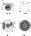
- Figure 3 shows an eye 201 of a patient 200 along the z-axis when viewed towards the eye 201.
- the eye 201 comprises the iris 203 centrally arranged and the cornea 202 arranged above the iris 203 and the pupil of the eye 201.
- Figure 3 further indicates an area 205 of the cornea 203, which comprises the eye colorant 204.
- the area 205 has according to this embodiment an elliptical shape and was inserted e.g. for covering a defect in the iris 203 at the respective positon.
- the area 205 comprising eye colorant 204 is e.g. determined by the position measurement system 101.
- Figure 4 shows a cross section view of the eye 201 of the patient as shown in Figure 3.
- Figure 4 shows the cornea 202 of the patient 200, which comprises the area 205 comprising the eye colorant 204.
- Figure 4 shows advantageously that the eye colorant 204 is arranged partially above the iris 203 for covering partially the iris 203 when viewed along the z-axis towards the eye 201.
- the entire iris 203 may be covered by eye colorant 204.
- Figure 5 shows a first detailed view of the eye 201 of a patient 200 according to another embodiment.
- the cornea 202 comprises two areas 205, which comprise eye colorant 205.
- the eye colorant 205 was e.g. inserted for covering the respective portions of the iris 203. Now, the eye colorant 205 may needs to be removed or replaced.
- Figure 5 additionally indicates a processing path 160, in particular two sub processing paths 161 one for each area 205 along which the focal spot S or a respective scan line is moved for processing, in particular for ablative removal of the eye colorant 204.
- Both sub-processing path 161 comprise a plurality of parallel lines along which the focal spot S is moved for ablative removal of the eye colorant 204.
- Figure 6 shows a second detailed view of the eye 201 of a patient 200 according to another embodiment.
- the area 205 comprising the eye colorant 204 has a ring shape or an annulus shape and covers almost the entire iris 203 of the eye.
- Figure 6 further indicates the processing path 160, which comprises a plurality of concentric arranged circles. A spiral shape or any other shape would of course also be conceivable.
- the area 205 may be processed several times in order to process the area 205 throughout its entire thickness.
- Figure 7 shows a sequence of Figures from Figure 7a to Figure 7e , which shows the process for ablative removal of eye colorant 204 according to a first embodiment.
- the Figures 7a to 7 c show the process of forming or cutting of the cornea flap 207 using e.g. the access cutting ophthalmological device 151.
- Figure 7a shows the eye 201 comprising the eye colorant 204 in the respective area 205 for covering the iris 203.
- Figure 7a indicates a pulsed laser beam T from the access cutting ophthalmological device 151 for forming or cutting the cornea flap 207.
- Figure 7b shows the forming of the cornea flap 207, in particular, a cut through the cornea 202 partially along the upper surface of the eye colorant 204 is indicated by dashed lines.
- Figure 7c shows the eye 201 with the finished formed cornea flap 207.
- Figure 7d shows the eye 201 being treated by the ablative ophthalmological device 140.
- the cornea flap 207 which is according to this embodiment not completely separated from the rest of the eye tissue, is flipped away, which exposed the eye colorant 204, in particular the eye colorant comprising surface 206.
- the pulsed laser beam T of the ablative ophthalmological device 140 is moved along the processing path 160 for treating, in particular for ablatively removing the eye colorant 204.
- eye colorant 204 may remain on the underside of the cornea flap 207. This eye colorant may further be removed by a respective pulsed laser beam T prior of flipping or moving the cornea flap 207 back on the cornea 202. In case some eye colorant 204 remains on the cornea flap 207, the cornea flap 207 may be completely removed from the rest of the cornea 202 and treated at a different place with a respective puled laser beam from a respective ophthalmological device.
- Figure 7e shows the eye 201 after the ablative removal and after the cornea flap 207 has been flipped back.
- new eye colorant 204 may be inserted, in particular into the cavity, which is left behind by the removed eye colorant 204 and removed cornea tissue, in particular prior of flipping the cornea flap 207 back.
- Figure 8 shows a sequence of Figures from Figure 8a to 8e , which shows the process for ablative removal of eye colorant 204 according to a second embodiment.
- This embodiment differs from the embodiment shown in Figure 7 at least in the shape of the cornea flap 207.
- the cornea flat 207 according to Figure 8 is formed by the access cutting ophthalmological device 151 and has an annulus or ring shape.
- the center area of the cornea 202 is spared by the pulsed laser beam T.
- the cornea flap 207 is only formed along the top surface 206 of the eye colorant 204 (including access cuts from the outer surface of the cornea 209).
- Figure 8b show the process of forming the respective annulus shaped cornea flap 207 and Figure 8c shows the finished cornea flap 207 still on the eye colorant 204.
- Figure 8d shows the annulus shaped cornea flap 207 flipped away exposing the eye colorant 204, in particular exposing the eye colorant comprising surface 206.
- Figure 8d further shows the pulsed laser beam T from the ablative ophthalmological device 140 moving along the processing path 160 for ablatively removing the eye colorant 204.
- Figure 8e shows the eye 201 after the ablative removal and after the cornea flap 207 has been flipped back.
- Figure 9 shows a cross section of an eye 201 of a patient 200.
- the cross section indicates in particular the pulsed laser beam following the processing path 160 according to a first embodiment.
- Figure 9 shows in particular the iris 203, the cornea 202, the sclera the limbus of the eye 201 and the eye colorant 204 arranged in the cornea 202.
- Figure 9 shows that the processing paths 160 follow the contour of the cornea 202. In other words, the processing paths 160 have different depth positions or positions in z-direction from the peripheral portion of the cornea 202 towards the center area of the cornea 202.
- the embodiment shown right deviates from the previously mentioned embodiment in that the patient interface 120 does not comprise a contact body.
- a liquid solution is arranged in the patient interface 120 in particular between the application head 107 and the outer surface 209 of the cornea 202.
- This embodiment of the patient interface might be called liquid interface.
Landscapes
- Health & Medical Sciences (AREA)
- Ophthalmology & Optometry (AREA)
- Heart & Thoracic Surgery (AREA)
- Vascular Medicine (AREA)
- Optics & Photonics (AREA)
- Surgery (AREA)
- Engineering & Computer Science (AREA)
- Biomedical Technology (AREA)
- Physics & Mathematics (AREA)
- Nuclear Medicine, Radiotherapy & Molecular Imaging (AREA)
- Life Sciences & Earth Sciences (AREA)
- Animal Behavior & Ethology (AREA)
- General Health & Medical Sciences (AREA)
- Public Health (AREA)
- Veterinary Medicine (AREA)
- Eye Examination Apparatus (AREA)
Applications Claiming Priority (1)
| Application Number | Priority Date | Filing Date | Title |
|---|---|---|---|
| CH14562023 | 2023-12-21 |
Publications (1)
| Publication Number | Publication Date |
|---|---|
| EP4574112A1 true EP4574112A1 (de) | 2025-06-25 |
Family
ID=89620628
Family Applications (1)
| Application Number | Title | Priority Date | Filing Date |
|---|---|---|---|
| EP24220114.3A Pending EP4574112A1 (de) | 2023-12-21 | 2024-12-16 | Ophthalmologisches system zur ablativen augenfarbstoffentfernung in der hornhaut eines auges |
Country Status (2)
| Country | Link |
|---|---|
| US (1) | US20250205085A1 (de) |
| EP (1) | EP4574112A1 (de) |
Citations (5)
| Publication number | Priority date | Publication date | Assignee | Title |
|---|---|---|---|---|
| WO1995003017A1 (en) * | 1993-07-22 | 1995-02-02 | Robbins Allan M | Ocular colorization process for changing eye color |
| US6090100A (en) * | 1992-10-01 | 2000-07-18 | Chiron Technolas Gmbh Ophthalmologische Systeme | Excimer laser system for correction of vision with reduced thermal effects |
| US7621637B2 (en) | 2005-06-09 | 2009-11-24 | Sie Ag Surgical Instrument Engineering | Ophthalmologic device for breaking down eye tissue |
| US20140107631A1 (en) * | 2012-10-12 | 2014-04-17 | Francis FERRARI | Annular keratopigmentation systems and methods of vision correction of presbyopic eyes |
| US20200229975A1 (en) * | 2017-06-07 | 2020-07-23 | Neoris | Devices and method for preparing and carrying out corneal tattoos |
-
2024
- 2024-12-16 EP EP24220114.3A patent/EP4574112A1/de active Pending
- 2024-12-18 US US18/985,402 patent/US20250205085A1/en active Pending
Patent Citations (5)
| Publication number | Priority date | Publication date | Assignee | Title |
|---|---|---|---|---|
| US6090100A (en) * | 1992-10-01 | 2000-07-18 | Chiron Technolas Gmbh Ophthalmologische Systeme | Excimer laser system for correction of vision with reduced thermal effects |
| WO1995003017A1 (en) * | 1993-07-22 | 1995-02-02 | Robbins Allan M | Ocular colorization process for changing eye color |
| US7621637B2 (en) | 2005-06-09 | 2009-11-24 | Sie Ag Surgical Instrument Engineering | Ophthalmologic device for breaking down eye tissue |
| US20140107631A1 (en) * | 2012-10-12 | 2014-04-17 | Francis FERRARI | Annular keratopigmentation systems and methods of vision correction of presbyopic eyes |
| US20200229975A1 (en) * | 2017-06-07 | 2020-07-23 | Neoris | Devices and method for preparing and carrying out corneal tattoos |
Also Published As
| Publication number | Publication date |
|---|---|
| US20250205085A1 (en) | 2025-06-26 |
Similar Documents
| Publication | Publication Date | Title |
|---|---|---|
| KR101476760B1 (ko) | 굴절교정 안과 수술용 시스템 | |
| KR101487895B1 (ko) | 안과굴절교정용 재치료 | |
| RU2498789C2 (ru) | Устройство для воздействия на глаз лазерным излучением | |
| JP6748198B2 (ja) | 屈折矯正眼手術用の切除レーザーのセンタリング法 | |
| US11833080B2 (en) | Planning device and method for generating control data for an ophthalmological laser therapy device for structures bridging the cornea in a pressure-reducing manner | |
| AU2016202852A1 (en) | System, interface devices, use of the interface devices and method for eye surgery | |
| CA2840496A1 (en) | Apparatus and method for a laser-assisted eye-surgery treatment system | |
| KR101644503B1 (ko) | 인간의 각막에 절개를 형성하기 위한 장치 및 방법 | |
| EP3988063B1 (de) | Ophthalmologische vorrichtung zur chirurgischen behandlung einer hornhaut | |
| CN107072816B (zh) | 眼外科手术方法 | |
| EP4574112A1 (de) | Ophthalmologisches system zur ablativen augenfarbstoffentfernung in der hornhaut eines auges | |
| EP4018982B1 (de) | Ophthalmologische vorrichtung zur chirurgischen behandlung einer hornhaut | |
| US20250248849A1 (en) | Ophthalmological Device for Surgical Treatment of a Cornea of an Eye and Computer Program Product for Controlling a Processor of the Ophthalmological Device | |
| EP4201382B1 (de) | Ophthalmologische vorrichtung zur bearbeitung einer gekrümmten behandlungsfläche | |
| US12239577B2 (en) | Ophthalmological device for treatment of a cornea | |
| EP4079267B1 (de) | Ophthalmologische vorrichtung zur behandlung einer hornhaut | |
| JP4863584B2 (ja) | 眼科レーザ手術装置 | |
| EP4018980B1 (de) | Ophthalmologische vorrichtung zur behandlung einer hornhaut | |
| US20240315873A1 (en) | Method for locating visual axis for laser assisted ophthalmic procedure without corneal marking | |
| JP3872228B2 (ja) | レーザ手術装置 | |
| CN121752230A (zh) | 用于生成至少一个切割面的装置和方法、用于生成控制数据的装置和方法 |
Legal Events
| Date | Code | Title | Description |
|---|---|---|---|
| PUAI | Public reference made under article 153(3) epc to a published international application that has entered the european phase |
Free format text: ORIGINAL CODE: 0009012 |
|
| STAA | Information on the status of an ep patent application or granted ep patent |
Free format text: STATUS: THE APPLICATION HAS BEEN PUBLISHED |
|
| AK | Designated contracting states |
Kind code of ref document: A1 Designated state(s): AL AT BE BG CH CY CZ DE DK EE ES FI FR GB GR HR HU IE IS IT LI LT LU LV MC ME MK MT NL NO PL PT RO RS SE SI SK SM TR |
|
| STAA | Information on the status of an ep patent application or granted ep patent |
Free format text: STATUS: REQUEST FOR EXAMINATION WAS MADE |
|
| 17P | Request for examination filed |
Effective date: 20251208 |