EP4574189A1 - Sicherheitssystem für eine spritze und arzneimittelabgabevorrichtung mit solch einem sicherheitssystem - Google Patents
Sicherheitssystem für eine spritze und arzneimittelabgabevorrichtung mit solch einem sicherheitssystem Download PDFInfo
- Publication number
- EP4574189A1 EP4574189A1 EP23307366.7A EP23307366A EP4574189A1 EP 4574189 A1 EP4574189 A1 EP 4574189A1 EP 23307366 A EP23307366 A EP 23307366A EP 4574189 A1 EP4574189 A1 EP 4574189A1
- Authority
- EP
- European Patent Office
- Prior art keywords
- plunger rod
- safety system
- rod cover
- longitudinal axis
- coupling members
- Prior art date
- Legal status (The legal status is an assumption and is not a legal conclusion. Google has not performed a legal analysis and makes no representation as to the accuracy of the status listed.)
- Withdrawn
Links
Images


Classifications
-
- A—HUMAN NECESSITIES
- A61—MEDICAL OR VETERINARY SCIENCE; HYGIENE
- A61M—DEVICES FOR INTRODUCING MEDIA INTO, OR ONTO, THE BODY; DEVICES FOR TRANSDUCING BODY MEDIA OR FOR TAKING MEDIA FROM THE BODY; DEVICES FOR PRODUCING OR ENDING SLEEP OR STUPOR
- A61M5/00—Devices for bringing media into the body in a subcutaneous, intra-vascular or intramuscular way; Accessories therefor, e.g. filling or cleaning devices, arm rests
- A61M5/178—Syringes
- A61M5/31—Details
- A61M5/315—Pistons; Piston-rods; Guiding, blocking or restricting the movement of the rod or piston; Appliances on the rod for facilitating dosing ; Dosing mechanisms
- A61M5/31565—Administration mechanisms, i.e. constructional features, modes of administering a dose
- A61M5/31566—Means improving security or handling thereof
-
- A—HUMAN NECESSITIES
- A61—MEDICAL OR VETERINARY SCIENCE; HYGIENE
- A61M—DEVICES FOR INTRODUCING MEDIA INTO, OR ONTO, THE BODY; DEVICES FOR TRANSDUCING BODY MEDIA OR FOR TAKING MEDIA FROM THE BODY; DEVICES FOR PRODUCING OR ENDING SLEEP OR STUPOR
- A61M5/00—Devices for bringing media into the body in a subcutaneous, intra-vascular or intramuscular way; Accessories therefor, e.g. filling or cleaning devices, arm rests
- A61M5/178—Syringes
- A61M5/31—Details
- A61M5/315—Pistons; Piston-rods; Guiding, blocking or restricting the movement of the rod or piston; Appliances on the rod for facilitating dosing ; Dosing mechanisms
- A61M5/31501—Means for blocking or restricting the movement of the rod or piston
-
- A—HUMAN NECESSITIES
- A61—MEDICAL OR VETERINARY SCIENCE; HYGIENE
- A61M—DEVICES FOR INTRODUCING MEDIA INTO, OR ONTO, THE BODY; DEVICES FOR TRANSDUCING BODY MEDIA OR FOR TAKING MEDIA FROM THE BODY; DEVICES FOR PRODUCING OR ENDING SLEEP OR STUPOR
- A61M5/00—Devices for bringing media into the body in a subcutaneous, intra-vascular or intramuscular way; Accessories therefor, e.g. filling or cleaning devices, arm rests
- A61M5/178—Syringes
- A61M5/31—Details
- A61M5/315—Pistons; Piston-rods; Guiding, blocking or restricting the movement of the rod or piston; Appliances on the rod for facilitating dosing ; Dosing mechanisms
- A61M5/31565—Administration mechanisms, i.e. constructional features, modes of administering a dose
- A61M5/31566—Means improving security or handling thereof
- A61M5/31571—Means preventing accidental administration
-
- A—HUMAN NECESSITIES
- A61—MEDICAL OR VETERINARY SCIENCE; HYGIENE
- A61M—DEVICES FOR INTRODUCING MEDIA INTO, OR ONTO, THE BODY; DEVICES FOR TRANSDUCING BODY MEDIA OR FOR TAKING MEDIA FROM THE BODY; DEVICES FOR PRODUCING OR ENDING SLEEP OR STUPOR
- A61M5/00—Devices for bringing media into the body in a subcutaneous, intra-vascular or intramuscular way; Accessories therefor, e.g. filling or cleaning devices, arm rests
- A61M5/178—Syringes
- A61M5/31—Details
- A61M5/32—Needles; Details of needles pertaining to their connection with syringe or hub; Accessories for bringing the needle into, or holding the needle on, the body; Devices for protection of needles
- A61M5/3205—Apparatus for removing or disposing of used needles or syringes, e.g. containers; Means for protection against accidental injuries from used needles
- A61M5/321—Means for protection against accidental injuries by used needles
- A61M5/3243—Means for protection against accidental injuries by used needles being axially-extensible, e.g. protective sleeves coaxially slidable on the syringe barrel
- A61M5/326—Fully automatic sleeve extension, i.e. in which triggering of the sleeve does not require a deliberate action by the user
-
- A—HUMAN NECESSITIES
- A61—MEDICAL OR VETERINARY SCIENCE; HYGIENE
- A61M—DEVICES FOR INTRODUCING MEDIA INTO, OR ONTO, THE BODY; DEVICES FOR TRANSDUCING BODY MEDIA OR FOR TAKING MEDIA FROM THE BODY; DEVICES FOR PRODUCING OR ENDING SLEEP OR STUPOR
- A61M5/00—Devices for bringing media into the body in a subcutaneous, intra-vascular or intramuscular way; Accessories therefor, e.g. filling or cleaning devices, arm rests
- A61M5/178—Syringes
- A61M5/20—Automatic syringes, e.g. with automatically actuated piston rod, with automatic needle injection, filling automatically
- A61M2005/2073—Automatic syringes, e.g. with automatically actuated piston rod, with automatic needle injection, filling automatically preventing premature release, e.g. by making use of a safety lock
-
- A—HUMAN NECESSITIES
- A61—MEDICAL OR VETERINARY SCIENCE; HYGIENE
- A61M—DEVICES FOR INTRODUCING MEDIA INTO, OR ONTO, THE BODY; DEVICES FOR TRANSDUCING BODY MEDIA OR FOR TAKING MEDIA FROM THE BODY; DEVICES FOR PRODUCING OR ENDING SLEEP OR STUPOR
- A61M5/00—Devices for bringing media into the body in a subcutaneous, intra-vascular or intramuscular way; Accessories therefor, e.g. filling or cleaning devices, arm rests
- A61M5/178—Syringes
- A61M5/31—Details
- A61M5/32—Needles; Details of needles pertaining to their connection with syringe or hub; Accessories for bringing the needle into, or holding the needle on, the body; Devices for protection of needles
- A61M5/3205—Apparatus for removing or disposing of used needles or syringes, e.g. containers; Means for protection against accidental injuries from used needles
- A61M5/321—Means for protection against accidental injuries by used needles
- A61M5/3243—Means for protection against accidental injuries by used needles being axially-extensible, e.g. protective sleeves coaxially slidable on the syringe barrel
- A61M5/326—Fully automatic sleeve extension, i.e. in which triggering of the sleeve does not require a deliberate action by the user
- A61M2005/3261—Fully automatic sleeve extension, i.e. in which triggering of the sleeve does not require a deliberate action by the user triggered by radial deflection of the anchoring parts between sleeve and syringe barrel, e.g. spreading of sleeve retaining hooks having slanted surfaces by engagement with conically shaped collet of the piston rod during the last portion of the injection stroke of the plunger
- A61M2005/3264—Trigger provided at the proximal end, i.e. syringe end opposite to needle mounting end
-
- A—HUMAN NECESSITIES
- A61—MEDICAL OR VETERINARY SCIENCE; HYGIENE
- A61M—DEVICES FOR INTRODUCING MEDIA INTO, OR ONTO, THE BODY; DEVICES FOR TRANSDUCING BODY MEDIA OR FOR TAKING MEDIA FROM THE BODY; DEVICES FOR PRODUCING OR ENDING SLEEP OR STUPOR
- A61M2205/00—General characteristics of the apparatus
- A61M2205/27—General characteristics of the apparatus preventing use
- A61M2205/276—General characteristics of the apparatus preventing use preventing unwanted use
Definitions
- the present invention concerns a safety system for a syringe, in particular a safety system of a drug delivery device.
- the present invention also concerns a drug delivery device, including, amongst others, such a safety system.
- the drug delivery device can, for example, be used to administer a drug in liquid form to a patient in order to treat a wide variety of pathologies such as, for example, autoimmune diseases, or chronic diseases such as diabetes or associated disorders, cancers, hormonal insufficiency, macular degeneration, inflammation, atherosclerosis, rheumatoid arthritis, coronary syndromes, thromboembolic diseases, etc.
- pathologies such as, for example, autoimmune diseases, or chronic diseases such as diabetes or associated disorders, cancers, hormonal insufficiency, macular degeneration, inflammation, atherosclerosis, rheumatoid arthritis, coronary syndromes, thromboembolic diseases, etc.
- the term "drug” designates any liquid formulation capable of being administered in the sytinge.
- the formulation can be, for example, a solution, a gel or a fine suspension containing one or more active ingredients.
- active ingredients may be, in particular, peptides (for example, insulin or GLP-1 , their derivatives or analogues, amylin or its derivatives or analogues, gastric inhibitory peptides or their analogues), proteins, glycoproteins or hormones (for example hormones from pituitary gland or hypothalamus, such as gonadotropin or gonadotropin releasing hormone, desmopressin, gonadorelin, triptorelin, terlipressin, leuprorelin, buserelin, goserelin, nafarelin, lutropin, menotropin, follicle -stimulating hormone and its analogues, follitropin, parathyroid hormone, teriparatide, abalopa
- DNA, RNA, oligonucleotides DNA, RNA, oligonucleotides), enzymes, polysaccharides (e.g. glycosaminoglycans, hyaluronic acids, heparins, low molecular weight heparins and their derivatives, or sulfated or forms poly-sulfated of these polysaccharides), vaccines, antibodies and their analogues (for example denosumab or panitumumab) or nutritional substances.
- the formulations may contain these active ingredients in the form of any pharmaceutically acceptable salt or solvate as well as any necessary and appropriate excipients.
- a plunger rod When a syringe is inserted in a drug delivery device, a plunger rod is connected to a plunger sliding within a barrel of the syringe.
- the plunger rod extends in an axial direction, on a side of the barrel opposite to the needle of the syringe.
- Such an unintended displacement of the plunger rod may even result in expelling a portion of a drug out of the syringe barrel. It may also actuate some peripherals of a drug delivery device, such as a tamper indicator or an electronic system or activate the safety system itself.
- EP2047879A1 discloses a safety system for a syringe, which allows hiding the needle after injection.
- the syringe is held by a support element, axially movable with respect to a protective sheath.
- An initially compressed spring which is released by opening a connection between the support element and the sheath, drives an axial movement of the syringe and the needle.
- WO2011/135269A1 discloses a safety device, which includes an extender member for enlarging a gripping surface where a user of a drug delivery device may put his/her finger tips for easier injection.
- WO2019/158547A1 discloses a medical injection device, which includes a syringe and a plunger protective shield removably mounted on a support member provided with two lateral arms.
- the plunger protective shield is associated with a needle protective shield and both elements have to be removed in order to carry out an injection.
- the plunger protective shield and the support member are preferably rigid, which may hinder their separation when the drug delivery device has to be used.
- the present invention aims at addressing these issues with a new safety system for a syringe, which allows efficiently protecting a plunger rod of the syringe and easily removing a plunger rod cover when the syringe needs to be used.
- the invention concerns a safety system for a syringe, the safety system having a longitudinal axis and comprising
- At least one coupling member may deform, when these two coupling members decouple, during a disconnection process, so that this disconnection process can be easily implemented by a user of the syringe, in particular a patient whose physical condition does not allow him or her to exert an intense torque when rotating the plunger rod cover with respect to the body, in particular elderly people and chronic patients who perform self-injections. This may also apply to a healthcare professional who may have to repeat a disconnection process many times during a working shift.
- the invention provides easier manipulation of the plunger rod cover for disconnecting this cover from the body.
- the safety device might incorporate one or several of the following features, taken in any technically admissible combination:
- the present invention concerns a drug delivery device comprising:
- the plunger rod comprises a head and a maximum transverse dimension of the head is smaller than an internal diameter of the plunger rod cover.
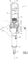
- the plunger 8 is preferably made of rubber and has some external ribs 8a for sliding within the internal volume V6 of the syringe barrel 6, in tight contact with an inner surface of this barrel.
- the plunger 8 has a central threaded opening 14 configured to be connected with a threaded distal end portion 16 of the plunger rod 10.
- the opening is not threaded before connection with the end portion 16.
- the needle 12 is fixedly mounted on the syringe barrel 6.
- the needle 12 is attached to the syringe barrel 6 by releasable means, such as a Luer-lock connection.
- S18 denotes a proximal end surface of the head 18 opposite to the end portion 16. This end surface S18 is configured to receive a pressure force exerted by the user, in order to push the plunger 8 toward the needle 12 and eject a liquid out of the syringe barrel 6, via the needle 12, when appropriate.
- the surface S18 may comprise a tactile structure with a distinctive shape which can be used for providing, for example, drug identification. Such a structure provides also better contact between the thumb and the surface S18 than a smooth surface.
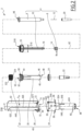
- the drug delivery device 2 also includes a needle cap 20, a needle cap remover 22 and a guiding member 24.
- the drug delivery device 2 also includes a sleeve 30, a compression spring 32, a cylindrical body 34 and a plunger rod cover 36.
- A40 denotes a longitudinal axis of this safety system 40.
- the sleeve 30 is mounted around the syringe barrel 6
- the body 34 is mounted around the sleeve 30 and the spring 32 is interposed, axially, between a portion of the sleeve 30 and a portion of the body 34, as explained here below.
- the sleeve 30 has a flange 44.
- the sleeve 30 is also provided with two pairs of external reliefs, namely a first pair of external reliefs 46 located next to a distal end 48 of the sleeve 30 and a second pair of external reliefs 50 located next to a proximal end 52 of the sleeve 30, opposite to the distal end 48.
- the flange 44 is located close to the second pair of external reliefs 50 and to the proximal end 52.
- the plunger rod cover 36 has a generally tubular shape.
- a wall 62 of the plunger rod cover 36 does not extend on a full circumference around the longitudinal axis A36 but is provided with a longitudinal slit or opening O36, which extends all the way along the longitudinal dimension of the plunger rod cover 36.
- the plunger rod cover 36 has the shape of a portion of a cylinder, open on one angular sector corresponding to the slit O36.
- a proximal end 622 of the wall 62 may be equipped with a closing wall, substantially perpendicular to the longitudinal axis A36 and preventing an axial action on the head 18, along the longitudinal axes A2 and A40.
- the plunger rod cover 36 also includes an outer peripheral collar 68 which surrounds a distal end 624 of the wall 62 and which is supposed to come into abutment against a proximal edge 70 of the body 34, when the parts 34 and 36 are coupled together.
- each through-hole 76 can be replaced by a blind hole with its opening oriented toward the longitudinal axis A36, thus toward the longitudinal axis A40 when parts 34 and 36 are coupled together.
- the body 34 is provided, close to its proximal end defined by the edge 70, with two deformable tabs 80, which protrude from an outer peripheral cylindrical surface S34 of the body 34, which is defined by the main portion 348.
- Each tab 80 is arc-shaped and is attached by its two ends 82 and 84 to the main portion 348 of the body 34, while it is separated from this main portion, between these two ends 82 and 84, by a gap G80.
- This gap allows each tab 80 to be flexible and to deform, preferably elastically, under a stress in a radial and inwardly oriented direction, with respect to the longitudinal axis A34.
- a radial and inwardly oriented direction can also be named a centripetal direction.
- each tab 80 is provided with a protrusion 86 which extends in a radial outwardly oriented direction with respect to the longitudinal axis A34, thus with respect to the longitudinal axis A40 when the body 34 is connected with the plunger rod cover 36.
- a radial and outwardly oriented direction can also be named a centrifugal direction.
- a protrusion 86 is located, along the circumference of the edge 70, between the two ends 82 and 84 and in the middle of the arc-shaped part of the tab connecting these ends of the corresponding tab 80.
- Two stops 88 are provided on the outer peripheral surface S34.
- the plunger rod cover 36 protects the plunger rod 10 and the head 18 from an unintended displacement along the longitudinal axis A2, from bending and from any other distortion.
- the safety system 40 is then in the configuration of figure 1 .
- each through hole 76 becomes radially aligned with the respective protrusion 86 and, due to the flexibility of the tabs 80, the protrusions 86 are pushed back in a radial outwardly oriented direction and move into the through holes 76, which forms recesses for accommodating the protrusions.
- each tab 80 equipped with a protrusion 86 forms a first coupling member arranged on the outer peripheral surface S64 of the body 34, whereas each axially extending structure 72 equipped with a through hole 76 forms a corresponding second coupling member arranged on the plunger rod cover 36.
- each through hole 76 forms a recess for accommodating, at least partially, one protrusion 86.
- the stops 88 form abutment surfaces for delimiting the end position of the disconnection process described here above. In this way the user is prevented from rotating the plunger rod cover 36 too far, which might result in connecting again the plunger rod cover with the body 34 after a rotation by 180°.
- the first and second coupling members 80 and 72 are in a coupled configuration, where the body 34 and the plunger rod cover 36 are coupled together along the longitudinal axis A40, by the cooperation of the collar 68 with the edge 70 and of the sliding surfaces S74 with the distal surfaces S'80.
- a disconnection process can be implemented by rotation of the plunger rod cover 36 with respect to the body 34 around the longitudinal axis A40, in a direction opposition to the direction used for coupling these two parts, namely the direction of arrow R D in figure 1 .
- rotation directions R C and R D may be reversed with respect to their directions shown in figure 1 .
- each tab 80 elastically deforms, so that its protrusion 86 is moved in a radial and inwardly oriented direction, with respect to the longitudinal axis A40, up to a point where each protrusion 86 is outside from the corresponding through hole 76.
- the protrusions 86 do not oppose a further rotational movement of the plunger rod cover in the direction of arrow R D , which allows decoupling parts 34 and 36 from each other.
- each tab 80 is configured to deform during the disconnection process.
- each tab 80 is flexible and configured to deform elastically during the disconnection process.
- the elastic deformation of the tabs 80 of the first embodiment during the disconnection process is possible due to the geometry of the body 34, in particular due to the geometry of the tabs 80 and to the presence of the gaps G80.
- the elastic properties of the tabs can be achieved with any material of the body 34 and/or the plunger rod cover 36 used in the manufacturing process, preferably manufacturing by injection molding.
- said material can be composed mainly of a copolymer of methyl methacrylate, acrylonitrile, butadiene and styrene (MABS), a copolymer of methyl methacrylate butadiene styrene (MMBS), polypropylene (PP), copolymer of acrylonitrile-butadiene-styrene (ABS), polyoxymethylene (POM), polyamide (PA), polybuthylene terephtalate (PBT), a polycarbonate (PC) or their mixtures.
- MABS copolymer of methyl methacrylate, acrylonitrile, butadiene and styrene
- MMBS methyl methacrylate butadiene styrene
- PP polypropylene
- ABS copolymer of acrylonitrile-butadiene-styrene
- POM polyoxymethylene
- PA polyamide
- PBT polybuthylene ter
- an angular amplitude of the rotational movement of the disconnection process is less than or equal to 100°, preferably between 30° and 50°. In the example of the figures, this angular amplitude is of about 40°, which is enough to make the ledges 74 of the axially extending structures 72 escape from the tabs 80 at the end of the disconnection process.
- the plunger rod cover 36 can be disengaged from the body 34 via an axial movement along the longitudinal axis A40, in the proximal direction.
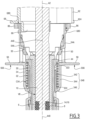
- the head 18 activates the connection between the sleeve 30 and the body 34. As shown in figure 6 , a peripheral surface S'18 of the head 18 engages the clips 54A. Due to this operation, the sleeve 30 is released and can be moved by the spring 32, in a proximal direction along the longitudinal axis A2. This moves the syringe barrel 6 and the needle 12 in the same direction in the proximal direction and the needle 12 becomes hidden within the body 34.
- EP2047879A1 One can make use here of the technical teachings of EP2047879A1 .
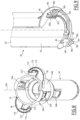
- Each tab 180 of the second embodiment is elastically deformable due to its geometry, in particular due to its U-shape.
- the chamfered surfaces 862 help the transition of the protrusions 186 from a configuration where they are engaged within the notches 176 to a configuration where they stay in the empty spaces E72, out of the notches.
- the second embodiment works in the same way as the first embodiment.
- the lateral extensions 72 and the tabs 80 are in a decoupled configuration and the plunger rod cover 36 can be moved in several directions, in particular translated along and rotated around the longitudinal axis A34 of the body 34.
- the extended finger flanges can be provided as a separate part, attachable to the body 34 and preferably attachable on a gripping surface of the main part 348 by any convenient means, e.g. by snapping or gluing.
- any convenient means e.g. by snapping or gluing.
- only one first coupling member can be provided on the body 34 and/or only one second coupling member can be provided on the plunger rod cover 36.
- three or more first coupling members can be provided on the body 34 and/or three or more second coupling members can be provided on the plunger rod cover 36.
- an elastically deformable tab with its two ends attached to a main part can be provided as second coupling member on the plunger rod cover 36 and a corresponding recess can be provided on the body 34.
- a deformable tab similar to the U shaped tab 80 of the second embodiment, can be provided on the body 34, whereas a corresponding notch is provided on the plunger rod cover 36.
- the protrusions 86 or 186 may extend in a radial inwardly oriented direction, with respect to the longitudinal axis A40 of the safety system 40.
- the location and geometry of the recesses are adapted accordingly.
- both coupling members provided on the body and on the plunger rod cover are flexible and elastically deform, at least during the disconnection process.
- At least one coupling member is deformed plastically only during the disconnection process.
Landscapes
- Health & Medical Sciences (AREA)
- Engineering & Computer Science (AREA)
- Hematology (AREA)
- Anesthesiology (AREA)
- Biomedical Technology (AREA)
- Heart & Thoracic Surgery (AREA)
- Vascular Medicine (AREA)
- Life Sciences & Earth Sciences (AREA)
- Animal Behavior & Ethology (AREA)
- General Health & Medical Sciences (AREA)
- Public Health (AREA)
- Veterinary Medicine (AREA)
- Environmental & Geological Engineering (AREA)
- Infusion, Injection, And Reservoir Apparatuses (AREA)
Priority Applications (1)
| Application Number | Priority Date | Filing Date | Title |
|---|---|---|---|
| EP23307366.7A EP4574189A1 (de) | 2023-12-22 | 2023-12-22 | Sicherheitssystem für eine spritze und arzneimittelabgabevorrichtung mit solch einem sicherheitssystem |
Applications Claiming Priority (1)
| Application Number | Priority Date | Filing Date | Title |
|---|---|---|---|
| EP23307366.7A EP4574189A1 (de) | 2023-12-22 | 2023-12-22 | Sicherheitssystem für eine spritze und arzneimittelabgabevorrichtung mit solch einem sicherheitssystem |
Publications (1)
| Publication Number | Publication Date |
|---|---|
| EP4574189A1 true EP4574189A1 (de) | 2025-06-25 |
Family
ID=89619476
Family Applications (1)
| Application Number | Title | Priority Date | Filing Date |
|---|---|---|---|
| EP23307366.7A Withdrawn EP4574189A1 (de) | 2023-12-22 | 2023-12-22 | Sicherheitssystem für eine spritze und arzneimittelabgabevorrichtung mit solch einem sicherheitssystem |
Country Status (1)
| Country | Link |
|---|---|
| EP (1) | EP4574189A1 (de) |
Citations (6)
| Publication number | Priority date | Publication date | Assignee | Title |
|---|---|---|---|---|
| CH676551A5 (en) * | 1989-07-13 | 1991-02-15 | Pedro Navarro | Single use medical syringe - has cap protecting plunger, fitted over injection needle to prevent harm during handling on disposal |
| US20040116874A1 (en) * | 2000-01-07 | 2004-06-17 | Armindo Lourenco | Device for injecting a dose of liquid in particular medicinal liquid |
| EP2047879A1 (de) | 2007-10-11 | 2009-04-15 | Rexam Pharma La Verpillière | Sicherheitseinrichtung für eine Spritzvorrichtung |
| WO2011135269A1 (fr) | 2010-04-28 | 2011-11-03 | Rexam Healthcare La Verpilliere | Dispositif de securite pour seringue d'injection pre-remplie |
| WO2019158547A1 (en) | 2018-02-16 | 2019-08-22 | Becton Dickinson France | Medical injection device for supporting a medical container filled with a pharmaceutical composition |
| US20210077745A1 (en) * | 2018-09-12 | 2021-03-18 | Promisemed Hangzhou Meditech Co.,Ltd. | Active Self-locking Type Syringe |
-
2023
- 2023-12-22 EP EP23307366.7A patent/EP4574189A1/de not_active Withdrawn
Patent Citations (6)
| Publication number | Priority date | Publication date | Assignee | Title |
|---|---|---|---|---|
| CH676551A5 (en) * | 1989-07-13 | 1991-02-15 | Pedro Navarro | Single use medical syringe - has cap protecting plunger, fitted over injection needle to prevent harm during handling on disposal |
| US20040116874A1 (en) * | 2000-01-07 | 2004-06-17 | Armindo Lourenco | Device for injecting a dose of liquid in particular medicinal liquid |
| EP2047879A1 (de) | 2007-10-11 | 2009-04-15 | Rexam Pharma La Verpillière | Sicherheitseinrichtung für eine Spritzvorrichtung |
| WO2011135269A1 (fr) | 2010-04-28 | 2011-11-03 | Rexam Healthcare La Verpilliere | Dispositif de securite pour seringue d'injection pre-remplie |
| WO2019158547A1 (en) | 2018-02-16 | 2019-08-22 | Becton Dickinson France | Medical injection device for supporting a medical container filled with a pharmaceutical composition |
| US20210077745A1 (en) * | 2018-09-12 | 2021-03-18 | Promisemed Hangzhou Meditech Co.,Ltd. | Active Self-locking Type Syringe |
Similar Documents
| Publication | Publication Date | Title |
|---|---|---|
| JP7783929B2 (ja) | 自動薬物送達装置 | |
| EP0409365B1 (de) | Einrichtung zur Eigeninjektion mit Sicherheitskappe | |
| RU2607939C2 (ru) | Автоматический инъектор | |
| US7387615B2 (en) | Single use syringe having safety shield | |
| JP5619037B2 (ja) | 後退可能な針を備えたシリンジ用のシール部材 | |
| CN103957971B (zh) | 针安全装置 | |
| EP2131902B1 (de) | Spritzenanordnung mit deaktivierungsmechanismus mit manipulationssicherer funktion | |
| RU2603289C2 (ru) | Устройство подачи лекарства для введения заданной дозы медикамента | |
| US6889830B2 (en) | Device for separating the connecting end of a hypodermic needle from the tip of an injection instrument | |
| US20100076378A1 (en) | Safety Medical Syringe with Retractable Needle and Including a Plunger that is Received within a Barrel | |
| WO2016169756A1 (en) | Drive mechanism for an autoinjector | |
| JP2013526356A (ja) | 薬物送達デバイス用ニードルアセンブリ | |
| KR200493963Y1 (ko) | 플런저 반발압력 저감 구조를 갖는 주사기 | |
| KR102250909B1 (ko) | 펜 타입 주사기용 원클릭 펜니들 | |
| US12433999B2 (en) | Injection device incorporating a needle shield remover | |
| US12599721B2 (en) | Cartridge fixation for a drug delivery device | |
| CN113975539B (zh) | 注射头组件、注射器主体和注射器 | |
| CN114502217B (zh) | 安全注射装置 | |
| EP3603705B1 (de) | Spritze | |
| CN113975540B (zh) | 注射头组件、注射器主体和注射器 | |
| EP4346960B1 (de) | Module für eine medikamentenverabreichungskomponente | |
| US20250152836A1 (en) | A sub-assembly for a medicament delivery device | |
| JP2025536792A (ja) | 薬物送達デバイスに取り付けるための安全デバイス | |
| EP2716324A1 (de) | Mikronadelanordnung und Adapter | |
| WO2024008491A1 (en) | A sub-assembly of a medicament delivery device |
Legal Events
| Date | Code | Title | Description |
|---|---|---|---|
| PUAI | Public reference made under article 153(3) epc to a published international application that has entered the european phase |
Free format text: ORIGINAL CODE: 0009012 |
|
| STAA | Information on the status of an ep patent application or granted ep patent |
Free format text: STATUS: THE APPLICATION HAS BEEN PUBLISHED |
|
| AK | Designated contracting states |
Kind code of ref document: A1 Designated state(s): AL AT BE BG CH CY CZ DE DK EE ES FI FR GB GR HR HU IE IS IT LI LT LU LV MC ME MK MT NL NO PL PT RO RS SE SI SK SM TR |
|
| STAA | Information on the status of an ep patent application or granted ep patent |
Free format text: STATUS: THE APPLICATION IS DEEMED TO BE WITHDRAWN |
|
| 18D | Application deemed to be withdrawn |
Effective date: 20260103 |