EP4574206A1 - Procédé de détection de cavitation - Google Patents
Procédé de détection de cavitation Download PDFInfo
- Publication number
- EP4574206A1 EP4574206A1 EP23307374.1A EP23307374A EP4574206A1 EP 4574206 A1 EP4574206 A1 EP 4574206A1 EP 23307374 A EP23307374 A EP 23307374A EP 4574206 A1 EP4574206 A1 EP 4574206A1
- Authority
- EP
- European Patent Office
- Prior art keywords
- cavitation
- signal
- target
- matrix
- transducer
- Prior art date
- Legal status (The legal status is an assumption and is not a legal conclusion. Google has not performed a legal analysis and makes no representation as to the accuracy of the status listed.)
- Pending
Links
Images



Classifications
-
- A—HUMAN NECESSITIES
- A61—MEDICAL OR VETERINARY SCIENCE; HYGIENE
- A61N—ELECTROTHERAPY; MAGNETOTHERAPY; RADIATION THERAPY; ULTRASOUND THERAPY
- A61N7/00—Ultrasound therapy
- A61N7/02—Localised ultrasound hyperthermia
-
- A—HUMAN NECESSITIES
- A61—MEDICAL OR VETERINARY SCIENCE; HYGIENE
- A61B—DIAGNOSIS; SURGERY; IDENTIFICATION
- A61B8/00—Diagnosis using ultrasonic, sonic or infrasonic waves
- A61B8/52—Devices using data or image processing specially adapted for diagnosis using ultrasonic, sonic or infrasonic waves
- A61B8/5215—Devices using data or image processing specially adapted for diagnosis using ultrasonic, sonic or infrasonic waves involving processing of medical diagnostic data
- A61B8/5223—Devices using data or image processing specially adapted for diagnosis using ultrasonic, sonic or infrasonic waves involving processing of medical diagnostic data for extracting a diagnostic or physiological parameter from medical diagnostic data
-
- A—HUMAN NECESSITIES
- A61—MEDICAL OR VETERINARY SCIENCE; HYGIENE
- A61B—DIAGNOSIS; SURGERY; IDENTIFICATION
- A61B8/00—Diagnosis using ultrasonic, sonic or infrasonic waves
- A61B8/52—Devices using data or image processing specially adapted for diagnosis using ultrasonic, sonic or infrasonic waves
- A61B8/5269—Devices using data or image processing specially adapted for diagnosis using ultrasonic, sonic or infrasonic waves involving detection or reduction of artifacts
-
- A—HUMAN NECESSITIES
- A61—MEDICAL OR VETERINARY SCIENCE; HYGIENE
- A61N—ELECTROTHERAPY; MAGNETOTHERAPY; RADIATION THERAPY; ULTRASOUND THERAPY
- A61N7/00—Ultrasound therapy
- A61N2007/0039—Ultrasound therapy using microbubbles
-
- A—HUMAN NECESSITIES
- A61—MEDICAL OR VETERINARY SCIENCE; HYGIENE
- A61N—ELECTROTHERAPY; MAGNETOTHERAPY; RADIATION THERAPY; ULTRASOUND THERAPY
- A61N7/00—Ultrasound therapy
- A61N2007/0043—Ultrasound therapy intra-cavitary
-
- A—HUMAN NECESSITIES
- A61—MEDICAL OR VETERINARY SCIENCE; HYGIENE
- A61N—ELECTROTHERAPY; MAGNETOTHERAPY; RADIATION THERAPY; ULTRASOUND THERAPY
- A61N7/00—Ultrasound therapy
- A61N2007/0078—Ultrasound therapy with multiple treatment transducers
-
- A—HUMAN NECESSITIES
- A61—MEDICAL OR VETERINARY SCIENCE; HYGIENE
- A61N—ELECTROTHERAPY; MAGNETOTHERAPY; RADIATION THERAPY; ULTRASOUND THERAPY
- A61N7/00—Ultrasound therapy
- A61N7/02—Localised ultrasound hyperthermia
- A61N7/022—Localised ultrasound hyperthermia intracavitary
Definitions
- the invention relates to a method for detecting cavitation, more particularly a method for detecting cavitation emitted by an ultrasound apparatus.
- Acoustic cavitation is used in multiple biomedical applications to generate a mechanical (and sometimes thermal) effect in tissues. Since it has an important impact on the tissues, it is crucial to well monitor its presence and position in the patient body. Because the cavitation cloud nucleated by focused ultrasound is hyperechoic, B-mode imaging is used in several applications to observe cavitation during therapy. However, for clinical application, the quality of B-mode imaging might be greatly affected by the presence of soft tissues between the imaging probe and the cavitation cloud. Hence, it is important to incorporate a cavitation detection system to cavitation-based ultrasound therapeutic medical devices.
- PCD Passive cavitation detection
- PCI passive cavitation imaging
- S. I. Madanshetty, R. A. Roy, et R. E. Apfel, J. Acoust. Soc. Am., vol. 90, no 3, p. 1515-1526, sept. 1991 are widely used methods to detect cavitation. They consist in having a transducer different than the therapeutic transducer (or a hydrophone) "listening" to the echoes of the signal emitted by the therapeutic transducer. A backscattered signal is acquired and inertial cavitation is known to have a typical broadband spectral signature.
- inertial cavitation dose the root-mean-square amplitude of the broadband noise in the frequency domain
- the probability of cavitation occurrence the cavitation persistence.
- broadband noise is the most used method for the analysis of PCD and PCI signal.
- cavitation imaging and analysis can be enhanced with the use of ultrafast ultrasound imaging since it increases the frame of acquisition, and allows a better discrimination of the signals.
- ACD active cavitation detection
- Self-sensing transducers have also been used for aberration correction in ultrasonic imaging application and for histotripsy applications. In these solutions, the same element is used to emit and receive signal. It is known from document J. R. Sukovich et al., IEEE Trans. Ultrason. Ferroelectr. Freq. Control, vol. 67, no 6, p. 1178-1191, June 2020 to use signal which is first acquired through the skull by using a pressure level configure to not nucleate cavitation in order to obtain the echoes caused by the skull; then the cavitation signal is acquired and the signal without cavitation is subtracted. Finally, the cavitation localization is determined with an algorithm.
- the invention intends to obviate at least partly the drawbacks of the prior art.
- the invention aims to provide a method and a device to automatically detect cavitation while simplifying the instrumental detection, avoiding the alignment difficulties between two ultrasonic devices, enhancing signal detection and usable under tissue motion.
- the invention relates to a computer-implemented method for identifying cavitation produced by an ultrasound therapy device, the ultrasound therapy device comprising at least one transducer configured for emitting ultrasound waves in a target and for receiving backscattered signal from the target, the method comprising the following steps of:
- the method of the invention is not carried out on a single measure received from the target but uses a series of measurements allowing a better determination of the variability of the high energy values through the series.
- the inventors found out that the backscattered signal from the emitting signal show stable/constant amplitude and positions through the different measurements signals while the cavitation, because of its erratic apparitions, shows variable and unstable amplitudes through a range of positions on the different measurements signals. This allows detecting sample values in the series of measurement corresponding to cavitation.
- the method of the invention can be advantageously carried out on a moving target, especially on a target with a pattern movement, like the heart of a patient, and on target impacted by breathing movement like the liver of a patient.
- the ultrasound device configured for nucleating cavitation in the target may emit focused waves at a focal zone of the target or may emit diverging waves.
- Step a) corresponds to the arrangement in a raw matrix of a series of sampled acquired measurements signals from the target.
- the raw matrix corresponds then to a two dimensional temporal representation of the series of measurements, wherein one of the dimensions represents the recording time of each backscattered signal and the other dimension represents the start time of each measurements signal.
- Each signal can be shorter than the time between two pulses of emitting signal.
- Each sampled acquired measurement signal comprises at least 20 samples, notably at least 40 samples.
- Each acquired measurement signal are sampled and stored in a matrix.
- the whole sampled signals may be stored along the rows or along the columns of the matrix.
- each sample corresponds to a particular amplitude value of the signal obtained at a time of sampling.
- the sampling frequency may be from 5 to 15 times the at least one transducer frequency, for example from 3MHz to 15MHz.
- each row, or each column contains the samples of each sampled signal of the same time of recording after the beginning of the emitting signal.
- sampled signals of the series do not comprise the same amount of samples, they may be modified to match the exact same amount of samples. To that end, they may be aligned by matching the time of record of their samples and the sampled values which do not have a time of record shared by all sampled signal may be adapted. In particular, according to a first adaptation the sample values of the sampled signals beyond (before or after) those of the shortest sampled signal may be cut. Alternatively, according to a second adaptation, the sampled signals shorten than the longest sampled signal may be completed with corresponding sampled values equal to 0.
- Step b) of the invention allows determining the presence or absence of one or more samples corresponding to cavitation in the raw matrix.
- Each sampled signal can be segmented into different time windows, each corresponding to at least one sample, namely an emission window, at least one echo window and possibly a cavitation window.
- the time windows are considered along the columns of the raw matrix when the sampled signals are aligned along the rows and vice-versa.
- the emission window corresponds to amplitude values emitted by the emitting signal. Indeed, because the signal is acquired with the same transducer that also emits the emitting signal, the beginning of an acquired signal does not correspond to backscattered signal but directly to amplitude values of the emitting signal.
- the emission window then lasts for the duration of the pulse of the emitting signal. Because the duration of the pulse is known, the samples within the emission window may be directly forced to be zero in this step. Otherwise, the samples within the emission window may be filtered, as described in details below.
- An echo window comprises samples corresponding to amplitude values emitted solely by the echoes of the emitting signal from the target.
- the echo window does not comprise cavitation, but a cavitation window may comprise echoes of the emitting signal, as described below.
- the echo window does not overlap the emission window.
- the echo windows comprise samples which values are considered stable and repeatable through the different acquired signal measurements, notably the value of the samples may differ from 20 to 75% through the different sampled signals of the echo windows. Such a difference is greatly less than the difference of the values of the samples in the cavitation windows, which ranges between 200% and 600%.
- the echo windows comprise high sample values, notably sample values between 15% and 200% of the cavitation maximal amplitude expected possible range.
- the echo window position in each acquired sampled signal may be determined in a preliminary step on a series of measures acquired in the same operation conditions, and applied to the series of measure of step a).
- the echo window may be determined on the raw matrix or on a filtered matrix obtained at substep i) of step b) and described in details below as a time window between the emission window and the time of a determined beginning of focalisation at the focal zone of the emitting signal.
- the echo window may be determined on a filtered matrix obtained at substep i) of step b) and described in details below, as a time window after the emission window and outside of a zone beginning two times the emitting signal duration before the maximum sample value of each sampled signal and ending two times the emitting signal duration after the said maximal value.
- the maximum sample value of each sampled signal is assumed to correspond to cavitation. Because the signal of cavitation can be considered shorter than four times the emitting duration, each sample value which is outside of a time window of four times the emitting duration around cavitation can be considered to be in an echo window.
- a sample signal may comprise a cavitation window comprising sample values generated by cavitation at the focal zone of the target.
- the purpose of step b) is to identify the presence of such sample values.
- the cavitation window varies more in position and amplitude values through the different sampled signals.
- the cavitation window may also comprise sample values pertaining to the echoes of the emitting signal, which will be differentiated from the sample(s) corresponding to cavitation, as described in details below.
- Step b) may be at least partially carried out by an artificial intelligence engine.
- the artificial intelligence engine can be based on any model of artificial intelligence (Al).
- Artificial intelligence models for example AI based classifiers may be used, machine learning models may be used, e.g. deep learning-based models, neural networks, logistic regression models, random forest models, support vector machine models or tree-based models with decision trees as a basis may be used.
- the AI is especially a convolution neural network pertaining to the deep learning-based models.
- the artificial intelligence engine carries out the entire step b).
- the artificial intelligence engine may be trained with a pool of series of measurements each arranged according to the raw matrix of step a), and each associated with an annotation of the presence or absence of cavitation in the series.
- the artificial intelligence engine has a data structure containing information reflecting relationship between sample values of the raw matrix and the presence of cavitation. Hence, from the raw matrix provided at step a), the artificial intelligence engine returns the determination of presence or absence of sample(s) corresponding to cavitation in the series of sampled signals.
- step b) can be carried out by:
- sample values corresponding to the emitting signal are also filtered in case they were not previously put to 0.
- One or both of these sub-steps may be carried out by an artificial intelligence engine.
- the artificial intelligence engine may be trained on a pool of raw matrix according to step a) associated with an annotation of the position of the echoes of the emitting signal, and optionally of the emitting signal itself.
- the artificial intelligence engine has a data structure containing information reflecting relationship between sample values of the raw matrix and the presence of echoes from the emitting signal and optionally of the emitting signal itself.
- the artificial intelligence engine returns a filtered matrix where the samples corresponding to the echoes of the emitting signal and optionally of the emitting signal itself are treated.
- the treatment may be a lowering of values, a transformation to 0 or a removing of the sample(s) corresponding to the echo window(s) along the series.
- Substep i) of step b) may also be carried out by applying a 2D temporal filter to the raw matrix for obtaining a filtered matrix.
- the 2D temporal filter applied to the raw matrix may be configured for distinguishing samples corresponding to stable values to other along the series.
- the filter applied to the matrix may be configured to separate the stable samples with a high coherence in the 2D temporal dimensions of the raw matrix from the unstable samples with a low 2D temporal coherence.
- the 2D temporal filter applied to the matrix carries out a singular value decomposition filtering of the matrix.
- the singular values are ranked from the highest to the lowest value.
- the obtained first singular values correspond to the most coherent signal, i.e. to echoes (and pulses if not previously filtered).
- the last singular values correspond to noise.
- the in-between singular values may correspond to cavitation.
- the first and last singular values are removed and the remaining intermediate values are kept for the continuation.
- the first of the intermediate singular values may correspond to the 2 nd to the 15 th singular value, while the last of the intermediate singular values may corresponds to at least the 20 th value.
- the singular value decomposition filtering applied during substep i) of step b) may be followed by a high-pass filter, to attenuate the coherent signals corresponding to echoes remaining after the singular values decomposition filtering.
- the cut-off value of the high-pass filter may be the emitting signal pulse-repetition frequency divided by 3 to 5 (typically between 20Hz and 160Hz) and the attenuation slope may be from -20dB/decades to -40dB/decades.
- substep ii) may be carried out by an artificial intelligence engine.
- This artificial intelligence engine may be trained on a pool of filtered matrix associated with an annotation of the presence or absence of cavitation.
- the artificial intelligence engine has a data structure containing information reflecting relationship between amplitudes values of the filtered matrix and the presence of cavitation. Hence, from the filtered matrix, the artificial intelligence engine returns the determination of presence or absence of cavitation in the series of measures.
- Substep ii) may also be carried out by using one more indicators.
- a signal-to-noise ratio indicator may be determined for each filtered sample signal as the maximal value of the filtered samples divided by the standard deviation of the filtered sample values in one echo window. If the result is higher than a predetermined threshold, the raw matrix is considered as presenting cavitation.
- an energy indicator may be determined for each filtered sampled signal as the square root of the integral of the filtered samples values. Again, if the result is higher than a predetermined threshold, the filtered sampled signal, and thus the corresponding sample signal, is considered as presenting cavitation.
- the method of the invention may comprise a preliminary acquisition step of carrying out a series of measures, each measure comprising acquiring the echoes received from the target by the at least one transducer as a measurement signal.
- all steps from the preliminary acquisition step to step b) or solely step a) and b) are performed by a computer.
- the emitting signal may be a sinusoidal signal at a frequency ranging from 100kHz to 10MHz, and even more preferably from 500kHz to 2.5MHz, with high intensity pulsed emission form 1 to 20 ⁇ s, delivered at a pulse repetition frequency ranging from 1Hz to 1000Hz, and even more preferably from 50Hz to 500Hz.
- Each acquired signal is then sampled before step a).
- the method may also comprise a step c) of repeating acquisition preliminary step to step b).
- This aspect of the invention allows monitoring the presence of cavitation in the focus zone along the therapy treatment.
- the invention also relates to a computer system configured to be in communication with an ultrasound therapy device, the ultrasound therapy device comprising: at least one transducer configured for emitting ultrasound waves at a target and for receiving backscattered signal from a target, the computer system comprising one or more processors, a memory and one or more programs, wherein the one or more programs are stored in the memory and configured to be executed by the one or more processors, the one or more programs including instructions for performing, when executed by the computer system, a method for identifying cavitation as above defined.
- the at least one transducer are also configured for emitting ultrasound waves at a target.
- the ultrasound therapy device may comprise a communication member to send the backscattered signal from the target to the computer system and receive order from the computer system.
- the computer system comprising may also comprise a communication member to receive information from the ultrasound therapy device and to send orders to the ultrasound therapy device.
- the one or more programs include instructions for performing a preliminary acquisition step upstream step a) of carrying out a series of measures, each measure comprising the following sub-steps:
- the therapy device of the invention uses the same at least one transducer to carry out both
- This aspect of the invention avoids double focus problems, and reduces the volume of the therapy device.
- the therapy device comprises several transducers, it is possible to use solely one of them, or several or all of them, to record the different backscattered signal of the series of measurements.
- the therapy device may comprise a signal generator followed by a high power amplifier linked to the at least one transducer.
- the transducers that can be used to emit the emitting signal can be of any type.
- the at least one transducer may be an array of concentric annular ultrasound transducer as described in detail in WO2016156989 .
- the invention also relates to a computer program product, stored on a non-transitory computer-readable data-storage medium comprising computer-executable instructions to cause a computer system to carry out a method for identifying cavitation as above defined.
- the invention finally relates to a non-transitory computer-readable data-storage medium containing computer-executable instructions to cause a computer system to carry out a method for identifying cavitation as above defined.
- the invention also relates to an apparatus comprising the computer system as above defined and an ultrasound therapy device configured for detection of cavitation, the ultrasound therapy device comprising: at least one transducer configured for emitting ultrasound waves at a target and for receiving backscattered signal from the target.
- the at least one transducer are also configured for emitting ultrasound waves at a target.
- the apparatus may comprise a high-voltage probe linked the at least one transducer and followed by an oscilloscope.
- the high-voltage probe allows respecting the amplitude range of the oscilloscope.
- the apparatus (10) of the invention comprises a computer system (11) and an ultrasound therapy device (12).
- the ultrasound therapy device (12) comprises at least one transducer (120) configured for on one hand emitting ultrasound waves (20) at a target (30) via its surface (32) adapted for nucleating cavitation within the target (30) and for on another hand receiving a backscattered signal (40) from the target (30).
- the at least one transducer (120) are configured for emitting focused ultrasound waves (20) at a focal zone (31) of a target (30) as represented.
- the ultrasound therapy device (12) comprises an array of transducers (120) for emitting ultrasound waves (20) and at least one of the said transducers (120) is configured for receiving the backscattered signal (40).
- the therapy device (12) may comprise a signal generator (121) followed by a high power amplifier (122) linked to the at least one transducer (120).
- the ultrasound therapy device (12) may further comprise a communication member (not shown) to send information to the computer system (11) and notably the different signals of the backscattered signal (40) acquired by the at least one transducer (120), and to receive order(s) from the computer system (11).
- the communication member may be wireless or wired.
- the apparatus (10) may comprise, between the ultrasound therapy device (12) and the computer system (11), a high-voltage probe (13) linked to the at least one transducer (120) and followed by an oscilloscope (14).
- the high-voltage probe (13) allows respecting the amplitude range of the oscilloscope (14).
- the oscilloscope transmits the signals to the computer system (11), where the signals are stored and sampled.
- Such an oscilloscope (14) allows monitoring the well reception of the echoes signals and their aspect.
- the computer system (11) comprises one or more processors, a memory notably for storing the echoes signals and one or more programs, and notably a communication member to receive information from the ultrasound therapy device (12) and send order to the latter.
- the communication member may be wireless or wired.
- the one or more programs are configured to be executed by the one or more processors.
- the one or more programs comprise instructions for performing, when executed by the computer system (11), a method for identifying cavitation from the echoes signal (40).
- the one or more programs may further comprise instructions to be executed by the ultrasound therapy device (12).
- the one or more programs may further comprise instructions to pilot series of emitting signal by the ultrasound therapy device (12).
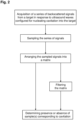
- Figure 2 represents an organigram of the computer-implemented method for identifying cavitation produced by an ultrasound therapy device (12).
- the first and optional represented step corresponds to the acquisition of a series of echoes signals in response to ultrasound waves emitted by the ultrasound therapy device (12). Then the series is sampled and arranged in a matrix along the rows or the columns. From the matrix, the presence or absence of one or more samples corresponding to cavitation can be directly determined (notably via an intelligence engine), or the matrix may be filtered before to highlight difference between sample(s) corresponding to echoes of the emitting signal and sample(s) corresponding to the cavitation.
- a returned signal from the phantom tissue was acquired at 12.5MHz between each pulse by one of the elements of the therapy transducer connected to an oscilloscope (MDO4054B-6, Tektronix ® , USA) and a computer on which is installed the software Matlab ® (Mathworks ® ) for the acquisitions, filtering and indicators calculation and a Python ® integrated development environment with Tensorflow ® and Keras ® libraries for AI applications.
- Matlab ® Matlab ®
- Acquisitions lasted 0.4s each which corresponds to a series of 40 acquisitions at a pulse-repetition frequency of 100Hz.
- the inventors first assayed the detection of cavitation on the fixed phantom tissue.
- Example 2 Pulses' echoes removing on a moving object
- the inventors then assayed removing the pulse's echoes on the moving phantom tissue.
- the power of the therapy transducer was here reduced to 570W to not nucleate cavitation below the moving phantom tissue in the water environment.
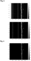
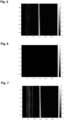
- the different acquired signals were sampled and arranged in a matrix represented in Figure 5 .
- the first high amplitude values corresponding to the pulse were put to 0 and the signal after 300 ⁇ s was removed from the matrix.
- the echoes are different from one acquired signal to another.
- the power of the therapy transducer was here increased to 1847W to nucleate cavitation below the moving phantom tissue.
- the different acquired signals were sampled and arranged in a matrix represented in Figure 8 .
- the first high amplitude values corresponding to the pulse were put to 0 and the signal after 300 ⁇ s was removed from the matrix.
- the echoes (around 50 and 150 ⁇ s) are different from one acquired signal to another.
- Cavitation signal is after 200 ⁇ s and as observed in Figure 3 , the amplitude and position of the echoes from the emitted signal are repeatable through the different pulses, while the amplitude and position of the cavitation vary from one pulse to another.
- the inventors then assayed on different targets: water, fixed phantom tissue and moving phantom tissue to automatically identify cavitation.
- Example 1 The conditions of Example 1 were repeated on the different targets, in cavitation and no cavitation conditions.
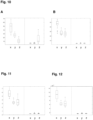
- the obtained matrices were filtered in a first case thanks to singular value decomposition wherein singular values between the 4 th and 30 th were kept for the continuation and further filtered in a high-pass filter with a cut-off value of 20Hz and an attenuation slope of - 20dB/decades, and in a second comparative case with the comparative filter described in Example 2.
- SNR signal-to-noise ratio
- the value of the SNR of each acquired signal in the different conditions is represented on Figure 10 as box plots (A: comparative; B: invention).
- A comparative
- B invention
- the comparative filter does not allow differentiating cavitation and no cavitation conditions on water and moving phantom targets, while with singular value decomposition high amplitudes from cavitation are significantly detected.
- Threshold for cavitation with the used transducer can be easily determined from those representations using the method of the invention.
- the inventors then assayed to determine the presence and absence of cavitation using artificial intelligences.
- CNN Conventional neural networks (CNN) developed in python with Tensorflow ® and Keras ® libraries were trained with a pool of series of measurements each arranged according to the raw matrix of step a) of the method of the invention, each series being associated with an annotation of the presence or absence of cavitation.
- CNN a One of the conventional neural networks (CNN a ) was then selected as the most relevant CNN on testing series of measurements.
- CNN b One of the conventional neural networks (CNN b ) was then selected as the most relevant CNN on testing series of measurements.
- the power of the therapy transducer was here reduced to 934W to not nucleate cavitation below the moving phantom tissue.
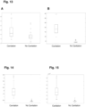
- Example 2 the conditions of Example 2 were used to determine the signal-to-noise ratio (SNR) of the acquisitions represented on Figures 16B and 17B , used as positive control.
- SNR signal-to-noise ratio
- this experiment supports the efficiency of the SVD filter combined with SNR, and demonstrates the efficiency of the convolution neural network with a raw matrix as input and the efficiency of the convolution neural network with a filtered matrix as input for the identification of cavitation.
Landscapes
- Health & Medical Sciences (AREA)
- Life Sciences & Earth Sciences (AREA)
- Engineering & Computer Science (AREA)
- Animal Behavior & Ethology (AREA)
- Veterinary Medicine (AREA)
- Public Health (AREA)
- Nuclear Medicine, Radiotherapy & Molecular Imaging (AREA)
- General Health & Medical Sciences (AREA)
- Radiology & Medical Imaging (AREA)
- Biomedical Technology (AREA)
- Biophysics (AREA)
- Medical Informatics (AREA)
- Molecular Biology (AREA)
- Surgery (AREA)
- Heart & Thoracic Surgery (AREA)
- Pathology (AREA)
- Physics & Mathematics (AREA)
- Computer Vision & Pattern Recognition (AREA)
- Physiology (AREA)
- Surgical Instruments (AREA)
Priority Applications (2)
| Application Number | Priority Date | Filing Date | Title |
|---|---|---|---|
| EP23307374.1A EP4574206A1 (fr) | 2023-12-22 | 2023-12-22 | Procédé de détection de cavitation |
| PCT/EP2024/087834 WO2025133076A1 (fr) | 2023-12-22 | 2024-12-20 | Procédé mis en œuvre par ordinateur pour détecter une cavitation |
Applications Claiming Priority (1)
| Application Number | Priority Date | Filing Date | Title |
|---|---|---|---|
| EP23307374.1A EP4574206A1 (fr) | 2023-12-22 | 2023-12-22 | Procédé de détection de cavitation |
Publications (1)
| Publication Number | Publication Date |
|---|---|
| EP4574206A1 true EP4574206A1 (fr) | 2025-06-25 |
Family
ID=89620167
Family Applications (1)
| Application Number | Title | Priority Date | Filing Date |
|---|---|---|---|
| EP23307374.1A Pending EP4574206A1 (fr) | 2023-12-22 | 2023-12-22 | Procédé de détection de cavitation |
Country Status (2)
| Country | Link |
|---|---|
| EP (1) | EP4574206A1 (fr) |
| WO (1) | WO2025133076A1 (fr) |
Citations (5)
| Publication number | Priority date | Publication date | Assignee | Title |
|---|---|---|---|---|
| WO2016156989A1 (fr) | 2015-04-02 | 2016-10-06 | Cardiawave | Procédé et appareil pour le traitement d'une valvulopathie |
| WO2018138576A1 (fr) * | 2017-01-25 | 2018-08-02 | Insightec, Ltd. | Localisation par cavitation |
| US20190269385A1 (en) * | 2010-06-09 | 2019-09-05 | Regents Of The University Of Minnesota | Dual mode ultrasound transducer (dmut) system and method for controlling delivery of ultrasound therapy |
| WO2019234497A1 (fr) * | 2018-06-06 | 2019-12-12 | Insightec, Ltd. | Système à ultrasons focalisés avec surveillance optimisée de la cavitation |
| EP3801761B1 (fr) * | 2018-05-25 | 2022-07-06 | Cardiawave SA | Appareil de traitement par ultrasons comportant des moyens d'imagerie des bulles de cavitation |
-
2023
- 2023-12-22 EP EP23307374.1A patent/EP4574206A1/fr active Pending
-
2024
- 2024-12-20 WO PCT/EP2024/087834 patent/WO2025133076A1/fr active Pending
Patent Citations (5)
| Publication number | Priority date | Publication date | Assignee | Title |
|---|---|---|---|---|
| US20190269385A1 (en) * | 2010-06-09 | 2019-09-05 | Regents Of The University Of Minnesota | Dual mode ultrasound transducer (dmut) system and method for controlling delivery of ultrasound therapy |
| WO2016156989A1 (fr) | 2015-04-02 | 2016-10-06 | Cardiawave | Procédé et appareil pour le traitement d'une valvulopathie |
| WO2018138576A1 (fr) * | 2017-01-25 | 2018-08-02 | Insightec, Ltd. | Localisation par cavitation |
| EP3801761B1 (fr) * | 2018-05-25 | 2022-07-06 | Cardiawave SA | Appareil de traitement par ultrasons comportant des moyens d'imagerie des bulles de cavitation |
| WO2019234497A1 (fr) * | 2018-06-06 | 2019-12-12 | Insightec, Ltd. | Système à ultrasons focalisés avec surveillance optimisée de la cavitation |
Non-Patent Citations (5)
| Title |
|---|
| J. R. SUKOVICH ET AL., IEEE TRANS. ULTRASON. FERROELECTR. FREQ. CONTROL, vol. 67, no. 6, June 2020 (2020-06-01), pages 1178 - 1191 |
| K.-A. SAALBACHJ. TWIEFELJ. WALLASCHEK, ULTRASONICS, vol. 94, April 2019 (2019-04-01), pages 401 - 410 |
| R. A. ROYS. I. MADANSHETTYR. E. APFEL, J. ACOUST. SOC. AM., vol. 87, no. 6, June 1990 (1990-06-01), pages 2451 - 2458 |
| S. I. MADANSHETTYR. A. ROYR. E. APFEL, J. ACOUST. SOC. AM., vol. 90, no. 3, September 1991 (1991-09-01), pages 1515 - 1526 |
| SUAREZ ESCUDERO DANIEL ET AL: "2D and 3D real-time passive cavitation imaging of pulsed cavitation ultrasound therapy in moving tissues", PHYSICS IN MEDICINE & BIOLOGY, vol. 63, no. 23, 6 December 2018 (2018-12-06), pages 235028, XP055844319, Retrieved from the Internet <URL:http://iopscience.iop.org/article/10.1088/1361-6560/aaef68> [retrieved on 20240513], DOI: 10.1088/1361-6560/aaef68 * |
Also Published As
| Publication number | Publication date |
|---|---|
| WO2025133076A1 (fr) | 2025-06-26 |
Similar Documents
| Publication | Publication Date | Title |
|---|---|---|
| US12285294B2 (en) | Shear wave elastrography method and apparatus for imaging an anisotropic medium | |
| US11020006B2 (en) | Transcranial photoacoustic/thermoacoustic tomography brain imaging informed by adjunct image data | |
| EP0500801B1 (fr) | Procede et appareil de mesure et de mise en images de la compressibilite ou elasticite de tissus | |
| US6951542B2 (en) | Method and apparatus for ultrasound imaging of a biopsy needle or the like during an ultrasound imaging examination | |
| CN1954235B (zh) | 用于超声波信号的局部频谱分析的改进方法和设备 | |
| CN108652672B (zh) | 一种超声成像系统、方法及装置 | |
| CN112218586B (zh) | 用于超声筛查的系统和方法 | |
| CN110361357B (zh) | 一种用于皮肤检测的单阵元光声谱信号获取系统及方法 | |
| KR20190088165A (ko) | 초음파 영상장치 및 그 제어방법 | |
| CN107049237A (zh) | 信息获取装置和信号处理方法 | |
| CN109363644B (zh) | 一种基于同轴时域分辨光声成像的检测系统 | |
| US10588606B2 (en) | Ultrasound coupling medium detection | |
| KR20140086626A (ko) | 전단파의 변위 산출 방법, 전단파를 이용한 피검체의 기계적 계수 산출 방법 및 이를 포함하는 시스템 | |
| JP7112713B2 (ja) | 心拍計測処理装置 | |
| EP4574206A1 (fr) | Procédé de détection de cavitation | |
| Jeong et al. | A novel approach for the detection of every significant collapsing bubble in passive cavitation imaging | |
| EP4081293B1 (fr) | Dispositif de surveillance des traitements hifu | |
| EP1964518A1 (fr) | Appareil ultrasonore médical ayant une fonction de confirmation de position d'irradiation | |
| KR20230100687A (ko) | 프로브 및 이를 이용한 트랜스듀서의 열화 예방 방법 | |
| JP2012110416A (ja) | 測定装置 | |
| Garay et al. | Passive and active cavitation detection methods: inception and persistence during HIFU sonication | |
| Mast et al. | Analytic and numerical modeling of ultrasonic B-scan and echo decorrelation imaging | |
| WO2023022133A1 (fr) | Procédé de traitement d'informations physiologiques, appareil et programme de traitement d'informations physiologiques | |
| US20250037843A1 (en) | Systems and methods for measuring fractal dynamics of density rate variability in breast cancer | |
| JP2008080101A (ja) | 光トモグラフィ装置 |
Legal Events
| Date | Code | Title | Description |
|---|---|---|---|
| PUAI | Public reference made under article 153(3) epc to a published international application that has entered the european phase |
Free format text: ORIGINAL CODE: 0009012 |
|
| STAA | Information on the status of an ep patent application or granted ep patent |
Free format text: STATUS: THE APPLICATION HAS BEEN PUBLISHED |
|
| AK | Designated contracting states |
Kind code of ref document: A1 Designated state(s): AL AT BE BG CH CY CZ DE DK EE ES FI FR GB GR HR HU IE IS IT LI LT LU LV MC ME MK MT NL NO PL PT RO RS SE SI SK SM TR |
|
| STAA | Information on the status of an ep patent application or granted ep patent |
Free format text: STATUS: REQUEST FOR EXAMINATION WAS MADE |
|
| 17P | Request for examination filed |
Effective date: 20251223 |