EP4574221A1 - Vanne automatique pour systèmes de lutte contre l'incendie et de lutte contre l'incendie - Google Patents
Vanne automatique pour systèmes de lutte contre l'incendie et de lutte contre l'incendie Download PDFInfo
- Publication number
- EP4574221A1 EP4574221A1 EP24205417.9A EP24205417A EP4574221A1 EP 4574221 A1 EP4574221 A1 EP 4574221A1 EP 24205417 A EP24205417 A EP 24205417A EP 4574221 A1 EP4574221 A1 EP 4574221A1
- Authority
- EP
- European Patent Office
- Prior art keywords
- valve body
- cover
- piston
- connection
- bore
- Prior art date
- Legal status (The legal status is an assumption and is not a legal conclusion. Google has not performed a legal analysis and makes no representation as to the accuracy of the status listed.)
- Pending
Links
Images


Classifications
-
- A—HUMAN NECESSITIES
- A62—LIFE-SAVING; FIRE-FIGHTING
- A62C—FIRE-FIGHTING
- A62C37/00—Control of fire-fighting equipment
-
- A—HUMAN NECESSITIES
- A62—LIFE-SAVING; FIRE-FIGHTING
- A62C—FIRE-FIGHTING
- A62C35/00—Permanently-installed equipment
- A62C35/58—Pipe-line systems
- A62C35/68—Details, e.g. of pipes or valve systems
Definitions
- the invention relates to an automatic valve for fire fighting and fire suppression systems.
- Firefighting systems comprise a pressure vessel containing a fire extinguishing medium, such as nitrogen.
- the pressure vessel is usually connected to a valve in a reversible manner.
- a pressure gauge is attached to the valve.
- a sensor line for automatically detecting a fire and an extinguishing line for releasing the fire extinguishing medium during the extinguishing process are also connected to the valve.
- the sensor line is pressurized via the valve with a system pressure that is lower than the pressure of the pressure vessel.
- the system pressure is, for example, 15 to 20 bar, whereby the vessel pressure in the pressure vessel can be up to 360 bar, for example.
- a valve with a valve housing in which a pressure control unit is arranged for regulating a low pressure in a low-pressure chamber of the valve housing relative to a vessel pressure of the pressure vessel.
- the pressure control unit is in pressure communication with the pressure vessel via a valve inlet opening and with the low-pressure chamber.
- the low-pressure chamber serves to connect a triggering device, in particular a sensor line. Because the pressure control unit maintains a low pressure in the low-pressure chamber that is regulated, in particular reduced, relative to the vessel pressure, the pressure stress on the valve and the sensor line is reduced.
- the control valve has, for example, a control spring that presses the armature onto the control valve seat and against which the control coil lifts the armature from the control valve seat, a permanent magnet that, in an actuated state, is designed to hold the armature lifted from the control valve seat by means of the core, and a magnet holder in and/or on which the permanent magnet is held in the actuated state and which allows removal of the permanent magnet, wherein the control valve is designed for variable positioning of the core along a force exerted by the control spring.
- valves for fire fighting systems consist of several components, which can potentially have several sources of error because they require precise alignment and sealing. This leads to leaks that compromise the reliability of the entire firefighting system. Furthermore, after the system is triggered, i.e., after the fire extinguishing agent has escaped, such complex valves must be completely replaced.
- valves Another problem with known, state-of-the-art valves concerns the potential ingress of extinguishing agents from below the piston to above the piston (and eventually even into the pneumatic detection line). To prevent this unwanted ingress, existing valves often use check valves (which add further complexity to the system and thus prone to failure) or have a larger bore, typically around 0.5 mm, which may not be able to provide the required and precise throttling of the extinguishing agent flow.
- valve usually has to be removed after activation in order to refill the pressure vessel.
- valve bodies which are usually designed in two parts, are screwed together after the piston is inserted and then additionally glued or pressed together for sealing. Opening the valve body is then impossible. The valve must be completely replaced after each activation, whether faulty or normal.
- the invention is based on the object of providing a valve which does not have the disadvantages of the prior art.
- an automatic valve for fire fighting and fire suppression systems comprising a valve body, a cylindrical piston and a Cover
- the valve body has a central longitudinal bore extending along its longitudinal axis, into which connection bores running transversely to the longitudinal axis open and has a connection end for reversible connection to a pressure vessel and a cover end opposite the connection end for reversible connection to the cover
- the cover has a bore arranged offset to the longitudinal axis of the valve body and having an internal thread
- the connection end has an inner diameter that is smaller than an inner diameter of the longitudinal bore of the valve body
- the piston can be arranged in the longitudinal bore so as to be movable axially along the longitudinal axis between a first and a second end position and, in its first end position, rests on a circumferential edge formed by the connection end
- the piston has an end near the cover and an end near the connection end, in particular remote from the cover, and each end comprises a circumferential groove
- valve according to the invention can be easily maintained and reused after being triggered. Replacing the valve is not necessary.
- the valve body is accessible at any time by simply unscrewing the cover, allowing the pressure vessel to be refilled while installed, even when using liquid extinguishing agents.
- the valve body is constructed as a single piece.
- connection end of the valve body has an internal thread for connection to a suction pipe assembly of the pressure vessel.
- the piston is cylindrical in shape and, in one embodiment, can have a central region flanked by the grooves located at the ends.
- the diameter of the central region is preferably constant along its length, i.e., in the axial direction relative to the longitudinal axis.
- the grooves are preferably equidistant from a central axis extending transversely to the longitudinal axis of the piston.
- the grooves have a substantially identical diameter.
- Two identical O-rings of the same size are advantageously located in the grooves as sealing means.
- the sealing means are preferably designed such that they come into contact with an inner circumferential surface of the valve body when inserted into the grooves. The preferred use of two substantially identical O-rings as sealing means ensures that a robust seal (with the same O-ring compression) is achieved.
- the preferred arrangement of the sealing means in the form of O-rings advantageously ensures that in a high-pressure condition, neither extinguishing agent/nitrogen can penetrate into the extinguishing agent line from above or from below.
- the piston has a channel axially penetrating it along its longitudinal axis. It is also advantageous that the channel in the piston has a stepped bore configuration, with the diameter of the smaller bore being less than or equal to 0.3 mm. In contrast to known valves that rely on check valves or have a bore of 0.5 mm, a precise bore of only 0.3 mm in the piston is advantageous. Such a bore prevents the unwanted penetration of extinguishing agent below the piston and ensures efficient use of the system.
- One design provides for a circumferential groove in the cover end, axially facing the cover, to accommodate a sealing ring.
- the sealing ring can be designed as an O-ring made of an elastomer.
- a two-part valve head is screwed together after the piston has been inserted and then glued/pressed together to seal.
- the valve body can then no longer be opened; instead, it must be replaced without replacement in the event of regular or faulty actuation.
- the cover design allows the cover to be easily unscrewed in the event of regular or faulty actuation, the valve head to be serviced, and then screwed back on with a new O-ring. This significantly shortens maintenance work because the entire valve body does not need to be replaced and the connections on the valve body do not need to be unscrewed. The significant reduction in maintenance work and the reuse of the valve body are therefore very sustainable and bring immense cost advantages for the customer.
- the invention relates to a firefighting and suppression system with at least one valve as described above, wherein at least one extinguishing line, a detection line, and a pressure vessel are connected to the valve body.
- the detection line is pneumatically connected to the valve body via the bore in the cover, the extinguishing line via at least one connection bore, and the pressure vessel via the connection end.
- the piston seals off the at least one connection bore to the extinguishing line with its circumferential surface.
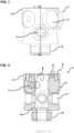
- Figures 1 and 2 show an embodiment of a valve.
- the valve 1 comprises a one-piece valve body 2 with a cover end 3 for connection to a cover 4 and a connection end 5 opposite the cover end 3.
- the valve body 2 has a longitudinal bore 6 extending along its longitudinal axis.
- the longitudinal bore 6 is preferably cylindrical.
- Connection bores 7 running transversely to the longitudinal axis open into the longitudinal bore 6, via which lines can be connected to the valve body 2.
- connection bores 7 include, for example, but are not limited to, connections for extinguishing agents, a connection for a detection line and a connection for a pressure measuring device.
- connection end 5 can comprise a thread via which the valve 1 can be connected to a suction pipe or a suction pipe assembly of a pressure vessel, in particular an extinguishing agent container.
- the suction pipe can be attached to the suction pipe assembly using an internal thread.
- the suction pipe assembly can be designed long enough to function as a suction pipe.
- the suction pipe assembly can be screwed or pressed into the bore of the connection end.
- the bore of the connection end 5 is aligned coaxially with the longitudinal bore 6 of the valve body 2.
- connection end 5 in particular, has a smaller inner diameter than the longitudinal bore 6 of the valve body 2. This forms a circumferential edge 8, which is present between the longitudinal bore 6 of the valve body 2 and the bore of the connection end 5.
- the edge 8 is located axially below a connection bore 7, which is provided, in particular, for connecting an extinguishing line.
- the cover 4 can, as shown in the Figures 5-7
- the valve body 2 can be reversibly connected to the valve body 2 via fastening means.
- the valve body 2 can have corresponding threaded holes 9, into which, for example, screws guided through holes 10 in the cover can be inserted.
- the valve body 2 more precisely in the cover end 3 facing in the axial direction towards the cover 4, there is a circumferential groove 11 for receiving a sealing ring. This allows the cover 4 to be sealingly connected to the valve body 2.
- the cover 2 includes an off-center bore 12 that extends into the valve body 2 when the cover 4 is connected to the valve body 2.
- the bore 12 may have an internal thread. The pneumatic connection of the detection line is possible via the bore 12.
- a preferred piston 13 is shown in side view.
- the piston 13 is, for example, cylindrically shaped and has an end close to the cover and an end close to the connection end, in particular far from the cover.
- a central region 14 of the piston 13 is cylindrical and is flanked by two circumferential grooves 15 or constrictions for respectively receiving a sealing means that can be brought into operative contact with an inner circumferential surface of the valve body 2.
- the diameter of the central region 14 is preferably constant over the length of the piston 13.
- the outer contour of the piston 13 is preferably designed to match the contour of the longitudinal bore 6, so that the piston 13 is axially aligned with the longitudinal axis of the valve body 2.
- the longitudinal bore 6 is movable between a first and a second end position.
- the grooves 15 are located at the end of the piston 13 near the cover and near the connection end, in particular far from the cover.
- the sealing means (not shown) can be made as an O-ring made of an elastomer and is preferably designed such that its diameter is larger than the diameter of the respective groove 15, so that the sealing means protrudes beyond the circumferential surface of the central region 14 of the piston 13.
- the sealing means thus lie sealingly against the inner surface of the longitudinal bore 6.
- the grooves 15 are preferably of the same size. The same applies to the sealing means that can be attached therein. Furthermore, the distance of the grooves 15 from a central axis, which runs transversely to the longitudinal axis of the piston 13, is essentially the same.
- grooves 15 and their position in the piston 13 are preferably mirror-symmetrical with respect to the aforementioned central axis.
- the ends of the piston 13, that is to say the end near the cover and the end near the connection end, in particular the end far from the cover, are delimited by a circumferential edge 16 which forms the free end of the piston 13.
- Piston 13 is penetrated essentially axially along its central axis by a channel 17, which is designed as a stepped bore configuration.
- the transition between the bores forming channel 17 can be conical.
- At least one extinguishing line is connected to the valve 1 via the corresponding connection bore 7 projecting into the valve body 2.
- a A pressure measuring device can be connected to a connection bore 7.
- a detection line is pneumatically connected to the valve body 2 via the bore 10 in the cover 4.
- an extinguishing agent container is pneumatically connected to the valve body 2 via the connection end 5.
- the piston 13 is movably received in the valve body 2, with the sealing means present in the grooves 15 being in operative contact with the inner surface of the valve body 2.
- valve 1 When the valve 1 is connected to a fire fighting and fire suppression system (not shown) as described, the preferred design of the valve 1 causes the piston 13 to be pressed downward in a high-pressure state against the edge 8 formed by the connection end 5, which thus serves as an axial stop, and the piston 13 is in its first stable end position.
- the pressure required for this is generated, for example, via a gas, e.g., nitrogen, introduced into the detection line.
- the piston 13 sits sealingly on the suction pipe assembly so that no extinguishing agent can escape from the pressure vessel.
- the pneumatic area of the end of the piston 13 near the connection end, in particular far from the cover, is smaller than the pneumatic area of the end of the piston 13 near the cover, thereby generating a downward force on the piston 13.
- This state corresponds to normal operation in which the system is not triggered, i.e. no fire has been detected.
- a filling device (not shown) with a corresponding filling device connection can be screwed into the bore 12 in the cover 4.
- the extinguishing agent is conveyed into the pressure vessel via the longitudinal bore 6 of the valve body 2 and the channel 17 extending through the piston 12. It can be advantageous if a sleeve (not shown) is inserted into the longitudinal bore 6 of the valve body 2, which sleeve, on the one hand, lies over the connection bores 7 and, on the other hand, presses the piston 13 into its first end position.
Landscapes
- Health & Medical Sciences (AREA)
- Public Health (AREA)
- Business, Economics & Management (AREA)
- Emergency Management (AREA)
- Fire-Extinguishing By Fire Departments, And Fire-Extinguishing Equipment And Control Thereof (AREA)
- Lift Valve (AREA)
Applications Claiming Priority (2)
| Application Number | Priority Date | Filing Date | Title |
|---|---|---|---|
| DE202023107558.4U DE202023107558U1 (de) | 2023-12-20 | 2023-12-20 | Automatisches Ventil für Brandbekämpfungssysteme |
| DE102024128852 | 2024-10-07 |
Publications (1)
| Publication Number | Publication Date |
|---|---|
| EP4574221A1 true EP4574221A1 (fr) | 2025-06-25 |
Family
ID=93037465
Family Applications (1)
| Application Number | Title | Priority Date | Filing Date |
|---|---|---|---|
| EP24205417.9A Pending EP4574221A1 (fr) | 2023-12-20 | 2024-10-08 | Vanne automatique pour systèmes de lutte contre l'incendie et de lutte contre l'incendie |
Country Status (2)
| Country | Link |
|---|---|
| EP (1) | EP4574221A1 (fr) |
| DE (1) | DE202024105811U1 (fr) |
Citations (6)
| Publication number | Priority date | Publication date | Assignee | Title |
|---|---|---|---|---|
| EP0888152B1 (fr) * | 1996-03-20 | 2001-02-21 | Ceodeux-Fire Extinguisher Valves Technology S.A. | Extincteur et soupape d'extincteur appropriee |
| DE102010028858A1 (de) | 2010-05-11 | 2011-11-17 | Fiwarec Valves & Regulators Gmbh & Co. Kg | Ventil |
| US20120152571A1 (en) * | 2009-06-24 | 2012-06-21 | Luxembourg Patent Company S.A. | A high pressure gas discharge valve for a fire-extinguishing or explosion-preventing system |
| DE102015203486A1 (de) | 2015-02-26 | 2016-09-01 | Minimax Gmbh & Co. Kg | Ventil zum Schalten von Fluiden, Löschanlage und Verfahren |
| US20200114186A1 (en) | 2017-04-04 | 2020-04-16 | Reacton Fire Suppression Limited | Automatic valve |
| EP3744405A1 (fr) | 2019-05-30 | 2020-12-02 | Firetrace Ltd. | Améliorations se rapportant à des soupapes pour systèmes d'extinction d'incendie |
-
2024
- 2024-10-08 EP EP24205417.9A patent/EP4574221A1/fr active Pending
- 2024-10-08 DE DE202024105811.9U patent/DE202024105811U1/de active Active
Patent Citations (6)
| Publication number | Priority date | Publication date | Assignee | Title |
|---|---|---|---|---|
| EP0888152B1 (fr) * | 1996-03-20 | 2001-02-21 | Ceodeux-Fire Extinguisher Valves Technology S.A. | Extincteur et soupape d'extincteur appropriee |
| US20120152571A1 (en) * | 2009-06-24 | 2012-06-21 | Luxembourg Patent Company S.A. | A high pressure gas discharge valve for a fire-extinguishing or explosion-preventing system |
| DE102010028858A1 (de) | 2010-05-11 | 2011-11-17 | Fiwarec Valves & Regulators Gmbh & Co. Kg | Ventil |
| DE102015203486A1 (de) | 2015-02-26 | 2016-09-01 | Minimax Gmbh & Co. Kg | Ventil zum Schalten von Fluiden, Löschanlage und Verfahren |
| US20200114186A1 (en) | 2017-04-04 | 2020-04-16 | Reacton Fire Suppression Limited | Automatic valve |
| EP3744405A1 (fr) | 2019-05-30 | 2020-12-02 | Firetrace Ltd. | Améliorations se rapportant à des soupapes pour systèmes d'extinction d'incendie |
Also Published As
| Publication number | Publication date |
|---|---|
| DE202024105811U1 (de) | 2024-10-28 |
Similar Documents
| Publication | Publication Date | Title |
|---|---|---|
| EP3479008B1 (fr) | Soupape de réservoir | |
| EP0608491B1 (fr) | Limiteur de pression à débit volumineux | |
| EP2011928B1 (fr) | Ensemble anti-retour | |
| DE102015203486A1 (de) | Ventil zum Schalten von Fluiden, Löschanlage und Verfahren | |
| DE102016008059A1 (de) | Tankventil | |
| DE69113265T2 (de) | Schliessventilanordnung. | |
| EP3478995A1 (fr) | Soupape de réservoir | |
| DE4490297B4 (de) | Mit einem druckgesteuerten Ventil versehener Sprühkopf | |
| EP0830181A1 (fr) | Dispositif extincteur a fluide extincteur | |
| DE102016205772B4 (de) | Schnellöffnungsventil für einen druckbeaufschlagten Löschfluidbehälter und Löschfluidbehälter mit selbigem | |
| EP1678434B1 (fr) | Soupape, notamment soupape de securite a gaz | |
| DE10046662B4 (de) | Kraftstoffeinspritzventil mit einem Druckhalteventil | |
| EP4574221A1 (fr) | Vanne automatique pour systèmes de lutte contre l'incendie et de lutte contre l'incendie | |
| EP0666087A1 (fr) | Dispositif de fonctionnement d'un système d'extinction d'incendies | |
| DE102016115360B4 (de) | Überströmventil zum zumindest teilweisen Verschließen und Öffnen eines Fluidleitungssystems | |
| DE3239930A1 (de) | Hydraulisch steuerbares sperrventil, insbesondere fuer die rohrbruchsicherung | |
| WO2026077507A1 (fr) | Vanne automatique pour systèmes de lutte contre l'incendie et d'extinction d'incendie | |
| DE60117387T2 (de) | Durchflussbegrenzungsventil | |
| DE2825165C2 (de) | Steuerbares Ventil für eine Feuerlöschanlage | |
| EP0842102B1 (fr) | Dispositif de soufflage avec unite soupape externe | |
| DE112015000242B4 (de) | Druckreduzier-Ventil für eine Löschanlage sowie Löschanlage mit einem derartigen Druckreduzier-Ventil | |
| EP1688205B1 (fr) | Dispositif de refroidissement des embouts des électrodes | |
| DE763658C (de) | Druckminderventil | |
| DE102016008106A1 (de) | Tankventil | |
| DE2612953C3 (de) | Druckbegrenzungsventil für hydraulische Grubenstempel |
Legal Events
| Date | Code | Title | Description |
|---|---|---|---|
| PUAI | Public reference made under article 153(3) epc to a published international application that has entered the european phase |
Free format text: ORIGINAL CODE: 0009012 |
|
| STAA | Information on the status of an ep patent application or granted ep patent |
Free format text: STATUS: THE APPLICATION HAS BEEN PUBLISHED |
|
| AK | Designated contracting states |
Kind code of ref document: A1 Designated state(s): AL AT BE BG CH CY CZ DE DK EE ES FI FR GB GR HR HU IE IS IT LI LT LU LV MC ME MK MT NL NO PL PT RO RS SE SI SK SM TR |
|
| STAA | Information on the status of an ep patent application or granted ep patent |
Free format text: STATUS: REQUEST FOR EXAMINATION WAS MADE |
|
| 17P | Request for examination filed |
Effective date: 20251219 |