EP4574223A1 - Buté avant pour une fixation de planche de glisse et planche de glisse - Google Patents
Buté avant pour une fixation de planche de glisse et planche de glisse Download PDFInfo
- Publication number
- EP4574223A1 EP4574223A1 EP23219036.3A EP23219036A EP4574223A1 EP 4574223 A1 EP4574223 A1 EP 4574223A1 EP 23219036 A EP23219036 A EP 23219036A EP 4574223 A1 EP4574223 A1 EP 4574223A1
- Authority
- EP
- European Patent Office
- Prior art keywords
- front unit
- bearing elements
- closed position
- open position
- holding
- Prior art date
- Legal status (The legal status is an assumption and is not a legal conclusion. Google has not performed a legal analysis and makes no representation as to the accuracy of the status listed.)
- Pending
Links
Images


Classifications
-
- A—HUMAN NECESSITIES
- A63—SPORTS; GAMES; AMUSEMENTS
- A63C—SKATES; SKIS; ROLLER SKATES; DESIGN OR LAYOUT OF COURTS, RINKS OR THE LIKE
- A63C9/00—Ski bindings
- A63C9/08—Ski bindings yieldable or self-releasing in the event of an accident, i.e. safety bindings
- A63C9/0807—Ski bindings yieldable or self-releasing in the event of an accident, i.e. safety bindings for both towing and downhill skiing
-
- A—HUMAN NECESSITIES
- A63—SPORTS; GAMES; AMUSEMENTS
- A63C—SKATES; SKIS; ROLLER SKATES; DESIGN OR LAYOUT OF COURTS, RINKS OR THE LIKE
- A63C9/00—Ski bindings
- A63C9/08—Ski bindings yieldable or self-releasing in the event of an accident, i.e. safety bindings
- A63C9/084—Ski bindings yieldable or self-releasing in the event of an accident, i.e. safety bindings with heel hold-downs, e.g. swingable
- A63C9/0843—Ski bindings yieldable or self-releasing in the event of an accident, i.e. safety bindings with heel hold-downs, e.g. swingable with a plurality of mobile jaws
-
- A—HUMAN NECESSITIES
- A63—SPORTS; GAMES; AMUSEMENTS
- A63C—SKATES; SKIS; ROLLER SKATES; DESIGN OR LAYOUT OF COURTS, RINKS OR THE LIKE
- A63C9/00—Ski bindings
- A63C9/08—Ski bindings yieldable or self-releasing in the event of an accident, i.e. safety bindings
- A63C9/084—Ski bindings yieldable or self-releasing in the event of an accident, i.e. safety bindings with heel hold-downs, e.g. swingable
- A63C9/0845—Ski bindings yieldable or self-releasing in the event of an accident, i.e. safety bindings with heel hold-downs, e.g. swingable the body or base or a jaw pivoting about a vertical axis, i.e. side release
-
- A—HUMAN NECESSITIES
- A63—SPORTS; GAMES; AMUSEMENTS
- A63C—SKATES; SKIS; ROLLER SKATES; DESIGN OR LAYOUT OF COURTS, RINKS OR THE LIKE
- A63C9/00—Ski bindings
- A63C9/08—Ski bindings yieldable or self-releasing in the event of an accident, i.e. safety bindings
- A63C9/085—Ski bindings yieldable or self-releasing in the event of an accident, i.e. safety bindings with sole hold-downs, e.g. swingable
- A63C9/08507—Ski bindings yieldable or self-releasing in the event of an accident, i.e. safety bindings with sole hold-downs, e.g. swingable with a plurality of mobile jaws
- A63C9/08528—Ski bindings yieldable or self-releasing in the event of an accident, i.e. safety bindings with sole hold-downs, e.g. swingable with a plurality of mobile jaws pivoting about a longitudinal axis
-
- A—HUMAN NECESSITIES
- A63—SPORTS; GAMES; AMUSEMENTS
- A63C—SKATES; SKIS; ROLLER SKATES; DESIGN OR LAYOUT OF COURTS, RINKS OR THE LIKE
- A63C9/00—Ski bindings
- A63C9/08—Ski bindings yieldable or self-releasing in the event of an accident, i.e. safety bindings
- A63C9/085—Ski bindings yieldable or self-releasing in the event of an accident, i.e. safety bindings with sole hold-downs, e.g. swingable
- A63C9/08557—Details of the release mechanism
- A63C9/08585—Details of the release mechanism using transverse biasing element
-
- A—HUMAN NECESSITIES
- A63—SPORTS; GAMES; AMUSEMENTS
- A63C—SKATES; SKIS; ROLLER SKATES; DESIGN OR LAYOUT OF COURTS, RINKS OR THE LIKE
- A63C9/00—Ski bindings
- A63C9/08—Ski bindings yieldable or self-releasing in the event of an accident, i.e. safety bindings
- A63C9/086—Ski bindings yieldable or self-releasing in the event of an accident, i.e. safety bindings using parts which are fixed on the shoe of the user and are releasable from the ski binding
Definitions
- the present invention relates to a front unit for a gliding board binding, in particular for a ski touring binding, and to a gliding board according to the preambles of the independent claims.
- gliding board bindings and in particular, front units for gliding board bindings, are already known from the state of the art.
- binding types for gliding boards such as cross-country bindings, telemark bindings, snowboard and splitboard bindings, and waterski bindings, which perform different functions and whose binding bodies can be designed accordingly.
- Gliding board bindings for skiing typically comprise at least two binding bodies: a heel unit and a toe unit to engage a boot in the downhill position and lock it onto the gliding board.
- Piste bindings are used for downhill skiing and/or skiing on ski lifts.
- Gliding board bindings for ski touring are usually adjustable in two positions: a downhill position, similar to conventional ski bindings, and a touring or ascent position. Touring bindings are primarily used for ascents with the aid of skins attached to the gliding boards.
- a boot In a downhill position, a boot should be reliably locked between the front unit and the heel unit.
- the gliding board binding It should trigger when a defined force is applied to prevent injury, for example, in a fall. At the same time, however, it must ensure that the boot is not released by an increased force caused by an impact or slipping, triggering unintentionally during a descent and, in the worst case, provoking a fall.
- a boot Especially when touring, a boot must be easy to put on, even in difficult terrain or extreme weather conditions. This should be comfortable, error-free, and effortless.
- EP 0 199 098 A2 discloses a touring ski binding comprising a front mount of a touring ski binding for pivotally supporting a ski boot during touring.
- the front mount has two pivotally mounted and opposing clamping parts that are spring-loaded via retaining levers and can be snapped into their locking and rest positions by overcoming a dead center position.
- EP 3 219 368 A2 discloses a front unit for a gliding board, wherein a joint arrangement comprising three joints is provided between the holding sections, which control the pivoting movement relative to each other. The distance between the two outer joints changes during the transition from the held state to the released state. These are rotary or solid-state joints.
- EP 2 392 388 A1 discloses a front unit with two bearing sections configured to engage a boot. Finding the correct entry position for the ski boot is simplified by a longitudinal positioning section.
- the longitudinal positioning section is adjustable between an entry position and a touring position to avoid a collision between the longitudinal positioning section and the pivoting shoe.
- the disadvantage of conventional front units is that they are complex to design and manufacture. Accordingly, the material used and thus production costs are high, and the binding is heavy. The complex construction also makes the binding inflexible and prone to failure - especially in difficult conditions. Any repair or adjustment is made more difficult. In addition, safe entry requires a lot of practice and patience and, in difficult conditions, particularly on steep and/or uneven terrain, presents significant challenges even for experienced users. Furthermore, the entry and release force of the front unit are the same and/or not adjustable. Either a great deal of force must be overcome to enter, or there is a risk that the gliding board binding will inadvertently release during the descent. As a result, many gliding board users block the release of the front unit during the descent.
- the object of the invention is to overcome the disadvantages of the prior art.
- a front unit for a gliding board binding and a gliding board are to be provided that minimizes material usage and thus costs and guarantees reliable engagement of a boot by the gliding board binding. Ease of use is to be maximized while simultaneously increasing the level of safety. Manufacturing costs are to be reduced through easily and simply adjustable and/or replaceable binding components.
- a front unit according to the invention for a gliding board binding, in particular for a ski touring binding, is adjustable between an open position and a closed position.
- the front unit comprises a base with a fastening arrangement for attachment to a gliding board.
- the front unit has two lateral bearing elements which are configured to engage lateral counter-bearing elements of a boot. This holds the boot pivotably about a transverse axis of the gliding board. In the open position, the bearing elements have a distance that is greater than in the closed position. This allows the boot to be inserted or removed between the bearing elements of the front unit.
- the front unit also comprises two retaining levers for moving the bearing elements.
- At least one retaining lever is held on the base so that it can be pivoted about a rotational axis.
- Each retaining lever has a first leg, at the distal end of which one of the bearing elements is arranged. A pivoting movement of the at least one retaining lever enables a relative movement of the bearing elements from the open position to the closed position.
- the retaining levers are operatively connected to each other via a spring mechanism.
- the spring mechanism also serves as a bearing for the two retaining levers.
- gliding board and the terms containing it can refer to skis, but also to a splitboard, snowshoes, or similar boards for walking and/or gliding on snow and ice. Furthermore, gliding boards are for water- and/or sand bases are conceivable, although this list is not exhaustive.
- a bearing element is understood, in particular, to be a pin that, in a closed position, is designed to be in contact with a counter-bearing element in the front area of the boot, allowing the boot to pivot around a gliding board's transverse axis. This makes the front unit particularly suitable for use in a ski touring binding.
- the closed position of the front unit is the position in which the front unit can hold a boot in place using the bearing elements. This applies to both the downhill and touring positions of the gliding board binding.
- the gliding board shoe In the open position, the gliding board shoe is released or insertion of the gliding board shoe is permitted.
- a spring assembly comprising a bearing has the advantage of reducing the number of parts comprising the front unit. This reduces the weight and cost of the front unit, as well as the susceptibility to errors during manufacturing and assembly, and minimizes wear. Safety and operating comfort are increased.
- the bearing element can be cylindrical or conical. However, it can also have any other geometric shape that can come into contact with a corresponding counter-bearing element of a shoe.
- At least one of the retaining levers can be spring-loaded by the spring device.
- the bearing elements can be moved by overcoming a dead center position of at least one of the holding levers is pretensioned into the closed position or into the open position.
- the front unit is not accidentally moved from an open to a closed position, or from a closed to an open position.
- the boot can be reliably engaged in a closed position. A safe and comfortable ascent and/or descent is ensured.
- the closed position is only triggered when specifically desired. Operating comfort is noticeably increased.
- the bearing can be formed by a slotted sleeve.
- the sleeve is preferably made of spring steel. However, an elastomer is also conceivable. Spring steel 1.7103 in accordance with DIN EN 10089 (2003) is preferably used for this purpose, whereby the sleeve can have a diameter in the range of 6.0 mm to 16.0 mm, preferably 8.0 mm to 14.5 mm, particularly preferably 10 mm to 13.0 mm, and a wall thickness of between 0.5 mm and 3.0 mm, preferably 0.75 mm and 2.5 mm, particularly preferably 1.0 mm to 1.5 mm.
- the slot width is between 0.5 mm and 6.0 mm, preferably between 2.0 mm and 5.5 mm, particularly preferably between 3.5 and 5.0 mm.
- the sleeve can have a length of 5.0 to 15.0 mm, preferably 8.0 to 13.0 mm, particularly preferably 10.0 to 12.0 mm.
- Slotted sleeves have the advantage that they can not only serve as connecting elements, but can also absorb impact and shock forces thanks to their spring properties. They can exert continuous pressure on the retaining levers and permanently hold the retaining levers in the open or closed position. They are also easy to install and therefore easy to replace if they become worn. Installation and maintenance costs are low.
- the spring element does not have to have a circular cross-section; other shapes are also conceivable, such as oval, elliptical, triangular, square, or other polygons.
- a single, discrete spring element can be formed between the retaining levers. By forming a single spring element, the design of the front unit can be significantly simplified. This makes the construction more robust and less prone to failure.
- a discrete spring element is an element that exhibits a spring property. For example, it is a spring element made of an elastomer, spring steel, or another suitable elastic material.
- the holding lever can be angled, with a second leg forming an angle of 90° ⁇ 15° with the first leg.
- the first leg has the bearing element at its distal end. The angle is measured between a straight line running along the outer side of the first leg and a second straight line running along the side of the second leg facing the gliding board.
- the length of the second leg can be at least half the distance between the two bearing elements in the closed position. By dimensioning the length of the second leg as large as possible compared to the first leg, a relatively low preload force of the spring device can be achieved. A large force can be achieved on the first leg and thus the clamping force in the closed position.
- the length of the leg is measured from the rotation axis of the holding lever to its distal end.
- a further aspect of the present invention is a front unit for a gliding board binding, preferably as described above.
- the front unit is particularly suitable for a ski touring binding. It is adjustable between an open position and a closed position and comprises a base with a fastening arrangement for attachment to a gliding board. It further comprises two lateral bearing elements configured to engage lateral counter-bearing elements of a boot. This allows the boot to be pivoted about a transverse axis of the gliding board. In the open position, the bearing elements are spaced apart by a greater distance than in the closed position. The boot can thus be inserted between the bearing elements or removed from the front unit.
- the front unit also comprises two retaining levers for moving the bearing elements, with at least one retaining lever being pivotably mounted on the base about a rotational axis.
- Each of the retaining levers has a first leg, at the distal end of which one of the bearing elements is arranged. A pivoting movement of the at least one retaining lever enables a relative movement of the bearing elements from the open position to the closed position.
- the retaining levers are operatively connected to each other via a spring mechanism.
- the front unit also features a longitudinal positioning element for positioning the shoe. The longitudinal positioning element can be pivoted and fixed on an axis perpendicular to the base plane.
- a vertical axis is understood to be an axis that is approximately perpendicular to the gliding board plane
- the vertical axis may deviate from vertical by up to 20°, preferably less than 10°, particularly preferably less than 5°.
- the boot can be carefully and precisely positioned in the front unit, ensuring positioning accuracy within the range of the diameter values of the bearing and counter-bearing elements.
- the longitudinal positioning elements significantly reduce the demands on the user when putting on the boot. Even under difficult conditions such as steep terrain, snow-covered front units, or extreme weather conditions, the boot can be securely engaged by the binding. This makes putting on the boot much easier, faster, and more comfortable, especially for less experienced users and/or in difficult external conditions. By avoiding failed attempts, potential wear on the front unit and thus the service life of the gliding board binding is increased.
- the gliding board binding preferably has two longitudinal positioning elements. However, a single, three, or more longitudinal positioning elements are also conceivable, depending on the design and construction.
- the longitudinal positioning element can be fixed to the base by means of a fastening arrangement.
- the fastening arrangement can preferably comprise a screw thread and a screw. This has the advantage that, after loosening the fastening arrangement, the distance from the bearing elements to the longitudinal positioning element can be adjusted to the shoe model or the degree of wear of the shoe or gliding board. After adjusting the distance, the longitudinal positioning element can be fixed immovably to the base again by means of the fastening arrangement.
- the advantage of fixing the longitudinal positioning elements to the base is that, apart from the longitudinal positioning element with its mounting arrangement, no additional elements are required for adjustment; a simple pivoting around the vertical axis is sufficient. Using standard screws, the longitudinal positioning element can be easily adjusted.
- the longitudinal positioning element may comprise a pin and/or be formed substantially by a pin.
- the material-saving design of the longitudinal positioning element is advantageous, as it reduces weight and manufacturing costs.
- the longitudinal positioning element can also be a plate or have other geometric shapes.
- the front unit may have a locking lever that is adjustable between an unlocked position and a locked position. In the unlocked position, movement from the closed position to the open position is possible, whereas in the locked position, movement from the closed position to the open position is blocked.
- the locking lever In the locked position, the locking lever is in an active position.
- the advantage is that the locking mechanism prevents any transition from a closed position to an open position. This prevents the boot from accidentally being released from the front unit, for example, during a climb.
- the closing actuation lever can be operatively connected to at least one of the retaining levers in such a way that it can force a movement from the closed position to the open position and/or from the open position to the closed position. This allows for a targeted opening and/or closing of the binding.
- the bearing elements can thus be deliberately and controlledly brought into engagement with the counter-bearing elements of a boot.
- a further aspect of the present invention is a front unit for a gliding board binding, particularly as described above.
- the gliding board binding is particularly suitable as a ski touring binding.
- the front unit is adjustable between an open position and a closed position and comprises a base with a fastening arrangement for attachment to a gliding board.
- the front unit further comprises two lateral bearing elements configured to engage lateral counter-bearing elements of a boot. The boot is thereby held pivotably about a gliding board transverse axis. In the open position, the bearing elements are spaced apart by a distance that is greater than in the closed position. The boot can thus be inserted between the bearing elements or removed from the front unit.
- the front unit also comprises two retaining levers for moving the bearing elements, wherein at least one retaining lever, preferably both retaining levers, is held on the base so as to be pivotable about a rotational axis.
- Each of the retaining levers has a first leg, at the distal end of which one of the bearing elements is arranged. A pivoting movement of the retaining lever enables a relative movement of the bearing elements from the open position to the closed position.
- the retaining levers are operatively connected to each other via a spring mechanism. The preload of the retaining levers in the open position differs from the preload in the closed position.
- the force required to overcome a dead center from the open position to the closed position is smaller than from the closed position to the open position.
- the force can be adjustable. Under this condition, different configurations are conceivable. In at least one configuration, the force from the open position to the closed position must be smaller than the force from the closed position to the open position. However, configurations are also conceivable in which the force can be the same or greater.
- the position of the spring device can be adjusted relative to the gliding board plane.
- the elastic element can be located in the base of the front unit. Using an adjusting element, such as a screw, the tension of the elastic element, which acts on the connecting rod and thus on the spring device, can be adjusted.
- an adjusting element such as a screw
- Another object of the present invention relates to a gliding board with a front unit as described above.
- the base and/or the retaining levers of the front unit may be made of a metal.
- the metal may be selected from the group comprising precious metal, steel, spring steel, and/or aluminum. and alloys thereof. Plastic-based and/or fiber-reinforced materials are also conceivable. A design of the front unit without plastic is also conceivable.
- the advantage of choosing metal is that the gliding board binding can withstand greater forces and increases its durability. Accordingly, the gliding board binding, including all individual components, can be recycled at the end of its life.
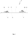
- Figure 1 shows a side view of a gliding board 1 with a gliding board binding 2, which has a front unit 10 and a heel unit 20.
- the gliding board binding 2 is particularly suitable as a binding for ski touring skis.
- the binding 2 is in a downhill position.
- the front unit 10 and the heel unit 20 are arranged along a gliding board longitudinal axis L on attached to the gliding board 1.
- a base 11 of the front unit 10 and a base 21 of the heel unit 20 are arranged on the gliding board 1 and serve to mount the two binding units.
- the base 11 has a base plane E and the base 21 has a base plane F.
- the front unit 10 and the heel unit 20 are mounted on the side opposite the gliding surface G of the gliding board 1.
- a gliding board plane H coincides with the base planes E and F.
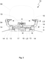
- FIG 2 shows a perspective view and Figure 3 in a front view of the front unit 10 according to Figure 1 in an open position.
- the front unit 10 according to the invention is adjustable into an open and a closed position.
- the front unit 10 is attached to the gliding board 1 by means of its base 11 by means of a fastening arrangement 12.
- the fastening arrangement 12 is formed by a screw hole, which enables the front unit 10 to be mounted on the gliding board 1 via the base 11 and the base plane E by means of screws (not shown).
- the front unit 10 has two lateral retaining levers 13 with a first leg 14 and a second leg 14'.
- a bearing element 15 in the form of a pin is attached to the distal end of each retaining lever 13.
- the bearing elements 15 are arranged substantially parallel to a gliding board transverse axis Q and orthogonal to the first legs 14.
- the bearing elements 15 In the closed position (not shown), the bearing elements 15 can engage lateral counter-bearing elements 54 of a shoe 50.
- the shoe 50 is thus held pivotably about a gliding board transverse axis Q.
- the distance K between the pins 15 is greater than the distance I between the counter-bearing elements 54 of the shoe 50.
- the two retaining levers 13 are spring-loaded by a spring device 16 and interact with each other.
- the spring device 16 is a slotted sleeve made of spring steel.
- the slotted sleeve also serves as a bearing 17 for the two retaining levers 13.
- the retaining levers 13 are preloaded into the illustrated open position by the spring device 16.
- the retaining levers 13 are mounted on the base 11 so as to be pivotable about a rotation axis D.
- the bearing elements 15 By overcoming an unstable dead center position of the two retaining levers 13, the bearing elements 15 can be preloaded from the open position to the closed position and engage the shoe 50 for ascent or descent.
- the distance K between the two bearing elements 15 then essentially corresponds to the distance between the counter bearings 54 of the shoe 50.
- the force required to overcome the dead center position depends on the position of the retaining levers 13. The closer the retaining levers are to the dead center, the lower the force required to overcome the dead center. Of course, the force required to overcome the dead center also depends on the design and dimensioning of the spring device 16.
- the illustrated front unit 10 also includes two longitudinal positioning elements 100, which are designed as pins.
- the longitudinal positioning elements 100 are fixed to the base 11 of the gliding board 1 by means of a fastening arrangement 101.
- the fastening arrangement 101 comprises a screw for mounting the longitudinal positioning elements 100 to the base 11.
- the longitudinal positioning elements 100 can be pivoted about an axis V4, V5 perpendicular to the base plane E.
- the longitudinal positioning elements 100 enable precise positioning of the shoe 50 in the front unit 10.
- the position The longitudinal positioning elements 100 can be adapted to a shoe model and/or wear of the shoe 50, so that the positioning accuracy of a shoe 50 lies within the range of the diameter values of the bearing elements 15 and the counter-bearing elements 54.
- the shoe 50 can be easily and safely positioned and engaged between the bearing elements 15, even under difficult conditions.
- the front unit 10 further comprises a closing actuating lever 18, which interacts with an adjusting section 19.
- the closing actuating lever 18 is adjustable between an unlocked position, in which the movement of the adjusting section 19 is not impeded, and a locked position, in which the adjusting section 19 is blocked in a locked position.
- the adjusting section 19 is in direct operative connection with the bearing 17 and/or the second legs 14' of the holding levers 13. In the locked position, the movement of the holding levers 13 is also blocked, so that a safety release of the front unit 10 is blocked.
- the closing actuating lever 18 In a touring position, which is preferably set during ascents, the closing actuating lever 18 is usually in this locked position. During descents, the closing actuating lever 18 is preferably used in the unlocked position.
- the actuating section 19 is not obstructed, and the movement of the bearing 17 and/or the second legs 14' is not impaired. In the event of a large force, a safety release is possible.
- the second legs 14' and the bearing 17 can be displaced in the direction of the base plane E.
- the dead center is overcome and the bearing elements 15 engage with the counter-bearing elements 54 of the shoe 50.
- the distance K between the bearing elements 15 then essentially corresponds to the distance between the counter-bearing elements 54 of the shoe 50.
- the spring device 16 accordingly pre-tensions the holding levers 13 into the closed position so that the shoe 50 is held in place. Since the bearing 17 is already close to the dead center in the open position, only a small amount of force is required to overcome the dead center.
- the holding lever 13 has an angle ⁇ of 80° between the first leg 14 and the second leg 14'.
- the length of the second leg 14' is greater than the length of the first leg 14.
- the length of the shanks is measured from the axis of rotation D of the holding lever 13 to the distal end of the first or second leg 14, 14'.
- the length LS' of the second leg 14' is greater than the distance K between the two bearing elements 15 in the open position.
- Figure 4 shows a cross-section in the longitudinal direction L of a gliding board through the front unit 10 according to another embodiment.
- the front unit 10 is shown in the open position and essentially corresponds to the front unit 10 according to Figure 2 .
- the front unit 10 has an additional element which influences the preload of the holding levers 13.
- Schematically shown is a connecting mechanism 90 which acts as a second superimposing force on the Preload of the holding lever 13 acts.
- the connecting mechanism 90 is arranged between the base 11 and the spring device 16 and can be adjusted.
- a connecting rod 91, as part of the connecting mechanism 90, acts on the spring device 16 and on an elastic element 92 which is connected to the base 11.
- the connecting mechanism 90 By means of the connecting mechanism 90, the position of the spring device 16 relative to the base plane E and thus also to the dead center can be adjusted. A distance between the spring device 16 and the base plane E, and thus the distance to the dead center, can be adjusted, for example, by means of a screw 93. Furthermore, the force of the elastic element 92, which acts on the connecting rod 91 and thus on the spring device 16, is adjusted by means of the screw 93.
- another spring element such as a sleeve with a larger wall thickness, can be used to adjust the preload.
Landscapes
- Footwear And Its Accessory, Manufacturing Method And Apparatuses (AREA)
- Fittings On The Vehicle Exterior For Carrying Loads, And Devices For Holding Or Mounting Articles (AREA)
Priority Applications (2)
| Application Number | Priority Date | Filing Date | Title |
|---|---|---|---|
| EP23219036.3A EP4574223A1 (fr) | 2023-12-21 | 2023-12-21 | Buté avant pour une fixation de planche de glisse et planche de glisse |
| PCT/EP2024/087976 WO2025133170A1 (fr) | 2023-12-21 | 2024-12-20 | Unité avant pour fixation de planche de glisse et planche de glisse |
Applications Claiming Priority (1)
| Application Number | Priority Date | Filing Date | Title |
|---|---|---|---|
| EP23219036.3A EP4574223A1 (fr) | 2023-12-21 | 2023-12-21 | Buté avant pour une fixation de planche de glisse et planche de glisse |
Publications (1)
| Publication Number | Publication Date |
|---|---|
| EP4574223A1 true EP4574223A1 (fr) | 2025-06-25 |
Family
ID=89430076
Family Applications (1)
| Application Number | Title | Priority Date | Filing Date |
|---|---|---|---|
| EP23219036.3A Pending EP4574223A1 (fr) | 2023-12-21 | 2023-12-21 | Buté avant pour une fixation de planche de glisse et planche de glisse |
Country Status (2)
| Country | Link |
|---|---|
| EP (1) | EP4574223A1 (fr) |
| WO (1) | WO2025133170A1 (fr) |
Citations (5)
| Publication number | Priority date | Publication date | Assignee | Title |
|---|---|---|---|---|
| EP0199098A2 (fr) | 1985-03-25 | 1986-10-29 | Fritz Dipl.-Ing. Barthel | Fixation pour ski de randonnée |
| EP2392388A1 (fr) | 2010-06-02 | 2011-12-07 | Salewa Sport AG | Fixation de randonnée |
| US9039031B2 (en) * | 2012-07-19 | 2015-05-26 | Salomon S.A.S. | Front retaining devices for a gliding board |
| EP3219368A2 (fr) | 2016-03-18 | 2017-09-20 | Fritz Barthel | Unité avant pour planche de glisse |
| EP3782707A1 (fr) * | 2019-07-29 | 2021-02-24 | Atk Sports S.R.L. | Butée avant d'une fixation de ski de randonnee |
-
2023
- 2023-12-21 EP EP23219036.3A patent/EP4574223A1/fr active Pending
-
2024
- 2024-12-20 WO PCT/EP2024/087976 patent/WO2025133170A1/fr active Pending
Patent Citations (5)
| Publication number | Priority date | Publication date | Assignee | Title |
|---|---|---|---|---|
| EP0199098A2 (fr) | 1985-03-25 | 1986-10-29 | Fritz Dipl.-Ing. Barthel | Fixation pour ski de randonnée |
| EP2392388A1 (fr) | 2010-06-02 | 2011-12-07 | Salewa Sport AG | Fixation de randonnée |
| US9039031B2 (en) * | 2012-07-19 | 2015-05-26 | Salomon S.A.S. | Front retaining devices for a gliding board |
| EP3219368A2 (fr) | 2016-03-18 | 2017-09-20 | Fritz Barthel | Unité avant pour planche de glisse |
| EP3782707A1 (fr) * | 2019-07-29 | 2021-02-24 | Atk Sports S.R.L. | Butée avant d'une fixation de ski de randonnee |
Also Published As
| Publication number | Publication date |
|---|---|
| WO2025133170A1 (fr) | 2025-06-26 |
Similar Documents
| Publication | Publication Date | Title |
|---|---|---|
| DE4135899C2 (de) | Schibindung mit einer Längenverstellvorrichtung für den Abstand zwischen dem Vorder- und Fersenbacken | |
| DE3310739C2 (fr) | ||
| DE9421380U1 (de) | Snowboardbindung | |
| EP2319596B1 (fr) | Mâchoire avant pour une fixation de ski de fond et chaussure de ski pour une fixation de ski de fond | |
| CH684315A5 (de) | Verbindungseinrichtung, insbesondere zum Befestigen eines Schischuhes auf einer Oberfläche eines Schi. | |
| DE2656635A1 (de) | Ausloeseskibindung | |
| DE102012208915B4 (de) | Ferseneinheit mit Steighilfe und Bremsanordnung | |
| EP2638937A1 (fr) | Unité de talon pour une fixation de ski de randonée | |
| DE102011079210A1 (de) | Ferseneinheit für eine Tourenskibindung | |
| DE3151584A1 (de) | Bindungsgesamtheit eines schuhs mit einem ski, insbesondere einem langlaufski | |
| EP3928842B1 (fr) | Unité avant pour une fixation de randonnée | |
| EP2452731B1 (fr) | Fixation de randonnée dotée d'un mécanisme de déclenchement et d'un mécanisme de verrouillage | |
| EP1097732A2 (fr) | Fixation pour planche de glisse, notamment snowboards | |
| WO1984000498A1 (fr) | Fixation de securite pour skis | |
| EP3906980B1 (fr) | Talonnière pour une fixation de ski | |
| DE1678260A1 (de) | Skibindung | |
| DE3227237C1 (de) | Sicherheitsbindung für Ski | |
| EP4574223A1 (fr) | Buté avant pour une fixation de planche de glisse et planche de glisse | |
| DE2600858C3 (de) | Skisicherheitsbindung mit einer mit dem Schuh lösbar verbundenen Trittplatte | |
| EP4452430B1 (fr) | Système de fixation pour une fixation de ski de randonnée | |
| EP2821114B1 (fr) | Système de fixation de sécurité | |
| DE3227232C2 (de) | Fersenhalterung für eine Langlaufskibindung | |
| EP4417276B1 (fr) | Mâchoire avant et fixation de sécurité de ski dotée d'une mâchoire avant | |
| EP4574222A1 (fr) | Talonniere pour une fixation de planche de glisse et planche de glisse | |
| AT410176B (de) | Bindungskonstruktion |
Legal Events
| Date | Code | Title | Description |
|---|---|---|---|
| PUAI | Public reference made under article 153(3) epc to a published international application that has entered the european phase |
Free format text: ORIGINAL CODE: 0009012 |
|
| STAA | Information on the status of an ep patent application or granted ep patent |
Free format text: STATUS: THE APPLICATION HAS BEEN PUBLISHED |
|
| AK | Designated contracting states |
Kind code of ref document: A1 Designated state(s): AL AT BE BG CH CY CZ DE DK EE ES FI FR GB GR HR HU IE IS IT LI LT LU LV MC ME MK MT NL NO PL PT RO RS SE SI SK SM TR |
|
| STAA | Information on the status of an ep patent application or granted ep patent |
Free format text: STATUS: THE APPLICATION IS DEEMED TO BE WITHDRAWN |