EP4574231A1 - Filtermaterial und verfahren zur bereitstellung eines filtermaterials - Google Patents
Filtermaterial und verfahren zur bereitstellung eines filtermaterials Download PDFInfo
- Publication number
- EP4574231A1 EP4574231A1 EP23217632.1A EP23217632A EP4574231A1 EP 4574231 A1 EP4574231 A1 EP 4574231A1 EP 23217632 A EP23217632 A EP 23217632A EP 4574231 A1 EP4574231 A1 EP 4574231A1
- Authority
- EP
- European Patent Office
- Prior art keywords
- nonwoven
- fibers
- section
- filter material
- fiber
- Prior art date
- Legal status (The legal status is an assumption and is not a legal conclusion. Google has not performed a legal analysis and makes no representation as to the accuracy of the status listed.)
- Pending
Links
Images

Classifications
-
- B—PERFORMING OPERATIONS; TRANSPORTING
- B01—PHYSICAL OR CHEMICAL PROCESSES OR APPARATUS IN GENERAL
- B01D—SEPARATION
- B01D39/00—Filtering material for liquid or gaseous fluids
- B01D39/14—Other self-supporting filtering material ; Other filtering material
- B01D39/16—Other self-supporting filtering material ; Other filtering material of organic material, e.g. synthetic fibres
- B01D39/1607—Other self-supporting filtering material ; Other filtering material of organic material, e.g. synthetic fibres the material being fibrous
- B01D39/1623—Other self-supporting filtering material ; Other filtering material of organic material, e.g. synthetic fibres the material being fibrous of synthetic origin
- B01D39/163—Other self-supporting filtering material ; Other filtering material of organic material, e.g. synthetic fibres the material being fibrous of synthetic origin sintered or bonded
-
- B—PERFORMING OPERATIONS; TRANSPORTING
- B01—PHYSICAL OR CHEMICAL PROCESSES OR APPARATUS IN GENERAL
- B01D—SEPARATION
- B01D2239/00—Aspects relating to filtering material for liquid or gaseous fluids
- B01D2239/02—Types of fibres, filaments or particles, self-supporting or supported materials
- B01D2239/0216—Bicomponent or multicomponent fibres
-
- B—PERFORMING OPERATIONS; TRANSPORTING
- B01—PHYSICAL OR CHEMICAL PROCESSES OR APPARATUS IN GENERAL
- B01D—SEPARATION
- B01D2239/00—Aspects relating to filtering material for liquid or gaseous fluids
- B01D2239/06—Filter cloth, e.g. knitted, woven non-woven; self-supported material
- B01D2239/0604—Arrangement of the fibres in the filtering material
- B01D2239/0618—Non-woven
-
- B—PERFORMING OPERATIONS; TRANSPORTING
- B01—PHYSICAL OR CHEMICAL PROCESSES OR APPARATUS IN GENERAL
- B01D—SEPARATION
- B01D2239/00—Aspects relating to filtering material for liquid or gaseous fluids
- B01D2239/06—Filter cloth, e.g. knitted, woven non-woven; self-supported material
- B01D2239/0604—Arrangement of the fibres in the filtering material
- B01D2239/0622—Melt-blown
-
- B—PERFORMING OPERATIONS; TRANSPORTING
- B01—PHYSICAL OR CHEMICAL PROCESSES OR APPARATUS IN GENERAL
- B01D—SEPARATION
- B01D2239/00—Aspects relating to filtering material for liquid or gaseous fluids
- B01D2239/06—Filter cloth, e.g. knitted, woven non-woven; self-supported material
- B01D2239/0604—Arrangement of the fibres in the filtering material
- B01D2239/0627—Spun-bonded
-
- B—PERFORMING OPERATIONS; TRANSPORTING
- B01—PHYSICAL OR CHEMICAL PROCESSES OR APPARATUS IN GENERAL
- B01D—SEPARATION
- B01D2239/00—Aspects relating to filtering material for liquid or gaseous fluids
- B01D2239/06—Filter cloth, e.g. knitted, woven non-woven; self-supported material
- B01D2239/0604—Arrangement of the fibres in the filtering material
- B01D2239/0636—Two or more types of fibres present in the filter material
-
- B—PERFORMING OPERATIONS; TRANSPORTING
- B01—PHYSICAL OR CHEMICAL PROCESSES OR APPARATUS IN GENERAL
- B01D—SEPARATION
- B01D2239/00—Aspects relating to filtering material for liquid or gaseous fluids
- B01D2239/06—Filter cloth, e.g. knitted, woven non-woven; self-supported material
- B01D2239/0604—Arrangement of the fibres in the filtering material
- B01D2239/064—The fibres being mixed
-
- B—PERFORMING OPERATIONS; TRANSPORTING
- B01—PHYSICAL OR CHEMICAL PROCESSES OR APPARATUS IN GENERAL
- B01D—SEPARATION
- B01D2239/00—Aspects relating to filtering material for liquid or gaseous fluids
- B01D2239/10—Filtering material manufacturing
-
- B—PERFORMING OPERATIONS; TRANSPORTING
- B01—PHYSICAL OR CHEMICAL PROCESSES OR APPARATUS IN GENERAL
- B01D—SEPARATION
- B01D2239/00—Aspects relating to filtering material for liquid or gaseous fluids
- B01D2239/12—Special parameters characterising the filtering material
- B01D2239/1233—Fibre diameter
-
- B—PERFORMING OPERATIONS; TRANSPORTING
- B01—PHYSICAL OR CHEMICAL PROCESSES OR APPARATUS IN GENERAL
- B01D—SEPARATION
- B01D2239/00—Aspects relating to filtering material for liquid or gaseous fluids
- B01D2239/12—Special parameters characterising the filtering material
- B01D2239/1266—Solidity
Definitions
- the invention relates to a filter material and a method for providing such filter material.
- Filter materials are used for a variety of technical tasks. Typically, they are used for separating particles from a fluid, i.e. from a liquid or a gas.
- the particles can be solid particles, they can also be drops of a liquid which is not mixable with the fluid.
- a filter material usually has an upstream side and a downstream side. On the upstream side, the fluid loaded with the particles meets the filter surface. As the fluid flows through the filter, the particles are retained by the filter. On the downstream side, the fluid leaves the filter material again and is at least partially cleaned, i.e. it now contains an at least reduced amount of the particles, if it is not free from particles. In this context, typically, a distinction is made between surface filtration (separative filtration) and deep filtration (storage filtration).
- the respective fiber structure can take on a separate function.
- the fiber structure having a low fiber density on the inflow side serves as a depth filter with a high particle storage capacity.
- the high packing density creates a filter with improved filter efficiency.
- the advantages of the combination are a significantly increased filter service life, with less manufacturing effort and therefore lower production costs.
- Coarser fibers are used on the upstream side and finer fibers on the downstream side.
- the coarse fibers reduce the specific surface area of the fibers on the upstream side and the average pore size increases thereby.
- This concept increases the dust storage capacity by increasing the number of layers of fibers and the resulting empty space.
- the average pore size of the filter is reduced by reducing the fiber diameter and the filter separation efficiency is improved due to the barrier effect of the fiber.
- the number of fiber layers per height segment and the reduction in pore size achieved thereby determine the filter efficiency.
- Fine fiber filter media having a multilayer gradient structure are known, for example, US 10 155 186 B2 .
- the filter media is a fiber web comprising: a first layer and a second layer, wherein each of the first and second layers comprises a plurality of meltblown fibers having an average fiber diameter between about 0.1 microns and about 1.5 microns.
- the fiber diameter influences the pore size of such filter media which results in different filtering characteristics. While a coarse filter material - having typically a larger pore size - usually provides a high air permeability, finer filter media - having typically a smaller pore size - do provide higher filtering efficiency. Nevertheless, it is usually desired to have a high air permeability as well as high filtering efficiency and a high dust holding capacity.
- US 10 828 587 B2 discloses staple fiber filter media including nanofibers.
- filter media comprising: a first fiber web having an average fiber diameter of less than or equal to about 0.5 microns and a maximum pore size of less than or equal to about 1.0 microns; and a second fiber web having a maximum pore size of greater than or equal to about 3 microns and less than or equal to about 70 microns.
- filter media comprising several filter layers, wherein the filter layers do have different pore sizes
- several layers of filter media are, usually, manufactured individually, then stacked and, subsequently, connected to each other.
- the layers are laminated to each other. Accordingly, a clearly distinctive separation surface is formed between the so connected layers.
- the purpose of pleating is to achieve improved filtration by increasing the exposed filter surface per square area.
- the media is subjected to high bending and stretching forces. These mechanical stresses are particularly substantial in two or multiple layer media.
- Layers comprising distinct fiber diameters show distinct mechanical strength and elasticity. Thus, stress peaks act on the interfaces. At the edged surface of the pleat, a fine fiber layer might rupture or delaminate from a coarse back layer. Such defects can result in a reduction of the filter's efficiency.
- a technical objective to provide a mechanically stiff nonwoven material for filtration.
- the material shall be pleatable while showing a high air permeability, a high dust holding capacity and a high filtering efficiency.
- the filtration media shall be resilient against attrition and wastage induced by defects such as delamination, abrasion, and rupture by the fluid flow and shall show a decreased level of pore clogging.
- the object of the present invention is a single layer nonwoven filter material (10) having:
- the filter material according to the instant invention is a material that is usable for separating particles from a fluid or for coalescence applications, said fluids can be a gas or a liquid.
- the particles can be solid particles or drops of liquids or e.g. dust particles.
- the particles can be oil drops and the fluid can be a gaseous fluid, i.e. the fluid to be cleaned can be an oil mist.
- the size of the particles can vary.
- the filter material has typically an upstream side and a downstream side.
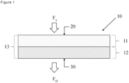
- the first surface (20) being the upstream side of the filter material and the second surface (30) being the downstream side of the filter material.
- the upstream side is the outer surface of the filter material that faces towards an arriving fluid stream, which is loaded with particles.
- the fluid stream F u enters the filter material and from there passes through the filter. While passing through the filter the particles are retained by the filter material and - in an ideal case - only the fluid is allowed to pass. The so cleared fluid leaves the filter at the downstream side F D .
- the downstream side (30) is the side of the filter, which faces the direction in which the fluid flows away from the filter.
- Nonwoven, sometimes also called nonwoven fabrics are web structures made by entangling more or less randomly arranged fibers or filaments by mechanical, thermal, chemical or solvent means.
- Nonwovens can be made from staple fiber and/or continuous fibers such as filaments. Filaments are continuous fiber strands.
- nonwovens are typically made of randomly arranged and bonded fibers, wherein the fibers can be short staple fibers or long continuous filament fibers.
- Preferred examples of nonwovens in this context are spunbond nonwovens and meltblown nonwovens. Spunbond nonwovens are made in one continuous process. Fibers are spun and then directly dispersed into a web, e.g. by the help of a deflector or by the help of a directed air stream. Melt-blown nonwovens are typically produced by extruding melted polymer fibers through a spinneret or die assembly.
- the nonwoven filter material of the instant invention is a single layer nonwoven filter material.
- single layer refers to a nonwoven filter material manufactured in a single manufacturing step without manufacturing separate filter material layers and combining, attaching, adhering or compounding these in a subsequent or additional manufacturing step.
- single layer nonwoven shall limit the literal understanding to a nonwoven filter material layer composed of or consisting of one type of polymeric fibers or one homogeneous blend of two or more different fibers, said blend includes polymeric fibers, in particular melt-spun polymer fibers, throughout the thickness of the nonwoven layer.
- the aforementioned blend includes, beside the polymeric fibers, in particular melt-spun polymer fibers, other fibers, such as glass fibers or cellulose fibers, typically in an amount of up to 30 wt.-% based on the total weight of the nonwoven.
- glass fibers instead of the glass fibers, also mineral fibers based on alumino silicate, ceramic, dolomite fibers or fibers of vulcanites, such as e.g. basalt diabase, melaphyre diabase (greenstone) and melaphyres (so-called paleobasalts) can also be used. Glass fibers are preferred however on account of their economic availability.
- the glass fibers are not subject to any substantial restriction with regard to the type of glass, so that in principle all types of glass such as E glass, S glass, R glass, and C glass may be used. For economic reasons E glass or C glass is preferred. Biosoluble glasses are particularly preferred.
- the glass fibers may be formed from filaments, that is to say fibers of infinite length or from staple fibers.
- the length of the staple fibers is between 0.3 and 100 mm, more preferred between 3 to 18 mm.
- the composition and amount of fusible or reactive binder adhered to the fibers in the inner area (13) is homogeneously distributed throughout the inner area (13), binder composition and amount are in particular the same in the first section (11) and in the second section (12).
- the single layer nonwoven filter material (10) is a non-woven which can be made up of various synthetic polymer fibers.
- the non-woven can be a wet laid non-woven, a dry-laid non-woven or a spunbonded nonwoven or a melt-blown nonwoven. Such non-woven can be consolidated by means of chemical bonding as well as, if necessary, thermal and/or mechanical consolidation.
- the non-woven can be staple fiber non-woven or spunbonded nonwoven of filaments.
- Suitable polymer materials are, for example, thermoplastics, preferably polyamides, such as polyhexamethylene-diadipamide, polycaprolactam, aromatic or partially aromatic polyamides ("aramides"), aliphatic polyamides, such as nylon, partially aromatic or fully aromatic polyesters, aliphatic polyesters, polycarbonates (PC), polyphenylene sulphide (PPS), polyphenylene oxide (PPO), polystyrene (PS), polyvinyl carbazole (PVK), polyacetal (POM), polyaryl ether, polyaryl sulphone, polyether sulphone, polymers with ether and keto-groups, such as polyether ketones (PEK) and polyether etherketone (PEEK), polyolefins, such as polyethylene or polypropylene, or polybenzimidazoles. Particularly preferred are polyester, polyolefins, such as e.g. polyethylene or polypropylene, or aromatic or partially aromatic polyamides (“aramids
- the spunbonded nonwoven preferably comprise or are composed of melt-spinnable polyesters.
- the polyester material can, in principle, be any known type suitable for fiber production.
- Such polyesters consist predominantly of components derived from aromatic dicarboxylic acids and from aliphatic diols.
- aromatic dicarboxylic acid components are bivalent residues of benzenedicarboxylic acids, especially of terephthalic acid and of isophthalic acid; commonly used diols have 2 to 4 carbon atoms, wherein ethylene glycol is particularly suitable.
- Spunbonded fabrics which consist of at least 85 mole % of polyethylene terephthalate are particularly advantageous.
- dicarboxylic acid moieties and glycol moieties which act as so-called modifiers and allow the person skilled in the art to specifically influence the physical and chemical properties of the produced filaments.
- dicarboxylic acid units are residues of isophthalic acid or of aliphatic dicarboxylic acid, such as glutaric acid, adipic acid, and sebacic acid;
- modifying diol residues are those composed of longer-chain diols, such as propane diol or butane diol, of diethylene or triethylene glycol or, if present in small quantities, of polyglycol with a molar weight of approximately 500 to 2000.
- aliphatic polyesters Beside the partially aromatic or fully aromatic polyesters, also aliphatic polyesters can be used. Such polymers are materials obtained from renewable resources and are so-called bio-based materials which, typically, are bio-degradable polymer materials. A well-known member of such aliphatic polyesters is poly-lactic acid (PLA) based thermoplastic resin or Polybutylensuccinat (PBS).
- PLA poly-lactic acid
- PBS Polybutylensuccinat
- Polyesters containing at least 95 mol % of polyethylene terephthalate (PET) are particularly preferred, especially those composed of unmodified PET.
- the polyesters contained in the spunbonded nonwoven preferably have a molecular weight corresponding to an intrinsic viscosity (IV) of 0.6 to 1.4, measured in a solution of 1 g polymer in 100 ml dichloroacetic acid at 25 °C.
- IV intrinsic viscosity
- polymers from which the carrier fibers can be derived are polyacrylonitrile, polyolefins, such as polyethylene or polypropylene, primarily aliphatic polyamides, such as nylon 6.6, primarily aromatic polyamides (aramids), such as poly-(p-phenylene terephthalate) or copolymers containing a content of aromatic m-diamine moieties to improve the solubility, or poly-(m-phenylene isophthalate), primarily aromatic polyesters, such as poly-(p-hydroxybenzoate), or preferably primarily aliphatic polyesters, such as polyethylene terephthalate.
- polyacrylonitrile polyolefins, such as polyethylene or polypropylene
- aromatic polyamides (aramids) such as poly-(p-phenylene terephthalate) or copolymers containing a content of aromatic m-diamine moieties to improve the solubility
- the relative proportion of the two fiber types may be selected within wide limits, whilst making sure that the proportion of the hot melt adhesive fibers is sufficient to bond the carrier fibers to the hot melt adhesive fibers, thereby endowing the nonwoven fabric with a strength sufficient for the intended application, whilst on the other hand ensuring the necessary air permeability.
- the proportion of the hot-melt derived from the hot-melt fiber in the non-woven is usually less than 50% by weight (based upon the weight of the non-woven).
- Modified polyesters having a melting point 10 to 50 °C, preferably 30 to 50 °C, lower than the raw material of the non-woven are particularly suitable as hot melt adhesive.
- hot melt adhesive examples include polybutylene terephthalate, or polyethylene terephthalate modified by the condensation of longer-chain diols and/or isophthalic acid or aliphatic dicarboxylic acid.
- polyolefine, such as polyethylene and/or polypropylene can be used as hot melt adhesive.
- the hot melt adhesives are preferably incorporated into the non-woven in fibrous form.
- the carrier fibers and hot melt adhesive fibers are preferably made up of one class of polymers. This implies that all of the fibers used are selected from one class of substances, so that these can readily be recycled after the non-woven has been used.
- the carrier fibers consist of polyester, for example, the hot melt adhesive fibers selected will likewise be of polyester or a mixture of polyesters, for example in the form of bi-component fibers with PET in the core and a polyethylene terephthalate copolymer having a low melting point as sheath.
- bi-component fibers which are made up of different polymers are also possible. Examples of these are bi-component fibers of polyester and polyamide (core/sheath).
- the monofilament titre of the carrier fibers and the hot melt adhesive fibers may be selected within said limits.
- the filaments or staple fibers making up the non-woven may have a virtually circular cross section or may also have other shapes, such as dumb bell-shaped, reniform, triangular, trilobal or multilobal cross sections. Hollow fibers and bi-component or multi-component fibers may also be used. Furthermore, the hot-melt adhesive fiber may also be used in the form of bi-component or multi-component fibers.
- Types of bi-component fiber shapes are core/sheath, core/sheath eccentric, side by side full, side by side hollow, side by side hollow eccentric, orange type with center or without center, striped, island in the sea, profile and mixed bi-component fibers.
- the ratio between the two bi-component materials is in the range of 30 wt.% to 90 wt.% of the higher melt point temperature component A and 10 wt.% to 70 wt.% of lower melt temperature component B.
- Typical ratios A to B can vary in the range of 30/70 wt.% to 80/20 wt.%, 30/70 wt.% to 70/30 wt.%, 50/50 wt.% to 70/30 wt.%, 65/35 wt.% to 80/20 wt.% and 30/70 wt.% to 90/10 wt%.
- the fibers forming the non-woven may also be modified by means of the usual additives, for example by antistatic agents such as carbon black, or additives which will permit an electrostatic charge. Furthermore, the fibers can have antimicrobial equipment.
- the weight per unit area of the single layer non-woven is between 20 and 500 g/m 2 , preferably 40 and 400 g/m 2 , particularly 90 and 250 g/m 2 .
- the single layer non-woven may contain binding fibers which allow for a thermal consolidation, e.g. by calendering or in a hot air oven in a manner known per se.
- the fibers can also have a bi-component structure (e.g. core/sheath), in which the sheath is the binder polymer.
- the nonwoven may contain reactive binders, such as chemical binders, in case of wet-laid nonwoven.
- reactive binders such as chemical binders
- binders are present in amount of up to 25% by weight, preferably 5 to 25% by weight, based on the total weight of the nonwoven.
- such binders are Acrylate-based or styrene-based binders.
- flame-inhibiting modified binders can also be used, or binders can even be dispensed with altogether.
- the single layer non-woven has been consolidated without mechanical means, such as needle punching, and are consolidated only by means of chemical binders or thermoplastic melt binder.
- the individual titre of the fibers of single layer non-woven are from 10 ⁇ m to 40 ⁇ m, preferably from 15 to 30 ⁇ m.
- the single layer non-woven according to the invention preferably, has an air permeability of at least 750 l/m 2 sec measured in each case according to DIN EN ISO 9237.
- the single layer non-woven according to the invention has an inner region (13) inbetween the first surface (20) and the second surface (30), said the inner region (13) having a first section (11) and a second section (12).
- the thickness of the first section (11) in from 20-80% of the total thickness of the inner region and the thickness of the second section (12) in from 80-20% of the total thickness of the inner region.
- the thickness of the first section (11) in from 30-70% of the total thickness of the inner region and the thickness of the second section (12) in from 70-30% of the total thickness of the inner region.
- the first section (11) has a first fiber density
- the second filter section (12) has a second fiber density
- said second fiber density is higher than the first fiber density.
- the second fiber density is at least 30% higher, more preferred at least 50% higher, than the first fiber density.
- the second fiber density is max. 200% higher than the first fiber density.
- the second fiber density is from at least 30% up to 200% higher than the first fiber density
- the first fiber density given in numerical value is from 120 to 800 fibers per mm 2 and the second fiber density given in numerical value (number of fibers per mm 2 ) is from 260 to 1600 fibers per mm 2 .
- the inner region (13) having the first section (11) with a first fiber density and the second section (12) with a second fiber density, said second fiber density being higher than the first fiber density is obtained by compressing the first surface (20) and second surface (30) of the nonwoven with a heated press or heated rollers having a temperature gradient which is applied between the first surface (20) and second surface (30).
- the temperature gradient applied between the first surface (20) and second surface (30) is at least 30°C, preferably between 30 and 80°C, more preferred between 30 and 60°C, most preferred between 40 and 50 °C.
- the temperature is measured on the surface of the surfaces which apply the heat to the first surface (20) and second surface (30).
- the minimum temperature for applying the temperature gradient is 120°C, in particular for PET polymer fibers.
- the minimum temperature can be lowered to 100 °C or temperatures below such as 80 °C or 90 °C.
- the maximum temperature for applying the temperature gradient is180°C, in particular for PET polymer fibers.
- the maximum temperature can in a range between 140 °C to 160 °C.
- the nonwoven fiber web is then calendered at a pressure of between 30 N/mm 2 to 60 n/mm 2 .
- the line speed may vary between 5 m/min to 50 m/min.
- the nonwoven fiber web is calendered at a pressure of between 30 N/mm 2 to 60 N/mm 2 , preferably at a line speed of 16 m/min.
- modified PET means PET having a melting temperature being lower than PET homopolymer. Most typically, modified PET means isophthalic acid modified PET.
- the total air permeability decreased from about 1400 l/m 2 s (without temperature gradient - both calendar rolls at 135 °C) to about 1100 l/m 2 s (calendar rolls at 140 °C and 180 °C). The decreased in total air permeability by 300 l/m 2 s reflects the creation of a fiber density gradient within the material.
- a single layer nonwoven filter material according to the invention wherein a second fiber density in a second "sub" layer is at least 30% higher, more preferred at least 50% higher, than the first fiber density in a first "sub" layer shows a decrease in total air permeability of between 100 l/m 2 s to 600 l/m 2 s compared to a otherwise same single layer nonwoven filter material without a fiber density gradient.
- the second section (12) having the higher fiber density is formed on the side by the surface (press or roller) having the higher surface temperature.
- the temperature gradient is applied to the surface of the nonwoven already pre-consolidated by thermal pre-consolidation or, if present, by chemical binder.
- Such pre-consolidation is typically achieved by a roller pre-consolidating the fresh formed nonwoven, while such fresh formed nonwoven is still on the conveyor belt on which the nonwoven is formed.
- Pre consolidation meaning a first consolidation in advance of applying a temperature gradient while applying pressure onto the filament web is typically part of the manufacturing process.
- freshly laid polymer filaments in particular PET / modified PET filaments are mechanically and thermally pre-consolidated by a roll slightly compressing the pre - nonwoven filament web.
- the roll temperature is preferably in a range of between 75 °C to 85°C. Additional thermal pre consolidation is achieved by blowing hot air onto the laid filaments at a temperature of between 120 °C to 150 °C.
- the first section (11) and second section (12) are formed in the inner region (13) having different fiber densities.
- a porosity gradient results in the inner region (13) forming a first section (11) and second section (12) having different porosities.
- the second section (12) of the inner region (13) is formed at the surface (30) which is facing the surface (press or roller) having the higher surface temperature.
- an embossed pattern statistically distributed or small, repeat embossings, preferably stippling, can be applied in which the compressed area, that is to say the totality of all thin, compacted points on the spunbonded nonwoven makes up 5 to 30 %, preferably 8 to 20 % of its total area.
- this embossed pattern can advantageously be applied by calander consolidation. If the non-woven is consolidated by a chemical binder, the embossed pattern can likewise be applied by means of a calander.
- This embossed pattern which can be applied to both sides of the spunbonded nonwoven but preferably to only one surface of the spin-bonded nonwoven can be obtained by running the spunbonded nonwoven through a heated calander, has a plurality of small embossings, 0.2 to 4 mm 2 , preferably 0.5 to 2 mm 2 in size, which are separated from one another by intervening, unstamped surface elements of the fabric of approximately the same size.
- the area of the compressed parts of the non-woven and the uncompressed parts of the non-woven can be determined by means of photomicrographic cross sections, for example.
- the nonwoven filter material of the instant invention is a single layer nonwoven filter material.
- single layer refers to a nonwoven filter material manufactured in a single manufacturing step without manufacturing separate filter material layers and combining, attaching, adhering or compounding these in a subsequent or additional manufacturing step.
- single layer nonwoven shall limit the literal understanding to a nonwoven filter material layer composed of or consisting of one type of polymeric fibers or one homogeneous blend of two or more different fibers, said blend includes polymeric fibers, in particular melt-spun polymer fibers, throughout the thickness of the nonwoven layer.
- single layer includes that the fibers forming the inner area (13) and the first section (11) and the second section (12) are the same kind of fibers and thus the inner area (13) consists of a single fiber class.
- single fiber class shall mean (i) fibers having the same physical dimension and the same chemical composition or (ii) blends of two or more fibers of (i).
- the first section (11) and second section (12) are formed in the inner region (13) having different fiber densities.
- a porosity gradient results in the inner region (13) forming a first section (11) and second section (12) having different porosities and resulting in different filtration characteristics while consisting of the same material.
- Parameters for determining the filtration characteristics of the single layer nonwoven filter material of the instant invention can be the pore size and porosity. Further parameters can be fiber diameter, fiber density and the filter layer thickness.
- the filtration efficiency of the second (12) section is significantly higher than the filtration efficiency of the first section (11).
- the filtration efficiency of the second section (12) is at least twice as high as the filtration efficiency of the first section (11).
- the dust holding capacity of the first section (11) is at least twice as high as the dust holding capacity of the second section (12).
- the single layer non-woven according to the invention can be a wet laid non-woven, a dry-laid non-woven, a spunbonded nonwoven or a melt-blown nonwoven.
- raw polymer material When producing the melt-spun fibers, raw polymer material can be mixed with stabilizers, additives, coloration agents, resin modifiers, or other additives before spinning.
- the nonwoven comprises polyethyleneterephtalate bicomponent filaments, the filaments having a first part and a second adjacent part, in particular a core part and a sheath part, wherein the core part of the filament is made from higher melting PET, whereas the lower melting sheath part of the filament is made from modified PET or from PBT.
- modified PET means PET having a melting temperature being lower than PET homopolymer (higher melting PET). Most typically, modified PET means isophthalic acid modified PET.
- the fibers or filaments of the nonwoven can be hollow fibers or have tri-lobal, multi-lobal, and/or rectangular shapes.
- the nonwoven consists of PET-filaments bonded by using polybutylene terephthalate binder filaments or isophthalic acid modified PET, preferably such filaments are bi-component filaments with PET core and isophthalic acid modified PET or PBT sheath.
- the instant single layer non-woven is a filter material for an oil filter, said oil filter is usable for separating oil drops from an oil mist.
- a method for manufacturing the single layer non-woven filter material comprising the steps:
- the first step i.e. the step of providing a filament or staple fiber, occurs preferably by the help of an extruder.
- a polymer feed provides the polymer raw material to the extruder.
- the polymer feed can be a part of the extruder.
- the raw material becomes molten.
- the desired polymer fiber or filament results from a mixed material, e.g. either mixed polymer raw materials or polymer raw materials mixed with other additives, such mixing is also performed in the extruder.
- the extruder also comprises a metering pump and a device for spinning the filament, e.g. a spinneret.
- the first step of providing a polymer filament or staple fiber can comprise one or more of the following substeps
- the mixing and melting of the raw material can be performed by the help of a heated screw drive.
- the screw drive can serve as a device for feeding the polymer to the extruder, particularly to the spinneret. After leaving the spinneret, the polymeric filament can be stretched. The stretching can occur via air attenuation, e.g. high velocity air attenuation.
- these fibers and/or filaments For forming a nonwoven out of these fibers and/or filaments according to step ii), they have to be arranged randomly to a web. Then, most typically, the fibers and/or filaments have to be pre-consolidated, typically by chemical or thermo-bonding,
- the filaments are deposited onto a moving belt.
- a vacuum can be applied under said moving belt.
- the fibers can be laid down to form a random web in a conventional manner.
- the single filaments simply are laid down as they come from the spinneret or stretching procedure onto the moving belt.
- the fibers can be pre-consolidated, e.g. by a roller, to build a pre-consolidated fiber web.
- the pre-consolidation can also be done by a heated drum or heated roll or a thermal lance.
- the temperature gradient applied between the first surface (20) and second surface (30) is at least 30°C, preferably between 30 and 80°C, more preferred between 30 and 60°C, most preferred between 40 and 50°C, said temperature is measured on the surface of the surfaces which apply the heat to the first surface (20) and second surface (30).
- first section (11) and second section (12) in the inner region (13) of the single layer nonwoven having different fiber densities also cause a porosity gradient between the first section (11) and the second section (12).
- the second section (12) having the higher fiber density is formed on the surface by the surface (press or roller) having the higher surface temperature.
- the temperature gradient is applied so that it extends from the upstream side of the nonwoven to the downstream side of the nonwoven.
- the calendar has at least two rolls.
- the first roll is in contact with the first surface, typically the upstream side, of the nonwoven and the second roll is in contact with the second surface, typically the downstream side, of the nonwoven.
- the calendar rolls are heated to different temperatures.
- the temperature gradient extends from the first calendar roll to the second calendar roll.
- the first calendar roll and the second calendar roll do have different temperatures. If the calendaring device does contain only one calendar roll and on the opposite site just a plate or moving belt or the like, the temperature gradient extends from that one roll to the plate, moving belt or the like.
- the nonwoven After applying the temperature gradient the nonwoven is further consolidated in a heated oven at elevated temperatures causing the lower melting component of the nonwoven, typically the sheath polymer of a bicomponent staple fiber, to melt or ar least to become sticky. Most typically, the sheath material is melted and consequently acts as a thermo-bonding binder.
- the nonwoven can thickness calibrated by known means.
- a chemical binder system can be used in combination with a thermo-bonding binder, e.g. in case of wet-laid nonwoven.
- thermo-bonding binder comprise a fusible binder.
- the fusible binder is applied to the nonwoven during manufacture of the nonwoven, e.g. as described in EP-A-0,446,822 and EP-A-0,590,629 or by using bi-component fibers having a lower melting sheath material.
- Such thermo-bonding binder are also called hot melt adhesive fibers.
- hot melt adhesive fibers such polymer fibers having a melting point of 10°C to 100 C, preferably 20°C to 50°C lower than the higher melting raw material, which is used as a base for the polymer filaments of the nonwoven.
- the hot melt adhesive fibers can be derived from any thermoplastic, filament-forming polymer.
- the hot melt adhesive fibers can consist of polypropylene, polybutylene terephthalate, or polyethylene terephthalate modified by the condensation of long-chain diols and/or isophthalic acid or aliphatic dicarboxylic acid.
- step ii) comprises at least one of the following:
- the nonwoven is finally consolidated in a heated oven, preferably an hot air oven, at elevated temperatures.
- elevated temperatures are between 230°C and 245°C for a PET/modified PET filament.
- a PP/modified PP filament such elevated temperatures are preferably in between 200 °C and 210°C.
- elevated temperatures are set to between 200°C and 250°C, with in any temperature in between such as 210°C, 220°C, 230°C and 240°C.
- the final thermal consolidation is performed at a higher temperature than in step (iv).
- the nonwoven typically the sheath polymer of a bicomponent staple fiber, to melt or at least to become sticky. Most typically, the sheath material is melted and consequently acts as a thermo-bonding binder.
- the nonwoven can thickness calibrated by known means.
- the final thermal consolidation is performed by putting the calendared nonwoven in a heat oven preferably an hot air oven.
- the residence time within such heat oven/hot air oven is typically 10 sec to 60 sec.
- the residence time is related to the area weight of filter material, wherein 10 s are used for filter materials having an area weight of up to 50g/m 2 , 10 s to 20 s for filter materials having an area weight of between 50 g/m 2 to 100 g/m2, 20 s to 30 s for filter materials having an area weight of between 100 g/m 2 to 150 g/m2, 30 s to 50 s for filter materials having an area weight of between 150 g/m2 to 250 g/m2 and 50s to 60 s for filter materials having an area weight of 250 g/m2 and above.to allow for the final thermo-bonding.
- Fig. 2 b shows a filter material according to Example 2
- the 2D-Porosity of the filter material (10) according to example 2 was determined based on a cross-sectional cut of the filter media layer.
- the number of fibers (identifiable by their cut cross section) was determined in an area of 690 ⁇ m (overall layer thickness according to Fig. 2(b) ) to 2500 ⁇ m (sectional cross-cut width in Fig. 2(b) ).
- the filter material (10) has a first section (11) and a second section (12).
- the second section (12) has a higher fiber density than the first section (11) causing the first section (11) having a higher 2D-Porosity than the second section (12).
- an upper part, corresponding to the first section (11) of the filter material (10) experienced a higher expansion compared to the lower part during final thermal treatment.
- the fibers again have the same diameter of 15 ⁇ m.
- the number of cut fibers was determined in the first section (11) and the second section (12) of the filter material individually and multiplied by the average fiber diameter.
- the following tables show the results:
- the first section (11) of the filter material (10) was determined to have a thickness of 400 ⁇ m.
- the second section (12) of the filtration material (10) has an almost two times higher density, thus 2D-Porosity is lowered by 6.3 % compared to the first section (11).
- Example 1 The filtration characteristics for the filtration of liquids were compared for the media according to Example 1 and Example 2.
- PW and NW indicate the side of the filtration layer media having been calendered by calendar roll PW or NW as detailed above.
- the calendar roll temperatures were both 135 °C at each calender rolls (PW; NW) as described in example 1
- PW; NW calender rolls
- the pressure drop increase was measured and the test being performed up to the ISO 4548-12 defined completion criteria ( ⁇ P increase (hPa)).
- the retention capacity is similar for liquid flow for PW upstream and PW downstream (NW vice versa). With PW positioned in upstream direction the retention capacity is at 3,08 g at final ⁇ P increase. With PW positioned in downstream direction the retention capacity is at 3,5 g at final ⁇ P increase. The filtration efficiency for a particle size >10 ⁇ m is zero for both upstream and downstream position.
Landscapes
- Chemical & Material Sciences (AREA)
- Chemical Kinetics & Catalysis (AREA)
- Filtering Materials (AREA)
- Nonwoven Fabrics (AREA)
Priority Applications (2)
| Application Number | Priority Date | Filing Date | Title |
|---|---|---|---|
| EP23217632.1A EP4574231A1 (de) | 2023-12-18 | 2023-12-18 | Filtermaterial und verfahren zur bereitstellung eines filtermaterials |
| US18/947,515 US20250196035A1 (en) | 2023-12-18 | 2024-11-14 | Filter Material and Method for Providing a Filter Material |
Applications Claiming Priority (1)
| Application Number | Priority Date | Filing Date | Title |
|---|---|---|---|
| EP23217632.1A EP4574231A1 (de) | 2023-12-18 | 2023-12-18 | Filtermaterial und verfahren zur bereitstellung eines filtermaterials |
Publications (1)
| Publication Number | Publication Date |
|---|---|
| EP4574231A1 true EP4574231A1 (de) | 2025-06-25 |
Family
ID=89223361
Family Applications (1)
| Application Number | Title | Priority Date | Filing Date |
|---|---|---|---|
| EP23217632.1A Pending EP4574231A1 (de) | 2023-12-18 | 2023-12-18 | Filtermaterial und verfahren zur bereitstellung eines filtermaterials |
Country Status (2)
| Country | Link |
|---|---|
| US (1) | US20250196035A1 (de) |
| EP (1) | EP4574231A1 (de) |
Citations (10)
| Publication number | Priority date | Publication date | Assignee | Title |
|---|---|---|---|---|
| US3493452A (en) * | 1965-05-17 | 1970-02-03 | Du Pont | Apparatus and continuous process for producing fibrous sheet structures |
| EP0212082A1 (de) * | 1985-08-15 | 1987-03-04 | Allied Corporation | Thermisch geformter Gradientdichtheitsfilter |
| US4701197A (en) * | 1986-10-07 | 1987-10-20 | Allied Corp. | Molded panel filter |
| US4783231A (en) * | 1985-10-07 | 1988-11-08 | Kimberly-Clark Corporation | Method of making a fibrous web comprising differentially cooled/thermally relaxed fibers |
| EP0446822A1 (de) | 1990-03-14 | 1991-09-18 | Hoechst Aktiengesellschaft | Trägerbahn für Dachunterspannbahnen |
| EP0590629A2 (de) | 1992-10-02 | 1994-04-06 | Hoechst Aktiengesellschaft | Bituminierte Dachunterspannbahn und Trägerbahn dazu |
| US5637271A (en) * | 1993-10-21 | 1997-06-10 | Tonen Chemical Corporation | Method of producing non-woven fabrics for use in filters |
| US20180133632A1 (en) * | 2016-11-11 | 2018-05-17 | Hollingsworth & Vose Company | Filter media having a density variation |
| US10155186B2 (en) | 2010-12-17 | 2018-12-18 | Hollingsworth & Vose Company | Fine fiber filter media and processes |
| US10828587B2 (en) | 2015-04-17 | 2020-11-10 | Hollingsworth & Vose Company | Stable filter media including nanofibers |
-
2023
- 2023-12-18 EP EP23217632.1A patent/EP4574231A1/de active Pending
-
2024
- 2024-11-14 US US18/947,515 patent/US20250196035A1/en active Pending
Patent Citations (10)
| Publication number | Priority date | Publication date | Assignee | Title |
|---|---|---|---|---|
| US3493452A (en) * | 1965-05-17 | 1970-02-03 | Du Pont | Apparatus and continuous process for producing fibrous sheet structures |
| EP0212082A1 (de) * | 1985-08-15 | 1987-03-04 | Allied Corporation | Thermisch geformter Gradientdichtheitsfilter |
| US4783231A (en) * | 1985-10-07 | 1988-11-08 | Kimberly-Clark Corporation | Method of making a fibrous web comprising differentially cooled/thermally relaxed fibers |
| US4701197A (en) * | 1986-10-07 | 1987-10-20 | Allied Corp. | Molded panel filter |
| EP0446822A1 (de) | 1990-03-14 | 1991-09-18 | Hoechst Aktiengesellschaft | Trägerbahn für Dachunterspannbahnen |
| EP0590629A2 (de) | 1992-10-02 | 1994-04-06 | Hoechst Aktiengesellschaft | Bituminierte Dachunterspannbahn und Trägerbahn dazu |
| US5637271A (en) * | 1993-10-21 | 1997-06-10 | Tonen Chemical Corporation | Method of producing non-woven fabrics for use in filters |
| US10155186B2 (en) | 2010-12-17 | 2018-12-18 | Hollingsworth & Vose Company | Fine fiber filter media and processes |
| US10828587B2 (en) | 2015-04-17 | 2020-11-10 | Hollingsworth & Vose Company | Stable filter media including nanofibers |
| US20180133632A1 (en) * | 2016-11-11 | 2018-05-17 | Hollingsworth & Vose Company | Filter media having a density variation |
Non-Patent Citations (1)
| Title |
|---|
| STOECKHERT: "Kunststoff Lexikon", article "Cellulose-Fasern", pages: 79 - 80 |
Also Published As
| Publication number | Publication date |
|---|---|
| US20250196035A1 (en) | 2025-06-19 |
Similar Documents
| Publication | Publication Date | Title |
|---|---|---|
| EP2745907B1 (de) | Filtermedium | |
| US8147584B2 (en) | Filter medium | |
| KR102178689B1 (ko) | 멜트-블로운 섬유를 포함하는 액체 여과 매질 | |
| EP1198279B1 (de) | Filtermedien | |
| KR100452179B1 (ko) | 정밀도가높은실린더형필터 | |
| KR20210153137A (ko) | 폴리아마이드 나노섬유 층을 포함하는 필터 매체 | |
| JP4745815B2 (ja) | 内燃機関空気取り入れ用フィルター材 | |
| US7153793B2 (en) | Multilayer nonwovens incorporating differential cross-sections | |
| CN112912157A (zh) | 用于流体过滤的过滤介质、用于制造过滤介质的方法和流体过滤器 | |
| EP1498170A1 (de) | Zwei-Lagen Synthetik-Filterelement | |
| CN110087752B (zh) | 高效过滤介质 | |
| EP4574231A1 (de) | Filtermaterial und verfahren zur bereitstellung eines filtermaterials | |
| EP0980700A2 (de) | Filtermedium mit veränderter Filtrations- und Festigkeitscharakteristik | |
| CN112316559B (zh) | 可清洁的过滤器介质 | |
| EP4725582A1 (de) | Material für ein filtermedium und dieses material umfassender filter für ein filtermedium | |
| US20250099887A1 (en) | Filter material comprising a gradient structure nonwoven base layer and a nanofiber top layer | |
| US20240335782A1 (en) | Corrugated filter media | |
| KR20260051936A (ko) | 필터 매체용 물질 및 상기 필터 매체용 물질을 포함하는 필터 |
Legal Events
| Date | Code | Title | Description |
|---|---|---|---|
| PUAI | Public reference made under article 153(3) epc to a published international application that has entered the european phase |
Free format text: ORIGINAL CODE: 0009012 |
|
| STAA | Information on the status of an ep patent application or granted ep patent |
Free format text: STATUS: THE APPLICATION HAS BEEN PUBLISHED |
|
| AK | Designated contracting states |
Kind code of ref document: A1 Designated state(s): AL AT BE BG CH CY CZ DE DK EE ES FI FR GB GR HR HU IE IS IT LI LT LU LV MC ME MK MT NL NO PL PT RO RS SE SI SK SM TR |
|
| STAA | Information on the status of an ep patent application or granted ep patent |
Free format text: STATUS: REQUEST FOR EXAMINATION WAS MADE |
|
| 17P | Request for examination filed |
Effective date: 20251223 |