EP4574288A1 - Réglage prédictif de modèle de la bombé thermique d'un cylindre d'une cage de laminoir - Google Patents
Réglage prédictif de modèle de la bombé thermique d'un cylindre d'une cage de laminoir Download PDFInfo
- Publication number
- EP4574288A1 EP4574288A1 EP23218669.2A EP23218669A EP4574288A1 EP 4574288 A1 EP4574288 A1 EP 4574288A1 EP 23218669 A EP23218669 A EP 23218669A EP 4574288 A1 EP4574288 A1 EP 4574288A1
- Authority
- EP
- European Patent Office
- Prior art keywords
- rolling
- control
- cooling
- control device
- stand
- Prior art date
- Legal status (The legal status is an assumption and is not a legal conclusion. Google has not performed a legal analysis and makes no representation as to the accuracy of the status listed.)
- Pending
Links
Images


Classifications
-
- B—PERFORMING OPERATIONS; TRANSPORTING
- B21—MECHANICAL METAL-WORKING WITHOUT ESSENTIALLY REMOVING MATERIAL; PUNCHING METAL
- B21B—ROLLING OF METAL
- B21B37/00—Control devices or methods specially adapted for metal-rolling mills or the work produced thereby
- B21B37/28—Control of flatness or profile during rolling of strip, sheets or plates
- B21B37/30—Control of flatness or profile during rolling of strip, sheets or plates using roll camber control
- B21B37/32—Control of flatness or profile during rolling of strip, sheets or plates using roll camber control by cooling, heating or lubricating the rolls
-
- B—PERFORMING OPERATIONS; TRANSPORTING
- B21—MECHANICAL METAL-WORKING WITHOUT ESSENTIALLY REMOVING MATERIAL; PUNCHING METAL
- B21B—ROLLING OF METAL
- B21B2261/00—Product parameters
- B21B2261/02—Transverse dimensions
- B21B2261/04—Thickness, gauge
-
- B—PERFORMING OPERATIONS; TRANSPORTING
- B21—MECHANICAL METAL-WORKING WITHOUT ESSENTIALLY REMOVING MATERIAL; PUNCHING METAL
- B21B—ROLLING OF METAL
- B21B2261/00—Product parameters
- B21B2261/02—Transverse dimensions
- B21B2261/06—Width
-
- B—PERFORMING OPERATIONS; TRANSPORTING
- B21—MECHANICAL METAL-WORKING WITHOUT ESSENTIALLY REMOVING MATERIAL; PUNCHING METAL
- B21B—ROLLING OF METAL
- B21B2261/00—Product parameters
- B21B2261/20—Temperature
-
- B—PERFORMING OPERATIONS; TRANSPORTING
- B21—MECHANICAL METAL-WORKING WITHOUT ESSENTIALLY REMOVING MATERIAL; PUNCHING METAL
- B21B—ROLLING OF METAL
- B21B2265/00—Forming parameters
- B21B2265/12—Rolling load or rolling pressure; roll force
-
- B—PERFORMING OPERATIONS; TRANSPORTING
- B21—MECHANICAL METAL-WORKING WITHOUT ESSENTIALLY REMOVING MATERIAL; PUNCHING METAL
- B21B—ROLLING OF METAL
- B21B2265/00—Forming parameters
- B21B2265/14—Reduction rate
-
- B—PERFORMING OPERATIONS; TRANSPORTING
- B21—MECHANICAL METAL-WORKING WITHOUT ESSENTIALLY REMOVING MATERIAL; PUNCHING METAL
- B21B—ROLLING OF METAL
- B21B2267/00—Roll parameters
- B21B2267/24—Roll wear
-
- B—PERFORMING OPERATIONS; TRANSPORTING
- B21—MECHANICAL METAL-WORKING WITHOUT ESSENTIALLY REMOVING MATERIAL; PUNCHING METAL
- B21B—ROLLING OF METAL
- B21B2271/00—Mill stand parameters
- B21B2271/02—Roll gap, screw-down position, draft position
-
- B—PERFORMING OPERATIONS; TRANSPORTING
- B21—MECHANICAL METAL-WORKING WITHOUT ESSENTIALLY REMOVING MATERIAL; PUNCHING METAL
- B21B—ROLLING OF METAL
- B21B37/00—Control devices or methods specially adapted for metal-rolling mills or the work produced thereby
- B21B37/28—Control of flatness or profile during rolling of strip, sheets or plates
- B21B37/38—Control of flatness or profile during rolling of strip, sheets or plates using roll bending
-
- B—PERFORMING OPERATIONS; TRANSPORTING
- B21—MECHANICAL METAL-WORKING WITHOUT ESSENTIALLY REMOVING MATERIAL; PUNCHING METAL
- B21B—ROLLING OF METAL
- B21B37/00—Control devices or methods specially adapted for metal-rolling mills or the work produced thereby
- B21B37/28—Control of flatness or profile during rolling of strip, sheets or plates
- B21B37/40—Control of flatness or profile during rolling of strip, sheets or plates using axial shifting of the rolls
Definitions
- the present invention further relates to a control program for a control device for controlling a rolling mill having at least one rolling stand for rolling a flat rolled metal stock, wherein the control program comprises machine code which can be directly processed by the control device, wherein the processing of the machine code by the control device causes the control device to carry out such a control method.
- the present invention further relates to a control device for controlling a rolling mill having at least one rolling stand for rolling a flat rolled metal stock, wherein the control device is programmed with such a control program, so that the control device executes such a control method during operation.
- the contour i.e., the thickness distribution across the width of the rolled stock, is an important quality characteristic of a flat rolled stock such as heavy plate and especially strip.
- the contour is influenced by many factors in the rolling process, such as roll deflection, which occurs due to the rolling force acting during rolling of the rolled stock.
- Other factors include roll flattening, roll grinding, and roll crown caused by temperature and wear. The latter is commonly referred to as TWC (temperature-wear-crown) in technical circles.
- the contour can be influenced by a number of actuators.
- actuators include roll bending or—with appropriately ground rolls—the opposing axial displacement of the rolls, as well as a so-called pair crossing.
- the resulting influence on the contour is generally close to a quadratic function.
- Roll stands also usually have a cooling device for cooling the rolls, by means of which a cooling medium is applied to the rolls of the roll stand.
- the coolant will be water or at least contain water as its main component. In the latter case, it can, for example, be a water-oil mixture.
- other cooling media are also possible, for example, a dual-fluid cooling system, in which Water is atomized into air.
- the cooling device usually affects at least the work rolls.
- the cooling device In simple designs, the extent of cooling is not regulated; the cooling device is simply switched on. In other designs, the cooling device is segmented. In this case, the cooling device has, for example, several active devices, each controlled by its own valve and acting on a section of the rollers along the length of the bale. Alternatively, the cooling device can have several active devices, each acting along the entire length of the rollers, but in which the functional course of the cooling along the bale length differs from one active device to the next. For example, there can be three cooling beams, with one of the cooling beams providing essentially uniform cooling along the length of the bale, another cooling beam providing center-focused cooling along the length of the bale, and another cooling beam providing edge-focused cooling.
- a cooling device with active devices in which one of the cooling beams effects essentially uniform cooling over the barrel length, another of the cooling beams effects center-weighted cooling over the barrel length and a further of the cooling beams effects edge-weighted cooling is offered, for example, by the applicant under the name Dynamic Work Roll Cooling.
- the cooling beams mentioned are usually referred to as Basic-cooling, add1 and add2.
- the object of the present invention is to create possibilities by means of which the roll gap profile and thus the contour and/or the flatness of the rolled stock can be influenced as positively as possible after rolling in the rolling mill.
- control method having the features of claim 1.
- Advantageous embodiments of the control method are the subject of dependent claims 2 to 10.
- control device determines wear occurring on the rolls of the rolling stand as part of the optimization problem and takes this wear into account when determining the cooling control. This results in even better results.
- the roll stand includes an actuator that acts on the chocks of the roll stand's rolls and whose control allows the roll gap profile of the roll stand to be adjusted across the entire barrel width.
- the roll stand data may include an actuator control for the actuator. Possible actuators include roll bending, axial roll displacement, and a so-called pair crossing.
- This criterion is not necessarily identical to the previously mentioned criterion. Identicalness only exists if the roll stand under consideration is the last roll stand in the rolling mill. Otherwise, this criterion can ensure that contour and/or flatness limits are maintained between the roll stand under consideration and the subsequent roll stand, thus avoiding problems during rolling in the subsequent roll stand.
- a minimum adjustment speed of the respective active device is not undercut does not imply that the respective active device must be continuously adjusted.
- the respective active device can therefore also be maintained at a certain setting. However, if a respective active device is adjusted, it will be adjusted at least at the minimum adjustment speed.
- the minimum cooling effect and/or the maximum cooling effect depend on the rolling temperature of the rolls and/or the rolling temperature of the rolled material. This allows the boundary conditions to be adapted to the specific condition of the rolls of the rolling stand or the specific condition of the rolled material.
- the recording period is identical to the rolling period.
- the determination period also includes an additional period preceding the rolling period. This allows, for example, proactively influencing the cooling of the rolls during a rolling break before the rolling of the rolled stock. It is therefore possible to cool the rolls before the rolling of the rolled stock in such a way that the best possible result is achieved.
- uniform cooling occurs along the length of the roller barrel.
- the rollers are cooled location-dependently along the length of the roller barrel using the cooling device, and the extent of the location-dependent cooling is adjusted using the cooling control.
- the profile, contour, and/or flatness of the rolled stock can be measured using conventional measuring instruments. Such measured values can be used to adapt the models used by the control system. Corresponding procedures are generally known. If the rolling of rear sections of the rolled stock has not yet been completed by the time the front sections of the rolled stock reach the measuring instruments, correction values for the cooling control and, if necessary, the actuator control can also be determined during rolling and fed to the cooling system or actuator.
- the inertia of the cooling of the rolls of the rolling stand, if the actuator is present, is generally primarily influenced by the actuator control. Furthermore, instructions from the operator can also be taken into account for both controls during rolling. Such instructions are given priority.
- control program having the features of claim 12.
- processing of the machine code by the control device causes the control device to execute a control method according to the invention.
- control device having the features of claim 13.
- the control device is programmed with a control program according to the invention, so that the control device executes a control method according to the invention during operation.
- the control device in a rolling mill of the type mentioned at the outset, is designed as a control device according to the invention and programmed with a control program according to the invention, so that the control device executes a control method according to the invention during operation.
- the rolling stand preferably has an actuator that acts on chocks of rolls of the rolling stand and, by controlling which, a roll gap profile can be adjusted exclusively over the barrel length of the rolls.
- the rolling stand preferably has a cooling device by means of which the rolls are cooled location-dependently over the barrel length of the rolls.
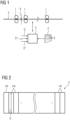
- a rolling mill comprises a number of rolling stands 1. In a minimal configuration, only a single rolling stand 1 is present. As a rule, as shown in FIG 1 several rolling stands 1 are present.
- a rolling stock 2 is rolled.
- the rolling stock 2 usually passes through the rolling stands 1 sequentially, i.e. not reversing.
- the rolling stock 2 is according to FIG 2 a flat rolled metal product, for example, a metal strip or a longer or shorter section of a metal strip.
- the rolled product 2 has a rolled product width b.
- the material of the rolled product 2 can be, for example, steel or aluminum.
- the rolling mill is controlled by a control device 3.
- the control device 3 is programmed with a control program 4.
- the control program 4 includes machine code 5, which can be directly executed by the control device 3.
- the programming of the control device 3 with the control program 4 or the execution of the machine code 5 by the control device 3 causes the control device 3 to execute a control method, which is explained in more detail below.
- the control method is explained below in connection with a single rolling stand 1 of the rolling mill.
- This rolling stand can be the frontmost rolling stand 1, the rearmost rolling stand 1, or a middle rolling stand 1 between the frontmost and rearmost rolling stands 1.
- the control method can also be applied to several of the rolling stands 1.
- the control method is explained below in connection with FIG 3 First, the structural design of the rolling stand 1 under consideration is explained, insofar as it is relevant in this case.
- the rolling stand 1 has work rolls 6.
- the rolling stock 2 is rolled between the work rolls 6.
- the work rolls 6 are mounted in chocks 7.
- the rolling stand 1 has (at least) one actuator 8, which acts on the chocks 7 and by whose control a roll gap profile can be adjusted exclusively over the entire barrel width - i.e. not just locally.
- FIG 3 There are even two such actuators 8a, 8b.
- One actuator 8a is a bending device by means of which the chocks 7 and, with them, the rolls 6, can be pressed apart.
- the other actuator 8b is a sliding device by means of which the chocks 7 and, with them, the rolls 6, can be axially displaced in opposite directions to one another.
- actuators 8 are also known to those skilled in the art which have the aforementioned properties, i.e., which influence the roll gap profile across the entire barrel width of the work rolls 6 by acting on the chocks 7.
- the rolling stand 1 further comprises a cooling device 9.
- the work rolls 6 are cooled by means of the cooling device 9.
- the cooling device 9 is preferably designed such that the rolls 6 are cooled location-dependently over the barrel length by means of the cooling device 9.
- the cooling device 9 comprises a plurality of individually controllable actuating devices 10.
- an individually controllable valve 11 and/or an individually controllable pump 12 can be arranged upstream of the actuating devices 10.
- the actuating devices 10 generally act on the rolls 6 by applying a liquid cooling medium 13 to the rolls 6.
- the liquid cooling medium 13 is generally water or at least contains water as its main component.
- other configurations of the actuating devices 10 are also conceivable.
- the knitting devices 10 can each act locally on a single section of the rollers 6, viewed along the bale length.
- multiple knitting devices 10 it is also possible for multiple knitting devices 10 to be present and for the cooling effect of the knitting devices 10 to extend over the entire bale length, but for the functional progression of the cooling effect to be different from one knitting device 10 to the next.
- One such configuration is, for example, the applicant's aforementioned Dynamic Work Roll Cooling.
- the control device 3 carries out the following control procedure:
- a step S1 the control device 3 receives a time profile of rolling stock data D for a rolling period T1.
- the rolling period T1 is according to FIG 5 the period of time - in the future - during which the rolling stock 2 is to be rolled in the rolling stand 1.
- the respective rolling stock data D relate to the condition of the corresponding section 14i immediately before the rolling of the corresponding section 14i in the rolling stand 1.
- the rolling stock data D can include, for example, the rolling stock width b, the thickness d, the temperature, the material strength, the contour and more of the corresponding section 14i. They can be specified individually for the individual sections 14i or uniformly for all sections 14i.
- the control device 3 receives roll stand data D' of the roll stand 1.
- the roll stand data D' can, for example, be specified to the control device 3 or determined by the control device 3 itself.
- the roll stand data D' of a respective time t1 of the rolling period T1 describe the state of the roll stand 1 with which the roll stand 1 is to be operated at the respective time t1.
- the roll stand data D' can include the setting, the rolling force, the roll gap in the middle of the roll stand 1, the roll gap profile across the width of the roll stand 1, the rolling force, and others.
- the roll stand data D' also includes an actuator control x8.
- the actuator control x8 is the control of actuator 8.
- the control device 3 receives initial data D" of the rolling stand 1.
- the initial data D" relate to the beginning of the determination period T2. They describe a state of rolls 6 of the rolling stand 1 at the beginning of the determination period T2.
- the initial data D" of the rolling stand 1 can, in particular, comprise the thermal state of the rolls 6 at the beginning of a determination period T2.
- the initial data D" can, if necessary, additionally comprise a wear state of the work rolls 6.
- the determination period T2 comprises at least the rolling period T1. However, it can, according to FIG 5 additionally include an additional period T3 preceding the rolling period T1. In this case, the additional period T3 directly adjoins the rolling period T1.
- the additional period T3 can also include additional rolling breaks and additional rolling periods.
- the control device 3 sets up an optimization problem.
- the optimization problem uses the rolling stock data D of the rolling stock 2 and the roll stand data D' of the roll stand 1 during the rolling period T1 and the initial data D" of the roll stand 1 at the beginning of the determination period T2 as input variables.
- the optimization problem also includes the temporal profile of the control of the cooling device 9 as a variable to be determined.
- the control of the cooling device 9 is referred to below as the cooling control and is provided with the reference symbol x9.
- the temporal profile of the cooling control x9 is set by the control device 3 for the determination period T2.
- the cost function for each time point ti can include the deviation of the resulting contour of the corresponding section 14i after rolling in the rolling mill.
- the influence of the cooling control x9 on the final product, i.e., the rolled stock 2 after rolling of the rolled stock 2 in all rolling stands 1 of the rolling mill is considered.
- the optimization objective is that the sections 14i of the rolled stock 2 have a predetermined target contour after rolling in the rolling mill (if possible).
- the cost function for the times ti can include the deviation of the resulting contour of the corresponding section 14i after rolling in the rolling stand 1.
- the influence of the cooling control x9 on an intermediate product, i.e., the rolling stock 2 immediately after rolling in the rolling stand 1, is considered.
- the optimization objective includes ensuring that the sections 14i of the rolling stock 2 have a predetermined target contour after rolling in the rolling stand 1 (if possible).
- the flatness of the rolled stock 2 can also be considered alternatively or in addition to the contour.
- the individual criteria are included in the cost function. Typically, they are each included as summands.
- the individual summands can be weighted with a respective weighting factor. It is possible for the cost function to contain only a single summand. In this case, the weighting factor can be omitted.
- step S5 control device 3 solves the optimization problem applied in step S4. It thereby determines the temporal progression of the cooling control x9.
- the optimization problem is solved in step S5 in such a way that the optimization goal is achieved as effectively as possible. Accordingly, control device 3 determines the temporal progression of the cooling control x9.
- Models can be used that are typically used in the context of pass schedule calculations for rolling mills. For example, there are also models that not only determine and consider the so-called thermal crown of rolls 6, but also calculate the wear occurring on rolls 6 of roll stand 1. In this case, the optimizer can consider the wear when determining the cooling control x9.
- a step S6 the control device 3 controls the cooling device 9 according to the determined cooling control x9.
- the cooling device 9 is controlled during the entire determination period T2.
- step S6 Due to the fact that in step S6, the cooling device 9 is to be controlled according to the cooling control x9 determined in step S5, steps S1 to S5 must be executed before the start of the determination period T2. In particular, step S5 must also be completed.
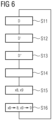
- FIG 6 shows a modification of the approach of FIG 4 .
- FIG 6 comprises steps S11 to S16.
- the rolling stand 1 includes the actuator 8.
- step S11 the control device 3 receives the time profile of rolling stock data D for the rolling period T1.
- step S12 the roll stand data D' are made known to the control device 3.
- step S13 the initial data D" are made known to the control device 3. Steps S11 to S13 correspond to steps S1 to S3 of FIG 4 . It is important, however, that the rolling stand data D does not include the actuator control x8.
- step S14 the control device 3 sets up an optimization problem analogously to step S4.
- the optimization problem uses the rolling stock data D of the rolling stock 2 and the rolling stand data D' of the rolling stock 1 during the rolling period T1 and the initial data D" of the rolling stand 1 at the beginning of the determination period T2 as input variables.
- the optimization problem does not only use the time profile as a variable to be determined.
- the control of the cooling device 9. Rather, the optimization problem also includes the actuator control x8 during the determination period T2 as a variable to be determined. The optimization problem is thus designed as a unified optimization problem.
- step S15 the control device 3 solves the uniform optimization problem set in step S14.
- the approach of step S15 corresponds to step S5 of FIG 4
- step S15 the control device 3 determines not only the time profile of the cooling control x9, but also the time profile of the actuator control x8.
- the optimization problem is solved in step S15 analogously to step S5 in such a way that the optimization goal is achieved as effectively as possible. Accordingly, the control device 3 determines the time profile of the cooling control x9 and the time profile of the actuator control x8.
- step S16 the control device 3 controls the cooling device 9 according to the determined cooling control x9.
- the cooling device 9 is controlled during the entire determination period T2.
- step S16 the control device 3 controls the actuator 8 at least during the rolling period T1 based on the determined actuator control x8.
- the control of the actuator 8 during the additional period T3 may be irrelevant if the rolling stock 2 is not rolled in the rolling stand 1 during the additional period.
- the predetermined optimization objective includes keeping the actuator 8 within a predetermined sub-range of its possible control range, i.e., the actuator control x8 moves within a predetermined sub-range, so that a sufficient control reserve remains to compensate for disturbances.
- the distance that the actuator 8 has from its minimum and/or maximum control i.e., the distance from the control limits of the actuator 8
- the optimization objective also includes keeping the actuator 8 within a predetermined (usually middle) sub-range of its possible control range.
- the optimization objective may include maintaining the actuator 8 within a predetermined (usually average) to maintain a subrange of its possible control range.
- the inequality constraints are generally specified alternatively, but in exceptional cases also in addition to considering the distance of the control x8 of actuator 8 from its minimum and/or maximum control in the cost function.
- a maximum cooling effect is not exceeded. This can ensure, for example, that the permissible control limits of the active devices 10 are adhered to. Alternatively or additionally, for the same purpose, it can also be specified that a maximum cooling effect is not exceeded across the entire active devices 10. This allows, for example, in the case of individually controlled valves 11 fed by a common pump 12, a maximum flow rate of the pump 12 to be taken into account.
- the present invention has many advantages.
- superior control of the rolling stand 1 can be achieved.
Landscapes
- Engineering & Computer Science (AREA)
- Mechanical Engineering (AREA)
- Control Of Metal Rolling (AREA)
Priority Applications (2)
| Application Number | Priority Date | Filing Date | Title |
|---|---|---|---|
| EP23218669.2A EP4574288A1 (fr) | 2023-12-20 | 2023-12-20 | Réglage prédictif de modèle de la bombé thermique d'un cylindre d'une cage de laminoir |
| PCT/EP2024/087155 WO2025132615A1 (fr) | 2023-12-20 | 2024-12-18 | Réglage prédictif par modèle du bombage thermique d'un rouleau d'une cage de laminage |
Applications Claiming Priority (1)
| Application Number | Priority Date | Filing Date | Title |
|---|---|---|---|
| EP23218669.2A EP4574288A1 (fr) | 2023-12-20 | 2023-12-20 | Réglage prédictif de modèle de la bombé thermique d'un cylindre d'une cage de laminoir |
Publications (1)
| Publication Number | Publication Date |
|---|---|
| EP4574288A1 true EP4574288A1 (fr) | 2025-06-25 |
Family
ID=89224487
Family Applications (1)
| Application Number | Title | Priority Date | Filing Date |
|---|---|---|---|
| EP23218669.2A Pending EP4574288A1 (fr) | 2023-12-20 | 2023-12-20 | Réglage prédictif de modèle de la bombé thermique d'un cylindre d'une cage de laminoir |
Country Status (2)
| Country | Link |
|---|---|
| EP (1) | EP4574288A1 (fr) |
| WO (1) | WO2025132615A1 (fr) |
Citations (6)
| Publication number | Priority date | Publication date | Assignee | Title |
|---|---|---|---|---|
| DE2911621A1 (de) | 1978-03-31 | 1979-10-04 | Loewy Robertson Eng Co Ltd | Verfahren zum betreiben eines walzwerks zur erzeugung von metallbaendern |
| EP0063605A1 (fr) | 1980-10-30 | 1982-11-03 | Mitsubishi Denki Kabushiki Kaisha | Systeme de controle de la forme d'une bande |
| EP0591291B1 (fr) * | 1991-06-28 | 1995-11-08 | Siemens Aktiengesellschaft | Regulation de la fabrication de feuillards lamines a chaud au moyen de laminoirs a chaud a cages multiples |
| US20060156778A1 (en) | 2005-01-20 | 2006-07-20 | Ondrovic Jay J | Method and apparatus for controlling strip shape in hot rolling mills |
| KR20160142956A (ko) | 2015-06-03 | 2016-12-14 | 동국제강주식회사 | 열간압연용 압연롤 냉각장치 및 압연롤 냉각수량 제어 방법 |
| EP3691806B1 (fr) * | 2017-10-02 | 2021-10-20 | Primetals Technologies Germany GmbH | Dispositif de réglage de planéité doté d'un dispositif d'optimisation |
-
2023
- 2023-12-20 EP EP23218669.2A patent/EP4574288A1/fr active Pending
-
2024
- 2024-12-18 WO PCT/EP2024/087155 patent/WO2025132615A1/fr active Pending
Patent Citations (6)
| Publication number | Priority date | Publication date | Assignee | Title |
|---|---|---|---|---|
| DE2911621A1 (de) | 1978-03-31 | 1979-10-04 | Loewy Robertson Eng Co Ltd | Verfahren zum betreiben eines walzwerks zur erzeugung von metallbaendern |
| EP0063605A1 (fr) | 1980-10-30 | 1982-11-03 | Mitsubishi Denki Kabushiki Kaisha | Systeme de controle de la forme d'une bande |
| EP0591291B1 (fr) * | 1991-06-28 | 1995-11-08 | Siemens Aktiengesellschaft | Regulation de la fabrication de feuillards lamines a chaud au moyen de laminoirs a chaud a cages multiples |
| US20060156778A1 (en) | 2005-01-20 | 2006-07-20 | Ondrovic Jay J | Method and apparatus for controlling strip shape in hot rolling mills |
| KR20160142956A (ko) | 2015-06-03 | 2016-12-14 | 동국제강주식회사 | 열간압연용 압연롤 냉각장치 및 압연롤 냉각수량 제어 방법 |
| EP3691806B1 (fr) * | 2017-10-02 | 2021-10-20 | Primetals Technologies Germany GmbH | Dispositif de réglage de planéité doté d'un dispositif d'optimisation |
Also Published As
| Publication number | Publication date |
|---|---|
| WO2025132615A1 (fr) | 2025-06-26 |
Similar Documents
| Publication | Publication Date | Title |
|---|---|---|
| EP1624982B2 (fr) | Procede de regulation de la temperature d'une bande metallique, en particulier dans un train finisseur pour le laminage a chaud de bandes metalliques | |
| EP2691188B1 (fr) | Procédé permettant de faire fonctionner un train de laminoir | |
| EP0121148B1 (fr) | Procédé pour la fabrication de feuillard à chaud avec section et planéité de bande de haute qualité | |
| EP2527053A1 (fr) | Procédé de commande pour une voie de laminage | |
| DE3028368C2 (fr) | ||
| EP3691806B1 (fr) | Dispositif de réglage de planéité doté d'un dispositif d'optimisation | |
| EP2293889B1 (fr) | Train de laminage continental doté d'intégrations et/ou de détachements de cages de laminoir en fonctionnement continu | |
| DE102014215397B4 (de) | Bandlageregelung mit optimierter Reglerauslegung | |
| DE3240602C2 (fr) | ||
| EP3231522B1 (fr) | Controle robuste de tension de bande | |
| EP4061552B1 (fr) | Procédé, dipositif de contrôle et laminoir pour le réglage d'une température de sortie d'une bande métallique quittant un train de laminage | |
| EP1173295A1 (fr) | Procede de laminage d'un feuillard metallique et dispositif de laminage y relatif | |
| DE102004005011B4 (de) | Regelverfahren und Regler für ein Walzgerüst | |
| WO2025132615A1 (fr) | Réglage prédictif par modèle du bombage thermique d'un rouleau d'une cage de laminage | |
| EP4103339B1 (fr) | Détermination de la sensibilité d'une grandeur cible d'une matière à laminer pour un paramètre de fonctionnement d'un train de laminage à chaud | |
| WO2020193099A1 (fr) | Prévention de la formation d'ondes lors du laminage de bandes métalliques | |
| DE3401894A1 (de) | Verfahren zum herstellen von walzband mit hoher bandprofil- und bandplanheitsguete | |
| EP2353742A1 (fr) | Laminage à chaud destiné au laminage de bande de chaleur, procédé de fonctionnement d'un laminage à chaud destiné au laminage de bande de chaleur, dispositif de commande et/ou de réglage | |
| EP2459329B1 (fr) | Procédé de commande et/ou de réglage d'une position d'une bande métallique passant dans une chaîne de laminage, dispositif de commande et/ou de réglage et chaîne de laminage | |
| DE10159608B4 (de) | Walzverfahren für ein Band mit einer Schweißnaht | |
| DE10321791A1 (de) | Verfahren zur Regelung der Temperatur eines Metallbandes, insbesondere in einer Fertigstraße zum Walzen von Metall-Warmband | |
| EP4277756B1 (fr) | Laminage à minimisation de la baisse de la force de flexion lors de la passe | |
| EP4442379B1 (fr) | Procédé de fonctionnement d'une installation de laminage continu à cage de compression | |
| EP3795267B1 (fr) | Procédé de fonctionnement d'une cage de laminoir | |
| AT408074B (de) | Verfahren und vorrichtung zur durchführung des stichplanwechsels während des walzens in einer mehrgerüstigen warmbandstrasse |
Legal Events
| Date | Code | Title | Description |
|---|---|---|---|
| PUAI | Public reference made under article 153(3) epc to a published international application that has entered the european phase |
Free format text: ORIGINAL CODE: 0009012 |
|
| STAA | Information on the status of an ep patent application or granted ep patent |
Free format text: STATUS: THE APPLICATION HAS BEEN PUBLISHED |
|
| AK | Designated contracting states |
Kind code of ref document: A1 Designated state(s): AL AT BE BG CH CY CZ DE DK EE ES FI FR GB GR HR HU IE IS IT LI LT LU LV MC ME MK MT NL NO PL PT RO RS SE SI SK SM TR |
|
| STAA | Information on the status of an ep patent application or granted ep patent |
Free format text: STATUS: REQUEST FOR EXAMINATION WAS MADE |
|
| 17P | Request for examination filed |
Effective date: 20260102 |