EP4574312A1 - Verfahren zum bereitstellen von steuerdaten zur herstellung eines werkstücks mittels einer laserpulverbettfusionsvorrichtung, steuereinheit, computerprogramm und speichermedium - Google Patents
Verfahren zum bereitstellen von steuerdaten zur herstellung eines werkstücks mittels einer laserpulverbettfusionsvorrichtung, steuereinheit, computerprogramm und speichermedium Download PDFInfo
- Publication number
- EP4574312A1 EP4574312A1 EP23219225.2A EP23219225A EP4574312A1 EP 4574312 A1 EP4574312 A1 EP 4574312A1 EP 23219225 A EP23219225 A EP 23219225A EP 4574312 A1 EP4574312 A1 EP 4574312A1
- Authority
- EP
- European Patent Office
- Prior art keywords
- exposure
- vector
- workpiece
- orientation
- region
- Prior art date
- Legal status (The legal status is an assumption and is not a legal conclusion. Google has not performed a legal analysis and makes no representation as to the accuracy of the status listed.)
- Pending
Links
Images


Classifications
-
- B—PERFORMING OPERATIONS; TRANSPORTING
- B33—ADDITIVE MANUFACTURING TECHNOLOGY
- B33Y—ADDITIVE MANUFACTURING, i.e. MANUFACTURING OF THREE-DIMENSIONAL [3D] OBJECTS BY ADDITIVE DEPOSITION, ADDITIVE AGGLOMERATION OR ADDITIVE LAYERING, e.g. BY 3D PRINTING, STEREOLITHOGRAPHY OR SELECTIVE LASER SINTERING
- B33Y50/00—Data acquisition or data processing for additive manufacturing
- B33Y50/02—Data acquisition or data processing for additive manufacturing for controlling or regulating additive manufacturing processes
-
- B—PERFORMING OPERATIONS; TRANSPORTING
- B22—CASTING; POWDER METALLURGY
- B22F—WORKING METALLIC POWDER; MANUFACTURE OF ARTICLES FROM METALLIC POWDER; MAKING METALLIC POWDER; APPARATUS OR DEVICES SPECIALLY ADAPTED FOR METALLIC POWDER
- B22F10/00—Additive manufacturing of workpieces or articles from metallic powder
- B22F10/20—Direct sintering or melting
- B22F10/28—Powder bed fusion, e.g. selective laser melting [SLM] or electron beam melting [EBM]
-
- B—PERFORMING OPERATIONS; TRANSPORTING
- B22—CASTING; POWDER METALLURGY
- B22F—WORKING METALLIC POWDER; MANUFACTURE OF ARTICLES FROM METALLIC POWDER; MAKING METALLIC POWDER; APPARATUS OR DEVICES SPECIALLY ADAPTED FOR METALLIC POWDER
- B22F10/00—Additive manufacturing of workpieces or articles from metallic powder
- B22F10/80—Data acquisition or data processing
-
- B—PERFORMING OPERATIONS; TRANSPORTING
- B22—CASTING; POWDER METALLURGY
- B22F—WORKING METALLIC POWDER; MANUFACTURE OF ARTICLES FROM METALLIC POWDER; MAKING METALLIC POWDER; APPARATUS OR DEVICES SPECIALLY ADAPTED FOR METALLIC POWDER
- B22F10/00—Additive manufacturing of workpieces or articles from metallic powder
- B22F10/80—Data acquisition or data processing
- B22F10/85—Data acquisition or data processing for controlling or regulating additive manufacturing processes
-
- B—PERFORMING OPERATIONS; TRANSPORTING
- B29—WORKING OF PLASTICS; WORKING OF SUBSTANCES IN A PLASTIC STATE IN GENERAL
- B29C—SHAPING OR JOINING OF PLASTICS; SHAPING OF MATERIAL IN A PLASTIC STATE, NOT OTHERWISE PROVIDED FOR; AFTER-TREATMENT OF THE SHAPED PRODUCTS, e.g. REPAIRING
- B29C64/00—Additive manufacturing, i.e. manufacturing of three-dimensional [3D] objects by additive deposition, additive agglomeration or additive layering, e.g. by 3D printing, stereolithography or selective laser sintering
- B29C64/10—Processes of additive manufacturing
- B29C64/141—Processes of additive manufacturing using only solid materials
- B29C64/153—Processes of additive manufacturing using only solid materials using layers of powder being selectively joined, e.g. by selective laser sintering or melting
-
- B—PERFORMING OPERATIONS; TRANSPORTING
- B29—WORKING OF PLASTICS; WORKING OF SUBSTANCES IN A PLASTIC STATE IN GENERAL
- B29C—SHAPING OR JOINING OF PLASTICS; SHAPING OF MATERIAL IN A PLASTIC STATE, NOT OTHERWISE PROVIDED FOR; AFTER-TREATMENT OF THE SHAPED PRODUCTS, e.g. REPAIRING
- B29C64/00—Additive manufacturing, i.e. manufacturing of three-dimensional [3D] objects by additive deposition, additive agglomeration or additive layering, e.g. by 3D printing, stereolithography or selective laser sintering
- B29C64/30—Auxiliary operations or equipment
- B29C64/386—Data acquisition or data processing for additive manufacturing
- B29C64/393—Data acquisition or data processing for additive manufacturing for controlling or regulating additive manufacturing processes
-
- B—PERFORMING OPERATIONS; TRANSPORTING
- B33—ADDITIVE MANUFACTURING TECHNOLOGY
- B33Y—ADDITIVE MANUFACTURING, i.e. MANUFACTURING OF THREE-DIMENSIONAL [3D] OBJECTS BY ADDITIVE DEPOSITION, ADDITIVE AGGLOMERATION OR ADDITIVE LAYERING, e.g. BY 3D PRINTING, STEREOLITHOGRAPHY OR SELECTIVE LASER SINTERING
- B33Y50/00—Data acquisition or data processing for additive manufacturing
-
- C—CHEMISTRY; METALLURGY
- C22—METALLURGY; FERROUS OR NON-FERROUS ALLOYS; TREATMENT OF ALLOYS OR NON-FERROUS METALS
- C22C—ALLOYS
- C22C1/00—Making non-ferrous alloys
- C22C1/04—Making non-ferrous alloys by powder metallurgy
- C22C1/0433—Nickel- or cobalt-based alloys
-
- G—PHYSICS
- G06—COMPUTING OR CALCULATING; COUNTING
- G06F—ELECTRIC DIGITAL DATA PROCESSING
- G06F30/00—Computer-aided design [CAD]
- G06F30/10—Geometric CAD
-
- G—PHYSICS
- G06—COMPUTING OR CALCULATING; COUNTING
- G06F—ELECTRIC DIGITAL DATA PROCESSING
- G06F30/00—Computer-aided design [CAD]
- G06F30/10—Geometric CAD
- G06F30/17—Mechanical parametric or variational design
-
- B—PERFORMING OPERATIONS; TRANSPORTING
- B22—CASTING; POWDER METALLURGY
- B22F—WORKING METALLIC POWDER; MANUFACTURE OF ARTICLES FROM METALLIC POWDER; MAKING METALLIC POWDER; APPARATUS OR DEVICES SPECIALLY ADAPTED FOR METALLIC POWDER
- B22F10/00—Additive manufacturing of workpieces or articles from metallic powder
- B22F10/30—Process control
- B22F10/36—Process control of energy beam parameters
- B22F10/366—Scanning parameters, e.g. hatch distance or scanning strategy
-
- B—PERFORMING OPERATIONS; TRANSPORTING
- B22—CASTING; POWDER METALLURGY
- B22F—WORKING METALLIC POWDER; MANUFACTURE OF ARTICLES FROM METALLIC POWDER; MAKING METALLIC POWDER; APPARATUS OR DEVICES SPECIALLY ADAPTED FOR METALLIC POWDER
- B22F10/00—Additive manufacturing of workpieces or articles from metallic powder
- B22F10/30—Process control
- B22F10/38—Process control to achieve specific product aspects, e.g. surface smoothness, density, porosity or hollow structures
-
- G—PHYSICS
- G06—COMPUTING OR CALCULATING; COUNTING
- G06F—ELECTRIC DIGITAL DATA PROCESSING
- G06F2113/00—Details relating to the application field
- G06F2113/10—Additive manufacturing, e.g. three-dimensional [3D] printing
-
- Y—GENERAL TAGGING OF NEW TECHNOLOGICAL DEVELOPMENTS; GENERAL TAGGING OF CROSS-SECTIONAL TECHNOLOGIES SPANNING OVER SEVERAL SECTIONS OF THE IPC; TECHNICAL SUBJECTS COVERED BY FORMER USPC CROSS-REFERENCE ART COLLECTIONS [XRACs] AND DIGESTS
- Y02—TECHNOLOGIES OR APPLICATIONS FOR MITIGATION OR ADAPTATION AGAINST CLIMATE CHANGE
- Y02P—CLIMATE CHANGE MITIGATION TECHNOLOGIES IN THE PRODUCTION OR PROCESSING OF GOODS
- Y02P10/00—Technologies related to metal processing
- Y02P10/25—Process efficiency
Definitions
- the present invention relates to a method of providing control data for manufacturing a workpiece by a laser powder bed fusion device, and a method to operate a laser powder bed fusion device to manufacture a workpiece. Furthermore the present invention relates to a corresponding control unit and a corresponding laser powder bed fusion device. Additionally, the present invention relates to a respective computer program and a respective storage medium.
- LPBF Laser powder bed fusion
- a first aspect of the present invention is related to a method of providing control data for manufacturing of a workpiece by a laser powder bed fusion device.
- the method comprises the following steps performed by a control unit.
- the control data may comprise instructions for a laser powder bed fusion device to manufacture the workpiece.
- a first step of the method comprises a reception of the volume model of the workpiece by the control unit.
- the volume model describes a volume of material of the workpiece to be manufactured by the laser powder bed fusion device.
- the volume model of the workpiece may comprise a 3-D model of the workpiece and material parameters of the workpiece.
- the volume model may be a CAD file for example.
- the method comprises a step of evaluating a stack of consecutive layers for manufacturing the workpiece based on the volume model.
- the control unit determines the respective layers for manufacturing the workpiece and aligns them in a stack.
- the method comprises a step of evaluating for each of the layers a local material depth function describing a local material depth of the volume module below the respective layer by the control unit.
- the local material depth is limited by a predefined maximal depth.
- the control unit evaluates for each of the layers the material of the volume model below the respective layer.
- the control unit determines the local material depth of the volume model below the layer.
- the local material depth is limited to the predefined maximal depth. In other words, the control unit determines the local material depth under the respective layer up to the predefined maximal depth. Therefore, the control unit ignores a portion of the material depth larger than the predefined maximal depth.
- the control unit evaluates the local material depth function, wherein the local material depth function assigns the respective local material depth to the respective position within the layer.
- the method comprises a step of dividing the respective layers into continuous regions of predefined categories based on the local modified mass integral values.
- the local modified mass integral value may change within the respective layers.
- the respective layers are divided into the continuous regions.
- the regions are attributed to predefined categories.
- the categories are defined by predefined local mass integral value ranges.
- the categories are associated with respective manufacturing parameters for manufacturing the respective regions.
- the method comprises a step of generating control data to control the laser powder bed fusion device to manufacture the workpiece by the control unit.
- the invention has the advantage that the control data assign respective manufacturing parameters to regions of the respective workpiece depending on an overlap of the workpiece in the regions, described by the local modified mass integral values. Therefore, the method allows overhanging regions to be taken into account in the manufacturing of the workpiece.
- the method comprises the following steps performed by the control unit.
- the method comprises a step of evaluating for each region of at least one first category of the predefined categories a respective exposure vector orientation according to a predefined orientation evaluation method.
- a predefined orientation evaluation method In other words to manufacture the workpiece, an energy beam has to be guided along the respective exposure vectors within the respective layers.
- Each region of the at least one of the predefined categories may comprise respective exposure vectors oriented in the same exposure vector orientation within the respective region.
- the orientation of the exposure vectors within the respective region may influence a quality of the material of the workpiece within the respective region. Therefore, it is an object of the orientation evaluation method to improve the quality of the respective region by investigating the exposure vector orientation for the respective region.
- the orientation evaluation method may be performed for each region of the first category.
- the orientation evaluation method may also be performed for each region of one or more other of the categories.
- the orientation evaluation method comprises a calculation for each candidate exposure vector orientation of the respective region an average absolute difference value describing an average of absolute difference values of the exposure vectors in the region, oriented in the respective candidate exposure vector orientation.
- the candidate exposure vector orientations may be predefined or investigated.
- the control unit draws the exposure vectors of the respective region for each of the candidate exposure vector orientation.
- the control unit evaluates for each of the exposure vectors the respective mass integral value at the start point of the respective exposure vector and a mass integral value at the end point of the respective exposure vector.
- control unit calculates the absolute difference value describing the absolute difference between the mass integral value at the start point of the respective exposure vector and the endpoint of the respective exposure vector. In a next step, the control unit determines the average absolute difference value describing the average of the absolute difference values of the exposure vectors in the region of the respective candidate exposure vector orientation. In a next step, the control unit compares the average absolute difference values evaluated for the respective candidate exposure vector orientations of the region.
- a next step comprises a selecting of the respective exposure vector orientation for the respective region out of the candidate exposure vector orientations depending on the average absolute difference values calculated for the respective candidate exposure vector orientations.
- the exposure vector orientation for the respective region is selected as a function of the average absolute difference value. The selection may be performed by the control unit by choosing the candidate exposure vector orientation giving the highest absolute difference value.
- the orientation evaluation method comprises a step of evaluating the respective exposure vector orientation of an underlying region of an underlying layer of the region.
- the control unit may evaluate the respective exposure vector orientations of the regions layer by layer. Therefore, the region in a respective layer may be above an underlying region in an underlying layer.
- a quality of the workpiece may depend on a relation between the exposure vector orientation of the underlying layer and the layer above the underlying layer. In particular, a uniform orientation of the exposure vectors of superimposed regions may lead to a decrease in stability.
- the respective exposure vector orientation of the respective region above the underlying region is selected as a function of the exposure vector orientation of the underlying region.
- control unit limits the candidate exposure vector orientations of the respective region to those having an orientation difference above a predefined orientation difference value with respect to the respective exposure vector orientation of the underlying region.
- a predefined orientation difference value may be 45°.
- the orientation evaluation method comprises a step of calculating for each region of at least a second category a maximum value of an onset exposure vector of an exposure sequence.
- the maximum value gives a maximum of the mass integral value at the start point of the respective onset exposure vector and the mass integral value at the end point of the respective onset exposure vector.
- the exposure sequence sets the chronological order in which the exposure vectors are illuminated during manufacturing. The exposure sequence starts with the onset exposure vector.
- the method comprises a step of performing for each region having the onset exposure vector with a maximum value below a threshold value a predefined reordering algorithm for evaluating a new exposure sequence.
- the reordering algorithm comprises a step of calculating the maximum values of the exposure vectors of the exposure sequence.
- a first of the respective exposure vectors according to the exposure sequence is defined as a new onset exposure vector of the new exposure sequence.
- the exposure vector of the highest maximum value is defined as the new onset exposure vector of the new exposure sequence.
- the method comprises a step of evaluating for each of the exposure vectors of the region of at least a third category of the categories, the respective mass integral value along the respective exposure vector.
- the method comprises a step of evaluating manufacturing parameters along the exposure vectors depending on the respective mass integral value along the respective exposure vector.
- the step of evaluating manufacturing parameters along the exposure vectors may also be performed on exposure vectors of the regions of the second category of the categories.
- the method comprises a step of removing contours of the regions of at least a fourth category of the categories from the layers. In other words, the contours of the regions of at least the fourth category are deleted. It may not be possible to produce the contours of the regions in a stable manner. For that reason, the control data for the laser powder bed fusion device to manufacture the respective regions are generated for the respective region without a part of the region comprising the contour.
- the contour may comprise grid points of the region of a local modified mass integral value below a predefined threshold.
- As second aspect of the present invention relates to a method to operate a laser powder bed fusion device to manufacture a workpiece.
- the method to operate a laser powder bed fusion device comprises steps of a method of providing control data for manufacturing a workpiece by a laser powder bed fusion device according to the first aspect of the present invention.
- a third aspect of the present invention relates to a control unit.
- the control unit is configured to perform a method of providing control data for manufacturing a workpiece by a laser powder bed fusion device according to the first aspect of the present invention and/or to perform a method for providing the control data to the laser powder bed fusion device to control the laser powder bed fusion device to manufacture the workpiece according to the second aspect of the present invention.
- a third step S3, a fourth step S4 and a fifth step S5 may relate to a separation of the layers 6 into regions 9 of different modified mass integral values.
- the next steps may also refer to FIG 3 .
- the fourth step S4 of the method may comprise an evaluation of a function describing a local modified mass integral value within a respective one of the layers 6.
- the local modified mass integral value may describe a local proportion of a predefined reference volume 7 within a local depth volume of the local material depth.
- the local modified mass integral value may be calculated for grid points 12 of a regular grid within the respective layers 6.
- the control unit 3 may generate for each of the layers 6 the respective regular grid.
- the respective regular grid may comprise the grid points 12 of a regular grid distance of 0.1 mm.
- the control unit 3 may calculate the local modified mass integral value for each of the grid points 12 of the regular grid.
- an interior of the workpiece 1 may be covered by the regular grid points 12.
- An example of one of the layers 6 for manufacturing the workpiece 1 part is shown in FIG 2 .
- a regular distance of 0.1 mm is chosen for the grid of the grid points 12.
- the modified mass integral may be evaluated.
- the modified mass integral is shift into the local material depth z depth .
- the local material depth value gives a distance of downwards material that contribute to the workpiece 1.
- the modified mass integral value may determine how much of the predefined reference volume 7 which may be a halfsphere of a predefined radius r int is enclosed in the model 4 in local depth z depth .
- the values of r int and z max may be chosen empirically.
- convolutional kernels in the local material depth z depth may be used as the predefined reference volume 7 besides the halfsphere described above.
- cylindrical or half-ellipsoidal forms are also well suited.
- the fifth step S5 of the method may comprise a division of the respective layers 6 into continuous regions 9 of predefined categories based on the local modified mass integral value within the respective layers 6.
- the categories are defined by predefined local modified mass integral value ranges. A stable manufacturing of the regions 9 may require manufacturing parameters adjusted to the local modified mass integral values. Therefore, the categories are assigned respective manufacturing parameters.
- the respective layer 6 may be divided into lateral regions 9. Each of the regions 9 may be assigned to a respective of the categories.
- the categories define the manufacturing parameters to manufacture the respective regions 9 by the laser powder bed fusion device 2.
- the category of the respective region 9 is selected based on the local modified mass integral values of the grid points 12 of the region 9.
- one or multiple threshold values ⁇ int of the modified mass integral values may be selected.
- the threshold values ⁇ int may define the ranges of the categories.
- the layers 6 of the workpiece 1 may then be separated into the regions 9 accordingly to the different ⁇ int values.
- FIG 4 shows an example of a separation of one of the layers 6 in two of the regions 9.
- One of the two regions 9 may comprise grid points 12 of local modified mass integral values above a threshold mInt depth > ⁇ int .
- the other of the two regions 9 may comprise grid points 12 of the local modified mass integral values below or equal to the threshold mInt depth ⁇ ⁇ int .
- the identified regions 9 may be assigned respective, different manufacturing parameters.
- the regions 9 with low mInt depth values correspond to low-pitched overhangs of the model 4.
- These regions 9 are typically assigned manufacturing parameters comprising a lower laser power in combination with a smaller hatch distance and/or shorter pauses between the exposition of the exposure vectors 10.
- a small overlap between the regions 9, for example 0.1 mm to 0.3 mm may be intended.
- Regions 9 of higher modified mass integral values may be exposed first, followed by the regions 9 with lower modified mass integral values.
- a sixth step S6 of the method may comprise a removing of contours of regions 9 of the at least a fourth category from the layers 6.
- the categories comprise a fourth category associated with grid points 12 having the local modified mass integral values below a predefined fourth threshold.
- the modified local mass integral values below the predefined fourth threshold may be too low to allow a stable manufacturing of the contours of the specific regions 9. Therefore, the respective regions 9 may be deleted.
- contours of the very low mass regions 9 below a predefined threshold may advised to be skipped in most cases.
- the steps S7 to S9 may be related to a choice of an optimal exposure vector 10 orientation for at least the regions 9 of a first category.
- the control unit 3 may evaluate for each region 9 of at least the first category the respective exposure vector 10 orientation according to a predefined orientation evaluation method.
- the regions 9 are manufactured by guiding an energy beam along the exposure vectors 10 within the regions 9.
- the exposure vectors 10 of the respective region 9 may be oriented in a respective exposure vector 10 orientation of the respective region 9.
- the exposure vector 10 orientation of the exposure vectors 10 of the respective region 9 may influence a quality of the respective region 9. Therefore, the exposure vector 10 orientations of the regions 9 of at least the first category may be evaluated using the predefined orientation evaluation method.
- the optimal exposure vectors 10 orientation may be evaluated.
- the region 9 may be hatched using a standard zig-zag exposure vector 10 technique according to the state of the art.
- An example of hatched region 9 is shown in FIG 5 .
- the candidate exposure vector 10 orientation whose average value a orient is maximal may be chosen as the exposure vector 10 orientation of the region 9. It means that with this exposure vector 10 orientation, a majority of the exposure vectors 10 start or end at points of a higher standard mass integral value.
- consecutive layer 6 regions 9 should have sufficiently different exposure vector 10 orientations to average out orientation dependent effects as e.g., surface corrugation. Therefore, if the optimal exposure vector 10 orientation may differs by less than 45° from the previous layer 6 region 9, than the candidate exposure vector 10 orientation with a maximal a orient value may be chosen only from candidate exposure vector 10 orientations that are different enough from the exposure vector 10 orientation of the region 9 of the previous layer 6.
- the eighth step S8 of the method may comprise a calculation for each candidate exposure vector 10 orientation of the respective region 9 an average absolute difference value describing an average of an absolute difference value of the exposure vectors 10 in the region 9 oriented in the respective candidate exposure vector 10 orientation.
- a group of candidate exposure vector 10 orientations of the respective region 9 may depend on the exposure vector 10 orientation of one or more regions 9 below the respective region 9. In other words, only candidate exposure vector 10 orientations may be used, having an orientation difference above a predefined difference value with respect to the exposure vector 10 orientation of the region 9 below the respective region 9.
- the control unit 3 may calculate the respective average absolute difference value for each of the candidate exposure vector 10 orientations.
- the control unit 3 may arrange the exposure vectors 10 of the respective candidate exposure vector 10 orientation in the respective region 9.
- Each of the candidate exposure vectors 10 may have a start point and a respective end point.
- the control unit 3 may calculate the modified mass integral value for the start point of the respective exposure vector 10 and the end point of the respective exposure vector 10.
- the control unit 3 may calculate the absolute difference value, defining the absolute difference between the modified mass integral value at the start point of the respective exposure vector 10 and the endpoint of the respective exposure vector 10.
- Each of the exposure vectors 10 may have a respective absolute difference value.
- the control unit 3 may calculate the average absolute difference value giving the average of the absolute difference values of the exposure vectors 10.
- the ninth step S9 of the method may comprise a selection of the respective exposure vector 10 orientation for the respective region 9 out of the candidate exposure vector 10 orientations depending on the average absolute difference values calculated for the respective candidate exposure vector 10 orientations.
- the control unit 3 may select the exposure vector 10 orientation having a biggest average absolute difference value as the exposure vector 10 orientation of the respective region 9.
- the steps S10 to S13 may relate to a resorting of the exposure vectors 10 in the regions 9 of at least a second category according to maximum mass integral values.
- a tenth step S10 of the method may comprise a calculation for each region 9 of at least a second category a maximum value of an onset exposure vector 10 of an exposure sequence.
- the maximum value gives a maximum of the mass integral value at the start point of the respective onset exposure vector 10 and the mass integral value at the end point of the respective onset exposure vector 10.
- the control unit 3 may generate an exposure sequence describing the sequence of the exposure vectors 10 during the manufacturing.
- the exposure sequence may be determined according to a standard method. However, the exposure sequence may be replaced by a new exposure sequence. A need to replace the exposure sequence with a new exposure sequence may depend on the maximum value of the onset exposure vector 10.
- An eleventh step S11 may comprise performing for each region 9 having an onset exposure vector 10 with the maximum value below a predefined threshold value, a predefined reordering algorithm for evaluating the new exposure sequence.
- control unit 3 may calculate the maximum values of the other exposure vectors 10 of the exposure sequence.
- control unit 3 may define a first of the respective exposure vectors 10 according to an order of the exposure sequence as a new onset exposure vector 10 of the new exposure sequence.
- control unit 3 may define the exposure vector 10 of the highest maximum value as the onset exposure vector 10 of the new exposure sequence.
- a reordering algorithm for exposure vectors 10 is introduced, since even with the optimal exposure vector 10 orientation and the exposure vectors 10 as described above, it may still happen that the exposure of a respective one of the exposure vectors 10 starts at an inappropriate point in the layer 6 with a very low modified mass integral value.
- the maximal value max mInt 0 ⁇ M v of the first exposure vector 10 is below a chosen threshold M v , then an attempt to find another exposure vector 10 for hatching start will be made.
- the exposure vectors 10 from the region 9 may be proved consecutively until a false condition for the exposure vector 10 of some index i new is found. If no exposure vector 10 with max mInt i ⁇ M v is found, then i new may chosen as the exposure vector 10 with max i max mInt i .
- the new onset exposure vector 10 i new may start the new hatch exposure vectors 10 order, defined by the exposure sequence. The following exposure vectors 10 i new + 1 , i new + 2, ... may be exposed in succession. And afterwards the exposure vectors 10 in reverse order i new - 1, i new - 2, ... may be exposed. Effectively, exposure vectors 10 with critically low start/end-point masses may be exposed in a decreasing mass order.
- the next steps may relate to a tuning of exposure parameters and/or vector 10 splitting according to the mass integral value along the respective exposure vector 10.
- the steps may serve to refine the laser powder bed fusion process parameter selection.
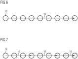
- a regular vector 10 grid may be applied to each of the exposure vectors 10, covering its beginning and end. Similar to the grid of grid points 12 a reasonable choice for the vector 10 grid step size may be 0.1 mm. An example is shown in FIG 6 .
- the standard mass integral values may be evaluated for each vector 10 grid point.
- One possible tuning of the exposure parameters is to assign a continuous function that reduces laser power according to the mass integral values.
- Another possibility is to split the respective exposure vector 10 into several vectors 10 according to sections of different mass integral thresholds.
- a fourteenth step S14 of the method may comprises an evaluation for each of the exposure vectors 10 of the region 9 of a third category the respective mass integral value along the respective exposure vector 10. Therefore the control unit 3 may arrange a regular vector 10 grid of vector grid points 13 along each of the exposure vectors 10.
- a fifteenth step S15 of the method comprises an evaluation of manufacturing parameters along the exposure vectors 10 depending on the respective mass integral value along the respective exposure vector 10.
- the control unit 3 may change the manufacturing parameters along the exposure vectors 10.
- a sixteenth step S16 of the method may comprise a generation of control data 11 to control the laser powder bed fusion device 2 to manufacture the workpiece 1.
- the control unit 3 may generate the control data 11 necessary to manufacture the workpiece 1 by the manufacture device.
- a seventeenth step S17 of the method may comprise a provision of the control data 11 to the laser powder bed fusion device 2 by the control unit 3 to control the laser powder bed fusion device 2 to manufacture of the workpiece 1.
- An eighteenth step S18 of the method may comprise a manufacturing of the workpiece 1 by the laser powder bed fusion device 2.
- overhang regions 9 of low angles may be manufactured without supports. Long overhangs of 17.5° can be built with Inconel 718 material. In comparison, standard techniques led to crash in the manufacturing.
- FIG 2 shows a schematic illustration of a model 4 of the workpiece separated into a stack 5 of layers 6.
- the stack 5 of layers 6 may be a sequence of layers 6 aligned in parallel and separated by appropriate distances.
- the figure shows one of the layers 6 which may be placed on top of other layers 6.
- a portion of the layer 6 within the model 4 may have a regular grid of grid points 12.
- the grid points 12 may be separated by a grid spacing.
- the control unit 3 may evaluate the respective modified mass integral value. The evaluation of the respective modified mass integral values is shown in FIG 3 .
- FIG 3 shows a schematic illustration of reference volume 7s.
- FIG 3 shows a cross section of the model 4.
- a depth of the model 4 below the layer 6 surface may increase in an x-direction. Therefore the two grid points 12 may have different local depths z depth giving the depth of the model 4 below the grid point.
- the local depth z depth may be limited to the maximum depth z max , as volume below the maximum depth z max may neglected.
- the reference volumes 7 may be half spheres, wherein each of the reference volumes 7 may have a centerpoint 8 below a respective one of the grid points 12 in the local depth z depth .
- the reference volumes 7 may have a radius r int around the centerpoint 8.
- FIG 4 shows a schematic illustration of regions 9 within a layer 6.
- the workpiece 1 may be separated into regions 9.
- the two regions 9 may correspond to different categories.
- the respective grid points 12 may be assigned to one of the two regions 9 depending on the respective modified mass integral values mInt depth .
- the workpiece 1 may be separated into two regions 9 by a threshold value ⁇ int of the modified mass integral value mInt depth , seperating the ranges of the two categories.
- FIG 4 shows an example of separation in the two regions 9 wherein grid points 12 of mInt depth > ⁇ int are assigned to one of the regions 9 and grid points 12 of mInt depth ⁇ _ ⁇ int to the other of the two regions 9.
- the region 9 with grid points 12 mInt depth ⁇ ⁇ int may be close to a border of the model 4.
- the lower modified mass integral values mInt depth of the region 9 may be associated with steep borders of the workpiece 1.
- the region 9 with the lower modified mass integral values mInt depth correspond to low-pitched overhangs.
- These regions 9 are typically assigned with lower laser power in combination with smaller hatch distance and/or pauses between exposure vectors 10. It may be intended to define a small overlap between the two regions 9 of 0.1 mm to 0.3 mm.
- FIG 5 shows a schematic illustration of exposure vectors 10 in a region
- FIG 5 shows the exposure vectors 10, also called hatch vectors 10, for the region 9 of FIG. 4 having the lower modified mass integral values mInt depth .
- FIG 6 shows a schematic illustration of vector grid points 13 along an exposure vector 10.
- the control unit 3 may arrange vector grid points 13 along each of the exposure vectors 10.
- the Control unit 3 may calculate the modified mass integral values mInt depth for each of the vector grid points 13.
- the control unit 3 may change manufacturing parameters along the exposure vector 10 as a function of the modified mass integral values mInt depth along the exposure vector 10.
- FIG 7 shows a schematic illustration of the vector 10 of FIG 6 divided in three vectors 10.
- the control unit 3 may divide the exposure vector 10 of FIG 6 into shorter exposure vectors 10, wherein each of the vectors 10 may comprise vector 10 grid points of a similar modified mass integral value mInt depth .
Landscapes
- Engineering & Computer Science (AREA)
- Chemical & Material Sciences (AREA)
- Materials Engineering (AREA)
- Physics & Mathematics (AREA)
- Manufacturing & Machinery (AREA)
- Geometry (AREA)
- Theoretical Computer Science (AREA)
- General Physics & Mathematics (AREA)
- Mechanical Engineering (AREA)
- Optics & Photonics (AREA)
- Pure & Applied Mathematics (AREA)
- Computational Mathematics (AREA)
- Mathematical Analysis (AREA)
- Mathematical Optimization (AREA)
- Computer Hardware Design (AREA)
- Evolutionary Computation (AREA)
- General Engineering & Computer Science (AREA)
- Plasma & Fusion (AREA)
- Organic Chemistry (AREA)
- Metallurgy (AREA)
Priority Applications (2)
| Application Number | Priority Date | Filing Date | Title |
|---|---|---|---|
| EP23219225.2A EP4574312A1 (de) | 2023-12-21 | 2023-12-21 | Verfahren zum bereitstellen von steuerdaten zur herstellung eines werkstücks mittels einer laserpulverbettfusionsvorrichtung, steuereinheit, computerprogramm und speichermedium |
| PCT/EP2024/082388 WO2025131462A1 (en) | 2023-12-21 | 2024-11-14 | Method of providing control data for manufacturing a workpiece by a laser powder bed fusion device, method to operate a laser powder bed fusion device, control unit, computer program and storage medium |
Applications Claiming Priority (1)
| Application Number | Priority Date | Filing Date | Title |
|---|---|---|---|
| EP23219225.2A EP4574312A1 (de) | 2023-12-21 | 2023-12-21 | Verfahren zum bereitstellen von steuerdaten zur herstellung eines werkstücks mittels einer laserpulverbettfusionsvorrichtung, steuereinheit, computerprogramm und speichermedium |
Publications (1)
| Publication Number | Publication Date |
|---|---|
| EP4574312A1 true EP4574312A1 (de) | 2025-06-25 |
Family
ID=89308021
Family Applications (1)
| Application Number | Title | Priority Date | Filing Date |
|---|---|---|---|
| EP23219225.2A Pending EP4574312A1 (de) | 2023-12-21 | 2023-12-21 | Verfahren zum bereitstellen von steuerdaten zur herstellung eines werkstücks mittels einer laserpulverbettfusionsvorrichtung, steuereinheit, computerprogramm und speichermedium |
Country Status (2)
| Country | Link |
|---|---|
| EP (1) | EP4574312A1 (de) |
| WO (1) | WO2025131462A1 (de) |
Citations (4)
| Publication number | Priority date | Publication date | Assignee | Title |
|---|---|---|---|---|
| EP3581297A1 (de) * | 2018-06-12 | 2019-12-18 | Siemens Aktiengesellschaft | Verfahren zum bestimmen von bauvorschriften für ein additives fertigungsverfahren, verfahren zum erstellen einer datenbank mit korrekturmassnahmen für die prozessführung eines additiven fertigungsverfahrens, speicherformat für bauanweisungen und computer-programmprodukt |
| US20200039145A1 (en) * | 2017-04-13 | 2020-02-06 | Siemens Aktiengesellschaft | Powder-Bed-Based Additive Manufacture of a Workpiece |
| WO2022123224A1 (en) * | 2020-12-07 | 2022-06-16 | Renishaw Plc | Powder bed fusion methods and related apparatus |
| WO2022223381A1 (en) * | 2021-04-19 | 2022-10-27 | SLM Solutions Group AG | Method of controlling an irradiation system, irradiation system, computer program product and apparatus for producing a three-dimensional work piece |
-
2023
- 2023-12-21 EP EP23219225.2A patent/EP4574312A1/de active Pending
-
2024
- 2024-11-14 WO PCT/EP2024/082388 patent/WO2025131462A1/en active Pending
Patent Citations (4)
| Publication number | Priority date | Publication date | Assignee | Title |
|---|---|---|---|---|
| US20200039145A1 (en) * | 2017-04-13 | 2020-02-06 | Siemens Aktiengesellschaft | Powder-Bed-Based Additive Manufacture of a Workpiece |
| EP3581297A1 (de) * | 2018-06-12 | 2019-12-18 | Siemens Aktiengesellschaft | Verfahren zum bestimmen von bauvorschriften für ein additives fertigungsverfahren, verfahren zum erstellen einer datenbank mit korrekturmassnahmen für die prozessführung eines additiven fertigungsverfahrens, speicherformat für bauanweisungen und computer-programmprodukt |
| WO2022123224A1 (en) * | 2020-12-07 | 2022-06-16 | Renishaw Plc | Powder bed fusion methods and related apparatus |
| WO2022223381A1 (en) * | 2021-04-19 | 2022-10-27 | SLM Solutions Group AG | Method of controlling an irradiation system, irradiation system, computer program product and apparatus for producing a three-dimensional work piece |
Non-Patent Citations (1)
| Title |
|---|
| GAYNOR ANDREW T ET AL: "Topology optimization considering overhang constraints: Eliminating sacrificial support material in additive manufacturing through design", STRUCTURAL AND MULTIDISCIPLINARY OPTIMIZATION, SPRINGER BERLIN HEIDELBERG, BERLIN/HEIDELBERG, vol. 54, no. 5, 13 September 2016 (2016-09-13), pages 1157 - 1172, XP036097795, ISSN: 1615-147X, [retrieved on 20160913], DOI: 10.1007/S00158-016-1551-X * |
Also Published As
| Publication number | Publication date |
|---|---|
| WO2025131462A1 (en) | 2025-06-26 |
Similar Documents
| Publication | Publication Date | Title |
|---|---|---|
| Tata et al. | Efficient slicing for layered manufacturing | |
| US6363298B1 (en) | Method and apparatus for generating tool paths | |
| CN110370646B (zh) | 3d打印方法、装置、电子设备及存储介质 | |
| CN110570038B (zh) | 一种不规则带缺陷板材矩形排样方法及装置 | |
| US20050015173A1 (en) | Rapid prototyping method and device using v-cad data | |
| CN102779147B (zh) | 用于导航设备的数据库、输出地形三维表示的方法以及产生数据库的方法 | |
| CN104331933B (zh) | 一种分层方向自适应快速选取方法 | |
| KR100892353B1 (ko) | 광조형 방법, 광조형 시스템 및 광조형 프로그램 | |
| CN115170580A (zh) | 板材加工控制方法、装置、计算机设备及存储介质 | |
| US20190325647A1 (en) | Singularity reduction in quadrilateral meshes | |
| EP4574312A1 (de) | Verfahren zum bereitstellen von steuerdaten zur herstellung eines werkstücks mittels einer laserpulverbettfusionsvorrichtung, steuereinheit, computerprogramm und speichermedium | |
| EP0240569A1 (de) | Verfahren zur bildung einer komposit-gekrümmten oberfläche | |
| CN104145223A (zh) | 加工程序生成装置、加工程序生成方法以及加工程序生成程序 | |
| JP3679110B2 (ja) | 板金加工用cad/camシステム,プログラム及びプログラムを記録した記録媒体 | |
| US20220410330A1 (en) | Incremental sheet forming systems and methods for forming structures having steep walls | |
| JP2004326205A (ja) | 物体加工のためのデータ生成方法及びプログラム並びに装置 | |
| WO2018044247A1 (en) | A computer implemented method for segmentation of a ship hull into small plates by a split-and-pack approach | |
| US4855926A (en) | Complex curved surface creation method | |
| US4855921A (en) | Complex curved surface creation method | |
| US7080329B1 (en) | Method and apparatus for identifying optimized via locations | |
| EP3901718B1 (de) | Mehrstufige inkrementale blattbildungssysteme und verfahren | |
| CN117236509A (zh) | 基于重叠分离的板材件排样方法及系统 | |
| US20160288425A1 (en) | Region determination device for slice model, three-dimensional printing system, and region determination method for slice model | |
| CN112464446A (zh) | 基于层间信息继承的金属增材制造路径填充方法 | |
| US7623994B2 (en) | Object oriented acoustic modeling tools and methods |
Legal Events
| Date | Code | Title | Description |
|---|---|---|---|
| PUAI | Public reference made under article 153(3) epc to a published international application that has entered the european phase |
Free format text: ORIGINAL CODE: 0009012 |
|
| STAA | Information on the status of an ep patent application or granted ep patent |
Free format text: STATUS: THE APPLICATION HAS BEEN PUBLISHED |
|
| AK | Designated contracting states |
Kind code of ref document: A1 Designated state(s): AL AT BE BG CH CY CZ DE DK EE ES FI FR GB GR HR HU IE IS IT LI LT LU LV MC ME MK MT NL NO PL PT RO RS SE SI SK SM TR |
|
| STAA | Information on the status of an ep patent application or granted ep patent |
Free format text: STATUS: THE APPLICATION IS DEEMED TO BE WITHDRAWN |