EP4574320A1 - Schneidkopf für ein bohrwerkzeug und bohrwerkzeug mit einem solchen schneidkopf - Google Patents
Schneidkopf für ein bohrwerkzeug und bohrwerkzeug mit einem solchen schneidkopf Download PDFInfo
- Publication number
- EP4574320A1 EP4574320A1 EP23219040.5A EP23219040A EP4574320A1 EP 4574320 A1 EP4574320 A1 EP 4574320A1 EP 23219040 A EP23219040 A EP 23219040A EP 4574320 A1 EP4574320 A1 EP 4574320A1
- Authority
- EP
- European Patent Office
- Prior art keywords
- cutting head
- longitudinal edge
- margin
- centre axis
- edge
- Prior art date
- Legal status (The legal status is an assumption and is not a legal conclusion. Google has not performed a legal analysis and makes no representation as to the accuracy of the status listed.)
- Withdrawn
Links
Images


Classifications
-
- B—PERFORMING OPERATIONS; TRANSPORTING
- B23—MACHINE TOOLS; METAL-WORKING NOT OTHERWISE PROVIDED FOR
- B23B—TURNING; BORING
- B23B51/00—Tools for drilling machines
- B23B51/0002—Drills with connected cutting heads, e.g. with non-exchangeable cutting heads; Drills with a single insert extending across the rotational axis and having at least two radially extending cutting edges in the working position
- B23B51/0003—Drills with connected cutting heads, e.g. with non-exchangeable cutting heads; Drills with a single insert extending across the rotational axis and having at least two radially extending cutting edges in the working position with exchangeable heads or inserts
- B23B51/0004—Drills with connected cutting heads, e.g. with non-exchangeable cutting heads; Drills with a single insert extending across the rotational axis and having at least two radially extending cutting edges in the working position with exchangeable heads or inserts with cutting heads or inserts attached by screw means
-
- B—PERFORMING OPERATIONS; TRANSPORTING
- B23—MACHINE TOOLS; METAL-WORKING NOT OTHERWISE PROVIDED FOR
- B23B—TURNING; BORING
- B23B51/00—Tools for drilling machines
- B23B51/02—Twist drills
-
- B—PERFORMING OPERATIONS; TRANSPORTING
- B23—MACHINE TOOLS; METAL-WORKING NOT OTHERWISE PROVIDED FOR
- B23B—TURNING; BORING
- B23B2251/00—Details of tools for drilling machines
- B23B2251/04—Angles, e.g. cutting angles
- B23B2251/043—Helix angles
- B23B2251/046—Variable
-
- B—PERFORMING OPERATIONS; TRANSPORTING
- B23—MACHINE TOOLS; METAL-WORKING NOT OTHERWISE PROVIDED FOR
- B23B—TURNING; BORING
- B23B2251/00—Details of tools for drilling machines
- B23B2251/14—Configuration of the cutting part, i.e. the main cutting edges
-
- B—PERFORMING OPERATIONS; TRANSPORTING
- B23—MACHINE TOOLS; METAL-WORKING NOT OTHERWISE PROVIDED FOR
- B23B—TURNING; BORING
- B23B2251/00—Details of tools for drilling machines
- B23B2251/44—Margins, i.e. the narrow portion of the land which is not cut away to provide clearance on the circumferential surface
- B23B2251/446—Drills with variable margins
Definitions
- the present invention relates to a cutting head according to the preamble of claim 1, which cutting head is detachably attachable to a tool body and configured to form a drilling tool together with the tool body when attached to it.
- the invention also relates to a drilling tool comprising a tool body and such a cutting head.
- Drilling tools may be composed of two separate parts, including an elongated tool body and a cutting head that is detachably attachable to the tool body at the front end thereof and thereby constitutes a replaceable tip of the drilling tool, wherein the cutting edges of the drilling tool are provided on the replaceable cutting head.
- the major part of the drilling tool constituted by the tool body can be made of a comparatively inexpensive material, such as steel, whereas the smaller cutting head can be made of a harder and more expensive material, such as cemented carbide.
- the replaceable cutting head constitutes a wear part that makes contact with the workpieces and is subjected to wear during machining thereof and that can be discarded and replaced with a new cutting head when it has been worn out, whereas the tool body is intended to be re-used with new cutting heads multiple times.
- the tool body may be provided with two or more axially projecting coupling legs at its front end, wherein the cutting head has a coupling portion that is configured to be received in a space between the coupling legs.
- torque is transferred from the tool body to the cutting head by means of torque transfer surfaces on a respective one of the coupling legs and corresponding torque surfaces on the cutting head, wherein the torque transfer surface on each coupling leg is configured to abut against a corresponding torque surface on the cutting head when the cutting head is attached to the tool body.
- the cutting head may be fixed to the coupling legs of the tool body by means of a separate fastening element in the form of a screw, as illustrated for instance in US 11 311 948 B2 .
- the coupling portion of the cutting head may as an alternative be fixed to the coupling legs of the tool body by press fit, as illustrated for instance in US 8 430 609 B2 .
- a replaceable cutting head for a drilling tool is normally provided with one or more external and helically curved chip flutes that are configured to connect to corresponding chip flutes on the outside of the tool body when the cutting head is attached to the tool body, wherein a margin provided on a peripheral surface of the cutting head extends adjacent to and along each chip flute on the cutting head in a helically curved path corresponding to the helically curved path of the chip flute.
- Each such margin has a leading longitudinal edge with an axially foremost end point, through which the leading longitudinal edge is connected to a cutting edge formed at an intersection between a front face of the cutting head and the chip flute that borders on the margin.
- the cutting head makes contact with the inner wall of the hole through said margins, which are configured to guide the cutting head in the hole so that the hole will be straight and round.
- the margins are designed with a back tapered shape, which implies that the distance between the centre axis of the cutting head and each margin is gradually reduced along the margin as seen in a direction along the margin from the axially foremost end of the margin to the axially rearmost end thereof.
- the purpose of this back taper is to provide axial clearance for the cutting head in the hole that is being drilled and thereby reduce the friction between the cutting head and the inner wall of the hole and prevent the cutting head from jamming in the hole.
- the object of the present invention is to provide a cutting head of the above-mentioned type that has a new and favourable design.
- the cutting head according to the invention is detachably attachable to a tool body and configured to form a drilling tool together with the tool body when attached to it, wherein:
- the leading longitudinal edge of said margin land has an upper edge section that extends from the upper end point of the leading longitudinal edge to a dividing point on the leading longitudinal edge located at a distance of 0.3-3.0 mm below said upper end point as seen in the axial direction of the cutting head and a lower edge section that extends from said dividing point to the lower end point of the leading longitudinal edge, wherein the distance between the centre axis of the cutting head and said upper edge section is essentially the same all along the upper edge section and wherein the distance between the centre axis of the cutting head and said lower edge section is gradually reduced along the lower edge section as seen in a direction along the lower edge section from said dividing point to the lower end point of the leading longitudinal edge so as to give the part of the margin located between the lower end of the margin and a plane that is perpendicular to the centre axis of the cutting head and contains said dividing point a back tapered shape.
- the distance between the centre axis of the cutting head and said upper edge section is essentially the same all along the upper edge section implies that the distance between the centre axis of the cutting head and the upper edge section is essentially the same as seen in every cross-sectional plane through the cutting head that is perpendicular to the centre axis of the cutting head and intersects the upper edge section.
- the upper edge section of the leading longitudinal edge of the margin land is contained in the curved surface of an imaginary right circular cylinder with a centre axis coinciding with the centre axis of the cutting head and a radius corresponding to the distance between the centre axis of the cutting head and the upper edge section.
- the leading longitudinal edge of a margin land refers to the longitudinal edge of a margin land that is located on the periphery of the cutting head in front of the opposite longitudinal edge of the same margin land as seen in the intended direction of rotation of the cutting head when used for drilling of a hole in a workpiece.
- the trailing longitudinal edge of a margin land refers to the longitudinal edge of a margin land that is located on the periphery of the cutting head behind the opposite longitudinal edge of the same margin land as seen in the intended direction of rotation of the cutting head when used for drilling of a hole in a workpiece.
- the trailing longitudinal edge of said margin land is located closer to the centre axis of the cutting head than the leading longitudinal edge of the margin land as seen in any plane that is perpendicular to the centre axis of the cutting head and extends across the margin land, to thereby provide radial clearance for the margin land in a hole that is being drilled and reduce the friction between the margin land and the inner wall of the hole during the drilling.
- the distance between the centre axis of the cutting head and the margin land is preferably reduced continuously from the leading longitudinal edge to the trailing longitudinal edge of the margin land in any plane that is perpendicular to the centre axis of the cutting head and extends across the margin land.
- the margin land is preferably convex as seen in any plane that is perpendicular to the centre axis of the cutting head and extends across the margin land.
- This helix angle reduction is achieved by a sort of truncation of the the corner on the cutting head where the leading longitudinal edge of the margin land meets the associated cutting edge, which will make this corner blunter and thereby stronger as compared to the case when the leading longitudinal edge of the margin land extends in a continuous helically curved path along its entire length.
- said chip flutes are two in number and extend diametrically opposite each other and alongside of each other.
- the invention also relates to a drilling tool having the features defined in claim 15.
- the drilling tool according to the invention comprises an elongated tool body and a cutting head of the above-mentioned type detachably attachable to the tool body, wherein:
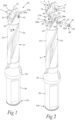
- the cutting head 1 is designed for detachable attachment to an elongated tool body 21 at a front end thereof and is configured to form a drilling tool 20 in the form of a twist drill together with the tool body 21 when attached to it, as illustrated in Figs 1-6 .
- the drilling tool 20 is intended to be rotated for machining of a workpiece by drilling.
- Figs 1 and 3-6 the drilling tool 20 is shown with the cutting head 1 mounted to the tool body 21 and with the drilling tool 20 ready for machining of a workpiece.
- the drilling tool 20 is configured to be rotated about an axis of rotation 22.
- the intended direction of rotation of the drilling tool 20 for machining is marked with the arrow R in Figs 1 , 3 and 5 .
- the direction of rotation R constitutes the direction in which the drilling tool 20 is intended to be rotated about the axis of rotation 22 in order to drill a hole in a workpiece.
- the cutting head 1 is made of hard and wear-resistant material, preferably cemented carbide, and the tool body 21 is preferably made of steel or other suitable metallic material.
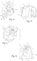
- the cutting head 1 included in the drilling tool 20 of Figs 1-6 is illustrated in closer detail in Figs 7a-7l .
- the cutting head 1 has a rear end 1b configured to face the tool body 21 and an opposite front end 1a.
- a longitudinal centre axis C1 of the cutting head 1 extends between the rear end 1b and the front end 1a of the cutting head, wherein this centre axis C1 is configured to coincide with the axis of rotation 22 of the drilling tool 20 when the cutting head is attached to the tool body 21.
- the cutting head 1 comprises a front face 2 located at the front end 1a of the cutting head and at least one external chip flute 3 that extends in a helically curved path along the cutting head 1 from the front face 2 towards the rear end 1b of the cutting head.
- the cutting head 1 is provided with two such chip flutes 3, which extend diametrically opposite each other and alongside of each other.
- the cutting head 1 has 180° rotational symmetry about the centre axis C1 of the cutting head.
- a major cutting edge 4 is formed at an intersection between each chip flute 3 and the front face 2 of the cutting head. At its radially innermost end, each major cutting edge 4 adjoins to a minor cutting edge 5 that extends on the front face 2 of the cutting head from the associated chip flute 3 towards a tip TP provided at the centre of the front face 2.
- the tip TP constitutes the axially foremost part of the cutting head 1 and may be provided with a so-called chisel edge.
- a clearance surface 7 is arranged on the front face 2 of the cutting head 1 behind each cutting edge 4, 5, as seen in the intended direction of rotation R of the drilling tool 20.
- a margin 10 provided on a peripheral surface 6 of the cutting head 1 extends adjacent to each chip flute 3 along at least a part thereof from the front face 2 towards the rear end 1b of the cutting head.
- Each margin 10 has an upper end 10a facing the front end 1a of the cutting head and an opposite lower end 10b.
- Each margin 10 comprises a radially outwardly facing margin land 11, which extends between the upper and lower ends 10a, 10b of the margin and which has a leading longitudinal edge 12 and an opposite trailing longitudinal edge 13.
- the leading and trailing longitudinal edges 12, 13 extend between the upper and lower ends 10a, 10b of the margin on opposite sides of the margin land 11.
- the margin land 11 of each margin 10 is convexly curved as seen in any plane that is perpendicular to the centre axis C1 of the cutting head 1 and extends across the margin land 11.
- the leading longitudinal edge 12 of the margin land 11 of each margin 10 has an upper end point P1, which constitutes the axially foremost point of the leading longitudinal edge 12 and through which the leading longitudinal edge 12 is connected to the adjacent major cutting edge 4, and an opposite lower end point P2, which constitutes the axially rearmost point of the leading longitudinal edge 12.
- the leading longitudinal edge 12 has:
- the distance d1 between the centre axis C1 of the cutting head 1 and said upper edge section 12a is the same, or at least essentially the same, all along the upper edge section 12a, whereas the distance d2 between the centre axis C1 of the cutting head 1 and said lower edge section 12b is gradually reduced along the lower edge section 12b as seen in a direction along the lower edge section 12b from said dividing point P3 to the lower end point P2 of the leading longitudinal edge.
- the part of the margin 10 located between the lower end 10b of the margin and a plane PL1 (see Fig 7c ) that is perpendicular to the centre axis C1 of the cutting head 1 and contains said dividing point P3 has a back tapered shape, whereas the upper part of the margin 10 located between the upper end 10a of the margin and said plane PL1 is non-back tapered.
- Said gradual decrease of the distance d2 between the centre axis C1 of the cutting head 1 and the lower edge section 12b of each leading longitudinal edge 12 is preferably continuous all along the lower edge section 12 as seen in the direction along the lower edge section 12b from the dividing point P3 to the lower end point P2 of the leading longitudinal edge.
- the lower edge sections 12b of the leading longitudinal edges 12 of both margins 10 are contained in the conical surface of one and the same imaginary right circular cone with a centre axis coinciding with the centre axis C1 of the cutting head 1.
- the upper edge sections 12a of the leading longitudinal edges 12 of both margins 10 are contained in the curved surface of one and the same imaginary right circular cylinder with a centre axis coinciding with the centre axis C1 of the cutting head 1 and a radius corresponding to the distance d1 between the centre axis C1 of the cutting head 1 and each upper edge section 12a.
- the upper edge section 12a of the leading longitudinal edge 12 of the margin land 11 of each margin 10 suitably has a length h1 in the axial direction of the cutting head 1 that corresponds to 3-20%, preferably 5-10%, of the total length h of the leading longitudinal edge 12 in the axial direction of the cutting head.
- the trailing longitudinal edge 13 of the margin land 11 is preferably located closer to the centre axis C1 of the cutting head 1 than the leading longitudinal edge 12 of the margin land 11 as seen in any plane that is perpendicular to the centre axis C1 of the cutting head and extends across the margin land 11.
- the distance d3 between the centre axis C1 of the cutting head 1 and the trailing longitudinal edge 13 of the margin land 11 is slightly smaller than the distance d1, d2 between the centre axis C1 of the cutting head 1 and the leading longitudinal edge 12 of the margin land 11 as seen in any plane that is perpendicular to the centre axis C1 of the cutting head and extends across the margin land 11.
- the distance between the centre axis C1 of the cutting head 1 and the margin land 11 is preferably continuously reduced from the leading longitudinal edge 12 to the trailing longitudinal edge 13 of the margin land 11 in any plane that is perpendicular to the centre axis C1 of the cutting head 1 and extends across the margin land 11.
- the axial support surface 36 on the tool body 21 is perpendicular to the centre axis C2 of the tool body 21, wherein the axial abutment surface 16 on the cutting head 1 is perpendicular to the centre axis C1 of the cutting head 1.
- the cutting head 1 of the present invention may as an alternative be fixed to the coupling legs of a tool body in any other suitable manner.
- the coupling portion of the cutting head 1 may for instance be configured to be fixed to the coupling legs of the tool body by press fit, for instance in the manner described in US 8 430 609 B2 , wherein the coupling portion of the cutting head is rotatable in the space between the coupling legs between a disengagement position, in which external clamping surfaces on the coupling portion of the cutting head are disengaged from corresponding internal clamping surfaces on the coupling legs and the torque surfaces on the cutting head are separated from the corresponding torque transfer surfaces on the coupling legs, and an engagement position, in which the external clamping surfaces on the coupling portion of the cutting head are in press fit engagement with the internal clamping surfaces on the coupling legs and the torque surfaces on the cutting head abut against the corresponding torque transfer surfaces on the coupling legs.
- the cutting head may be attached to and released from the tool body in a simple and quick manner by being rotated in relation to the
Landscapes
- Engineering & Computer Science (AREA)
- Mechanical Engineering (AREA)
- Drilling Tools (AREA)
Priority Applications (2)
| Application Number | Priority Date | Filing Date | Title |
|---|---|---|---|
| EP23219040.5A EP4574320A1 (de) | 2023-12-21 | 2023-12-21 | Schneidkopf für ein bohrwerkzeug und bohrwerkzeug mit einem solchen schneidkopf |
| PCT/EP2024/084778 WO2025131735A1 (en) | 2023-12-21 | 2024-12-05 | Cutting head for a drilling tool and drilling tool comprising such a cutting head |
Applications Claiming Priority (1)
| Application Number | Priority Date | Filing Date | Title |
|---|---|---|---|
| EP23219040.5A EP4574320A1 (de) | 2023-12-21 | 2023-12-21 | Schneidkopf für ein bohrwerkzeug und bohrwerkzeug mit einem solchen schneidkopf |
Publications (1)
| Publication Number | Publication Date |
|---|---|
| EP4574320A1 true EP4574320A1 (de) | 2025-06-25 |
Family
ID=89308016
Family Applications (1)
| Application Number | Title | Priority Date | Filing Date |
|---|---|---|---|
| EP23219040.5A Withdrawn EP4574320A1 (de) | 2023-12-21 | 2023-12-21 | Schneidkopf für ein bohrwerkzeug und bohrwerkzeug mit einem solchen schneidkopf |
Country Status (2)
| Country | Link |
|---|---|
| EP (1) | EP4574320A1 (de) |
| WO (1) | WO2025131735A1 (de) |
Citations (6)
| Publication number | Priority date | Publication date | Assignee | Title |
|---|---|---|---|---|
| US4080093A (en) * | 1974-11-18 | 1978-03-21 | Hartmetallwerkzeugfabrik Andreas Maier Kg | Drill for electronic conductor plates |
| US4561813A (en) * | 1983-06-06 | 1985-12-31 | M. A. Ford Mfg. Co., Inc. | Drill |
| US8430609B2 (en) | 2008-04-14 | 2013-04-30 | Seco Tools Ab | Tool, tool body and cutting head |
| WO2015140781A1 (en) * | 2014-03-19 | 2015-09-24 | Iscar Ltd. | Drill or drill head with burnishing margin |
| US11311948B2 (en) | 2017-07-10 | 2022-04-26 | Sandvik Intellectual Property Ab | Rotary drill tool with insert centring surfaces |
| US20230256524A1 (en) * | 2020-07-27 | 2023-08-17 | Mitsubishi Materials Corporation | Drill |
-
2023
- 2023-12-21 EP EP23219040.5A patent/EP4574320A1/de not_active Withdrawn
-
2024
- 2024-12-05 WO PCT/EP2024/084778 patent/WO2025131735A1/en active Pending
Patent Citations (6)
| Publication number | Priority date | Publication date | Assignee | Title |
|---|---|---|---|---|
| US4080093A (en) * | 1974-11-18 | 1978-03-21 | Hartmetallwerkzeugfabrik Andreas Maier Kg | Drill for electronic conductor plates |
| US4561813A (en) * | 1983-06-06 | 1985-12-31 | M. A. Ford Mfg. Co., Inc. | Drill |
| US8430609B2 (en) | 2008-04-14 | 2013-04-30 | Seco Tools Ab | Tool, tool body and cutting head |
| WO2015140781A1 (en) * | 2014-03-19 | 2015-09-24 | Iscar Ltd. | Drill or drill head with burnishing margin |
| US11311948B2 (en) | 2017-07-10 | 2022-04-26 | Sandvik Intellectual Property Ab | Rotary drill tool with insert centring surfaces |
| US20230256524A1 (en) * | 2020-07-27 | 2023-08-17 | Mitsubishi Materials Corporation | Drill |
Also Published As
| Publication number | Publication date |
|---|---|
| WO2025131735A1 (en) | 2025-06-26 |
Similar Documents
| Publication | Publication Date | Title |
|---|---|---|
| US5863162A (en) | Tool body and removable tool tip for chip removing machining | |
| US5340246A (en) | Indexable insert drill and an insert with a symmetrical drill point and cutting edges of different lengths | |
| CA2546058C (en) | Cutting insert with helical geometry and holder therefor | |
| EP2123381B1 (de) | Bohrkörper | |
| US7004691B2 (en) | Deep hole cutter | |
| EP2368657B1 (de) | Drehbares Werkzeug zur spanenden Bearbeitung sowie Schneideinsatz und Grundkörper dafür | |
| US5964555A (en) | Milling tool and cutter head therefor | |
| JP6993344B2 (ja) | 一体的に形成されたねじ付シャンクコネクタを備えた交換可能な正面フライスヘッド | |
| EP2272611A1 (de) | Tieflochbohrwegwerfspitze und tieflochbohrerkopf | |
| EP2150371B1 (de) | Bohrkörper für spanentfernende bearbeitung | |
| US6821061B2 (en) | Three-edged drill for chip forming machining | |
| US9901994B2 (en) | Rotating tool and tool head | |
| EP1679143B1 (de) | Bohrwerkzeug | |
| EP4574320A1 (de) | Schneidkopf für ein bohrwerkzeug und bohrwerkzeug mit einem solchen schneidkopf | |
| EP4574319A1 (de) | Schneidkopf für ein bohrwerkzeug und bohrwerkzeug mit einem solchen schneidkopf | |
| JP4661229B2 (ja) | ガンドリル用インサート及びインサート式ガンドリル | |
| WO2025114321A1 (en) | Rotary cutting tool with replaceable cutting head | |
| US11951553B2 (en) | Rotatable cutting head having tip portion with three radially extending cutting edges forming a rectilinear rotational profile | |
| US20230381870A1 (en) | Drill point | |
| JP2024087522A (ja) | ドリルヘッド及び刃先交換式ドリル | |
| EP4494792A1 (de) | Schaftfräser | |
| WO2025105294A1 (ja) | ドリル | |
| WO2025105312A1 (ja) | ドリル | |
| JP2003291016A (ja) | スローアウェイ式ドリル | |
| HK1156569B (en) | Core drill |
Legal Events
| Date | Code | Title | Description |
|---|---|---|---|
| PUAI | Public reference made under article 153(3) epc to a published international application that has entered the european phase |
Free format text: ORIGINAL CODE: 0009012 |
|
| STAA | Information on the status of an ep patent application or granted ep patent |
Free format text: STATUS: THE APPLICATION HAS BEEN PUBLISHED |
|
| AK | Designated contracting states |
Kind code of ref document: A1 Designated state(s): AL AT BE BG CH CY CZ DE DK EE ES FI FR GB GR HR HU IE IS IT LI LT LU LV MC ME MK MT NL NO PL PT RO RS SE SI SK SM TR |
|
| STAA | Information on the status of an ep patent application or granted ep patent |
Free format text: STATUS: THE APPLICATION HAS BEEN WITHDRAWN |
|
| 18W | Application withdrawn |
Effective date: 20251217 |