EP4574375A1 - Werkzeug mit variabler steifigkeit - Google Patents
Werkzeug mit variabler steifigkeit Download PDFInfo
- Publication number
- EP4574375A1 EP4574375A1 EP24214089.5A EP24214089A EP4574375A1 EP 4574375 A1 EP4574375 A1 EP 4574375A1 EP 24214089 A EP24214089 A EP 24214089A EP 4574375 A1 EP4574375 A1 EP 4574375A1
- Authority
- EP
- European Patent Office
- Prior art keywords
- moulding tool
- composite
- composite article
- moulding
- tool
- Prior art date
- Legal status (The legal status is an assumption and is not a legal conclusion. Google has not performed a legal analysis and makes no representation as to the accuracy of the status listed.)
- Pending
Links
Images




Classifications
-
- B—PERFORMING OPERATIONS; TRANSPORTING
- B29—WORKING OF PLASTICS; WORKING OF SUBSTANCES IN A PLASTIC STATE IN GENERAL
- B29B—PREPARATION OR PRETREATMENT OF THE MATERIAL TO BE SHAPED; MAKING GRANULES OR PREFORMS; RECOVERY OF PLASTICS OR OTHER CONSTITUENTS OF WASTE MATERIAL CONTAINING PLASTICS
- B29B11/00—Making preforms
- B29B11/14—Making preforms characterised by structure or composition
- B29B11/16—Making preforms characterised by structure or composition comprising fillers or reinforcement
-
- B—PERFORMING OPERATIONS; TRANSPORTING
- B29—WORKING OF PLASTICS; WORKING OF SUBSTANCES IN A PLASTIC STATE IN GENERAL
- B29C—SHAPING OR JOINING OF PLASTICS; SHAPING OF MATERIAL IN A PLASTIC STATE, NOT OTHERWISE PROVIDED FOR; AFTER-TREATMENT OF THE SHAPED PRODUCTS, e.g. REPAIRING
- B29C33/00—Moulds or cores; Details thereof or accessories therefor
- B29C33/38—Moulds or cores; Details thereof or accessories therefor characterised by the material or the manufacturing process
-
- B—PERFORMING OPERATIONS; TRANSPORTING
- B29—WORKING OF PLASTICS; WORKING OF SUBSTANCES IN A PLASTIC STATE IN GENERAL
- B29C—SHAPING OR JOINING OF PLASTICS; SHAPING OF MATERIAL IN A PLASTIC STATE, NOT OTHERWISE PROVIDED FOR; AFTER-TREATMENT OF THE SHAPED PRODUCTS, e.g. REPAIRING
- B29C70/00—Shaping composites, i.e. plastics material comprising reinforcements, fillers or preformed parts, e.g. inserts
- B29C70/04—Shaping composites, i.e. plastics material comprising reinforcements, fillers or preformed parts, e.g. inserts comprising reinforcements only, e.g. self-reinforcing plastics
- B29C70/28—Shaping operations therefor
- B29C70/30—Shaping by lay-up, i.e. applying fibres, tape or broadsheet on a mould, former or core; Shaping by spray-up, i.e. spraying of fibres on a mould, former or core
- B29C70/34—Shaping by lay-up, i.e. applying fibres, tape or broadsheet on a mould, former or core; Shaping by spray-up, i.e. spraying of fibres on a mould, former or core and shaping or impregnating by compression, i.e. combined with compressing after the lay-up operation
- B29C70/345—Shaping by lay-up, i.e. applying fibres, tape or broadsheet on a mould, former or core; Shaping by spray-up, i.e. spraying of fibres on a mould, former or core and shaping or impregnating by compression, i.e. combined with compressing after the lay-up operation using matched moulds
-
- B—PERFORMING OPERATIONS; TRANSPORTING
- B29—WORKING OF PLASTICS; WORKING OF SUBSTANCES IN A PLASTIC STATE IN GENERAL
- B29K—INDEXING SCHEME ASSOCIATED WITH SUBCLASSES B29B, B29C OR B29D, RELATING TO MOULDING MATERIALS OR TO MATERIALS FOR MOULDS, REINFORCEMENTS, FILLERS OR PREFORMED PARTS, e.g. INSERTS
- B29K2883/00—Use of polymers having silicon, with or without sulfur, nitrogen, oxygen, or carbon only, in the main chain, as mould material
-
- B—PERFORMING OPERATIONS; TRANSPORTING
- B29—WORKING OF PLASTICS; WORKING OF SUBSTANCES IN A PLASTIC STATE IN GENERAL
- B29K—INDEXING SCHEME ASSOCIATED WITH SUBCLASSES B29B, B29C OR B29D, RELATING TO MOULDING MATERIALS OR TO MATERIALS FOR MOULDS, REINFORCEMENTS, FILLERS OR PREFORMED PARTS, e.g. INSERTS
- B29K2905/00—Use of metals, their alloys or their compounds, as mould material
- B29K2905/08—Transition metals
- B29K2905/12—Iron
-
- B—PERFORMING OPERATIONS; TRANSPORTING
- B29—WORKING OF PLASTICS; WORKING OF SUBSTANCES IN A PLASTIC STATE IN GENERAL
- B29K—INDEXING SCHEME ASSOCIATED WITH SUBCLASSES B29B, B29C OR B29D, RELATING TO MOULDING MATERIALS OR TO MATERIALS FOR MOULDS, REINFORCEMENTS, FILLERS OR PREFORMED PARTS, e.g. INSERTS
- B29K2995/00—Properties of moulding materials, reinforcements, fillers, preformed parts or moulds
- B29K2995/0037—Other properties
- B29K2995/0082—Flexural strength; Flexion stiffness
-
- B—PERFORMING OPERATIONS; TRANSPORTING
- B29—WORKING OF PLASTICS; WORKING OF SUBSTANCES IN A PLASTIC STATE IN GENERAL
- B29L—INDEXING SCHEME ASSOCIATED WITH SUBCLASS B29C, RELATING TO PARTICULAR ARTICLES
- B29L2031/00—Other particular articles
- B29L2031/08—Blades for rotors, stators, fans, turbines or the like, e.g. screw propellers
- B29L2031/082—Blades, e.g. for helicopters
Definitions
- the present disclosure concerns a variable stiffness tool. Specifically, it concerns a variable stiffness moulding tool for moulding composite article preforms.
- Moulding tools may be used during the manufacturing process of composite fan blades, with these moulding tools being either hard tools (stiff) or soft tools (flexible).
- a moulding tool for moulding a composite article preform.
- the composite article preform has a thickness that varies between different regions of the composite article preform.
- the moulding tool comprises a first portion for moulding a corresponding first region of the composite article preform, the first portion of the moulding tool comprising a first material.
- the moulding tool also comprises a second portion for moulding a corresponding second region of the composite article preform, the second portion of the moulding tool comprising a second material.
- the moulding tool also comprises a transition portion between the first portion and the second portion.
- the transition portion comprises the first material and the second material.
- the first material and the second material are different.
- the first portion and the second portion have different stiffnesses.
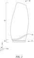
- FIG. 2 provides an illustration of a composite article in the form of a fan blade 30 for a gas turbine engine.
- the fan blade 30 must satisfy both aerodynamic and structural requirements, in that the fan blade 30 must have a high aerodynamic efficiency whilst also being mechanically robust, for example, by being able to tolerate impact events such as a bird striking the fan blade during take-off.
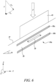
- each of the first moulding tool 40' and second moulding tool 40" has a surface profile that substantially matches (corresponds to) the desired surface profile of one of the surfaces of the blade, i.e., one of the first moulding tool 40' and the second moulding tool 40" substantially matches the desired surface profile of the pressure surface of the fan blade 30, while the other moulding tool substantially matches the desired surface profile of the suction surface of the fan blade 30.
- Both the profiles of the moulding tools also comprise a representation of a surface of a root region of the fan blade.
- the first moulding tool 40' and second moulding tool 40" may therefore each mould a surface of the aerodynamic region and the root region of the composite article preform 35.
- the first moulding tool 40' is above the composite layers of the composite article preform 35.
- the first moulding tool 40 may therefore also be referred to as a top moulding tool 40'.
- the second moulding tool 40 as it is below the composite layers 35, may be referred to as a bottom moulding tool 40".
- the uncured composite article preform 35 may be placed in a vacuum bag and placed in an autoclave for curing.
- the evacuation of air from the vacuum bag presses the first moulding tool 40' and, optionally, the second moulding tool 40" against the layers of composite material of the uncured composite article preform 35.
- Vacuum debulking also has an additional advantage, in that as the first moulding tool 40' and the second moulding tool 40" is significantly stiffer than the uncured composite material, the outer profile of the composite material will adapt to the profile of the first moulding tool 40' and optionally, the second moulding tool 40".
- the moulding tool 40 (for example, first moulding tool 40' and the second moulding tool 40") to be made from a stiff material, as a stiff moulding tool reduces the degree of surface undulation in the resulting cured preform. If made from a stiff material, the tool may be referred to as a "hard tool” or "hard tooling".
- the moulding tool 40 may comprise cured composite material, such as cured carbon composite material.
- cured composite material such as cured carbon composite material.
- composite materials have the advantage that they produce a tool which is typically lighter-weight than a corresponding metallic tool.
- the thermal expansion of the moulding tool may match or substantially match the composite material to be cured. This may be desirable because it may reduce distortion and/or thermal stresses of the composite article preform.
- the material forming the moulding tool 40 has a low coefficient of thermal expansion. In this way, a good control of the outer profile of the composite material may be achieved, with minimal distortion of the outer profile occurring due to the temperature change experienced during curing.
- the moulding tool 40 may comprise a material that is an iron-nickel alloy, e.g. FeNi36 or INVAR ® iron-nickel alloy, which has a low coefficient of thermal expansion (and is commercially available from Magellan Metals).
- an iron-nickel alloy e.g. FeNi36 or INVAR ® iron-nickel alloy, which has a low coefficient of thermal expansion (and is commercially available from Magellan Metals).
- the internal orientation of the resulting layers of composite material of the cured carbon composite preform can be non-optimal.
- the internal orientation of the layers of composite material in cured composite article preform 35 may be locally different to that the composite layer structure of the uncured composite article preform 35, prior to placing the uncured preform in a vacuum bag for vacuum debulking.
- FIG. 5 shows an example of a sectioned cured layer structure, representing a transition region between a first region of the composite article preform 35 that will, in a finished fan blade, form an aerodynamic region of the fan blade, and a second region of the composite article preform 35 that will, in a finished fan blade, form a root region of the fan blade.
- FIG. 5 is merely one example of internal undulations 35a that may form within the composite article preform 35.
- undulations may form in other parts of the transition region to that shown in FIG. 5 .
- the interior layer structure of the composite article can have local internal undulations 35a.
- These internal undulations 35a may be undesirable because they reduce the ability of the composite article preform, and hence the composite article, to support a load, as the fibers in the undulating composite layers are not always substantially aligned with the direction of application of that load. The resulting cured composite article may therefore fail prematurely.
- the aerodynamic region of a composite fan blade has a through-thickness that is significantly smaller than the root region of the blade.
- a cross-section through the root region of the blade may contain a substantially greater number of layers of composite material than the aerodynamic region.
- FIG. 6 shows that as a consequence of this increase in thickness between the aerodynamic region and the root region of the fan blade, the composite layers in the transition region between the aerodynamic region and the root region, in which undesirable sub-surface (internal) undulations 35a may form in the composite layer structure, may be inclined at an angle ⁇ to the direction in which moulding tool 40 (as first moulding tool 40' and/or second moulding tool 40") is applied. It will be appreciated that if the moulding tool 40 is to produce a conforming aerodynamic surface in the aerodynamic region of the preform, compression of the layers within the aerodynamic region of the preform is required.
- the moulding tool 40 is made from a stiff material, as a substantially uniform amount of compression (displacement) occurs in the aerodynamic region and root region of the preform, substantially more compression occurs between layers in the aerodynamic region than in the root region, as there are fewer layers in the aerodynamic region than the root region.
- the layer structure within the aerodynamic region of the blade may be denser (more compact) than in the root region. Indeed, full-fibre impregnation of the matrix material 38 between fibres in the root region may not have occurred in the root region, whilst voids, caused by the presence of air bubbles may also remain.
- the root region of the composite fan blade preform 35 may conform to a required exterior profile, as the layers within the root region may not be sufficiently dense, due to insufficient compaction, the root region of the composite fan blade may be weaker than design intent. As this region of the fan blade must withstand high loads, this region of the fan blade is highly stressed. A weaker composite structure in this area may therefore lead to premature failure of the fan blade 30.
- a potential way to overcome this problem is to arrange the layer structure of the root region such that more through-thickness compression (e.g., displacement in "-Z" direction takes place in the root region of the fan blade 30 than in the aerodynamic region of the fan blade 30.
- composite article preform 35 composite fan blade preform 35
- this may produce a composite article preform 35 (composite fan blade preform 35) that has both an acceptable degree of compaction and an acceptable outer profile, under other circumstances this may lead to an undesirable, undulating arrangement of layers within the composite article preform, as illustrated in FIG. 5 .
- FIG. 6 illustrates the forces acting on uncured layers of the composite material due to the application of a force, F generated by vacuum debulking, acting on a moulding tool 40.
- a force, F generated by vacuum debulking acting on a moulding tool 40.
- FIG. 6 shows that a surface of the moulding tool 40 is in direct contact with an outer surface 37 of the uncured layers, it will be appreciated that in some circumstances a release film (not shown) may be placed between the moulding tool 40 and the outer surface 37.
- FIG. 6 also illustrates that these layers 36 may not be aligned with a principal axis of the component (i.e. the layers do not lie substantially in the "X-Y" plane) but may instead be inclined at an angle ⁇ to the "X-Y" plane. This may occur in regions of the uncured composite article preform in which there is a rate of change of through-thickness, such as in transition region between the thin aerodynamic region and thick root region of the composite article preform.
- force F may be resolved into the sum of a first force F N that is normal (i.e., perpendicular) to the plane of a composite layer and a force F P that is in the plane of the composite layer.
- Force F P is a shearing force that acts to promote shearing (slippage) 39 between adjacent layers 36a, 36b of uncured fiber. Despite the presence of shear force F P , slippage 39 will not occur if an in plane resistive force is greater than the shear force.
- the resistive force may be proportional to the normal contact force F N , with the ratio of F N to F P in turn dependent upon angle ⁇ .
- the resistive force may also be dependent upon the degree of overlap between adjacent ply layers, as this affects the area over which shearing must occur during slippage.
- the resistive force may also be dependent upon the degree of in-plane curvature of the adjacent ply layers, for a given contact area.
- the likelihood of slippage 39 between layers occurring may be dependent upon a desired rate of change of thickness of the composite article, as a higher rate of change of thickness increases the value of angle ⁇ , increasing the ratio of F P to F N .
- soft tooling may have the disadvantage that although it is more effective at reducing undulations between composite layers within the composite article preform 35, it is less effective than hard tooling in reducing surface undulations in the uncured preform, as it deforms, potentially reducing the aerodynamic efficiency of the resulting composite fan blade.
- the inventors have determined that it is beneficial to produce a moulding tool 40 for moulding a composite article preform 35 that has a variable stiffness, such that the moulding tool 40 has a higher stiffness for moulding regions of the composite article preform 35 where close control of surface profile is required, and a lower stiffness for moulding regions of the composite article preform, where the localised geometry of the uncured preform is such that slippage may occur between uncured layers of composite material, creating internal undulations with the composite article preform 35.
- FIG. 8 provides an example of a moulding tool 40 for moulding a composite article preform 35.
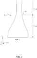
- the composite article preform 35 may be as illustrated in FIG. 3 - i.e. the composite article preform does not have a non-constant thickness, but instead has a thickness that varies between different regions of the preform.
- one region of the preform may be 2 to 5 times thicker than another part of the preform. In a further example, it may be 2.5 to 4.5 times thicker. In a specific embodiment, the preform is 3 times thicker.
- the moulding tool 40 comprises several portions.
- the different portions of the moulding tool 40 are configured to provide a compressive force against corresponding different regions of the composite article preform 35.
- the different portions of the moulding tool 40 are configured to have different stiffnesses to each other.
- a first portion 41 of the moulding tool 40 may be configured to have a stiffness akin to that of a hard tool
- a second portion 42 of the moulding tool may be configured to have a stiffness akin to that of a soft tool.
- the first portion 41 comprises a first material 50.
- the second portion 42 comprises a second material 51.
- the first portion 41 may not comprise the second material 50 while the second portion 42 may not comprise the first material 51.
- the first material 50 is different to the second material 51.
- the first material 50 has a different stiffness to the second material 51; i.e., the Young's Modulus of the first material 50 is different to the Young's Modulus of the second material 51.
- the moulding tool 40 of FIG. 8 may therefore be described as a multi-material variable stiffness tool.
- the first material 50 is stiffer than the second material 51.
- the first material 50 may be a metal, a metal alloy e.g. INVAR (RTM) iron-nickel alloy, or a composite e.g. a carbon composite.
- the second material 51 may be an elastomer such as a silicone rubber.
- the moulding tool 40 additionally comprises a transition portion 43, separating the first portion 41 and second portion 42, and having a variable stiffness such that its stiffness is substantially equal is the stiffness of the first portion at an interface with the first portion, and a lower stiffness that is substantially equal to the stiffness of the second portion at an interface with the second portion.
- the transition portion 43 comprises both the first material 50 and the second material 51.
- the transition portion may comprise a layered structure in which one of the first material 50 and the second material 51 overlays the other of the first material 50 and the second material 51.
- the layer of first material 50 of the transition portion 43 and/or layer of second material 51 of the transition portion 43 may not have a constant thickness but may reduce in thickness along the length of the transition portion.
- at least one layer may be tapered, such that a thickness of the layer reduces along the tool.
- the thickness of the layer may reduce to substantially zero. Tapering reduces the likelihood of forming an imprint of the tool on a surface of the composite article preform to be moulded. Reducing the likelihood of forming an imprint of the tool on the surface of the composite article preform is desirable, as it reduces the likelihood (probability) of causing a stress concentration on the surface, which could act as a failure initiator in a finished composite article.
- a thickness of the first material 50 in the layered structure of the transition portion 43 may decrease with distance from the first portion 41 of the moulding tool 40 such that the layer of first material 50 has a minimum thickness at an interface between the transition portion 43 and the second portion 42.
- the minimum thickness of this layer may be substantially zero at this interface.
- the change in thickness of the first material may be continuous, in that there are no discrete changes in thickness of the first material.
- a thickness of the second material 51 in the layered structure of the transition portion 43 may decreases with distance from the second portion 42 of the moulding tool such that the layer of second material 51 has a minimum thickness at an interface between the transition portion 43 and the first portion 42.
- the minimum thickness of this layer may be substantially zero at this interface.
- the change in thickness of the second material may be continuous, in that there are no step changes in thickness of the second material.
- the layer of the first material 50 of the transition portion 43 may taper towards a line contact at an interface between the transition portion 53 and the second portion 42.
- the layer of the second material 51 of the transition portion 43 may taper towards a line contact at an interface between the transition portion 43 and the first portion 41.
- the tapering of the first and/or second material within the transition portion 43 may be desirable because this ensures a continuous change in stiffness of the tool along the span of the preform. This avoids the creation of a defined indentation in the surface of the preform at the interface between the first and second materials on the surface of the tool that faces the preform.
- the first material and /or second material may therefore have a shallow taper angle.
- the first material may have a shallow taper angle, such as 20 degrees or less. The shallow taper angle increases the flexibility of the first material, and hence the moulding tool, over a greater sub-portion of the transition portion.
- transition portion 43 may have a variable stiffness such that its stiffness is substantially equal is the stiffness of the first portion at the interface with the first portion, and a different stiffness that is substantially equal to the stiffness of the second portion at the interface with the second portion.
- the location and/or spatial extent of the transition portion 43 of the moulding tool 40 may be determined based upon a desired rate of change of thickness of the composite article preform.
- the location and/or spatial extent of the transition portion 43 represents a balance between maximising the spatial extent of the first portion 41, whilst mitigating the probability of the increased stiffness of the first material causing undulations in the layers of composite material of preform 35 during vacuum debulking.
- the location and/or a spatial extent of the transition portion of the moulding tool may be based upon a desired rate of change of thickness of the composite article preform, such that the local stiffness of the tool is reduced in regions of the tool which overlay higher desired rates of change in thickness of the composite article preform.
- the transition portion 43 may therefore be proximal to, but not necessarily overlaying regions of the preform in which there is higher desired rate of change in thickness of the composite article preform.
- first portion 41 and transition portion 43 of the moulding tool 40 may substantially overlay what will become the aerodynamic region 31 of the fan blade 30, whereas the second portion 42 of the moulding tool 40 may substantially overlay what will become the root region 32 of the fan blade 30.
- a lateral force (for example, in the X-Y plane of FIG 7 ) may be generated, acting on the moulding tool 40.
- this may cause the moulding tool to move laterally (e.g. in the X-Y plane) relative to the uncured composite article preform, in addition to the desired direction of compression. Lateral movement of the moulding tool in this way may be undesirable as it may be a cause of internal undulations as adjacent layers of uncured composite material may slide relative to each other.
- the moulding tool 40 may therefore additionally comprise at least one guide.
- the at least one guide is configured to enable the moulding tool to move in a desired direction (for example, the -Z direction of FIG 7 ), whilst preventing the moulding tool moving in an undesired direction (for example, in the X-Y plane of FIG 7 ). Relative movement between the moulding tool and the composite article preform may therefore be controlled when the moulding tool is compressed against the composite article preform.
- the at least one guide may be any suitable guide.
- the at least one guide may be a through hole in the moulding tool, aligned in the direction of desired movement, relative to which a fixed guide pin passing through the guide may slide.
- the first material 50 and second material 51 may be joined in the transition portion 43 by any suitable way.
- the first material 50 and second material 51 may be joined by an adhesive.
- the first material 50 and the second material 51 may be joined by at least one mechanical fastener.
- the at least one mechanical fastener may comprise at least one corresponding insert that is embedded within the second material 51 and is configured to connect with a corresponding fixing connected to or connectable with the first material 50.
- the insert embedded within the second material 51 may be flush with a surface of the second potion
- At least one of a first moulding tool 40' and second moulding tool 40" may comprise a first portion 41', 41", second portion 42', 42" and transition portion 43', 43".
- first moulding tool 40' comprises both the first material 50 and 51
- bottom tool 40" is a conventional moulding tool, comprising only either the first material 50 or the second material 51.
- first moulding tool 40' as a top tool 40', may only comprise the first material 50
- second moulding tool 40" as a bottom tool, 40" may be a variable stiffness tool as disclosed above, comprising both the first and second materials 50, 51.
- both the first moulding tool 40' and the second moulding tool 40" may comprise both the first and second materials 50, 51.
- a moulding tool 40 may be a conventional moulding tool or may be a multi-material variable stiffness tool may be made based upon the desired rate change of thickness of the composite article preform and/or the desired degree of curvature of the outer profile of the uncured preform that faces the moulding tool.
- FIG 10 illustrates a method 100 of forming a composite article preform using the above moulding tool.
- the method comprises the steps of: -
- steps 101 - 104 are shown sequentially, some steps may be performed simultaneously. For example, steps 103 and 104 may be performed simultaneously.
- the above method may be performed as part of a wider manufacturing process. For example, once the step 104 has concluded, at least one machining operation may be performed on the composite article preform and/or at least one protective coating may be applied to the composite article preform to form a composite article, such as a gas turbine engine composite fan blade.
Landscapes
- Engineering & Computer Science (AREA)
- Mechanical Engineering (AREA)
- Manufacturing & Machinery (AREA)
- Chemical & Material Sciences (AREA)
- Composite Materials (AREA)
- Moulding By Coating Moulds (AREA)
Applications Claiming Priority (1)
| Application Number | Priority Date | Filing Date | Title |
|---|---|---|---|
| GBGB2319599.3A GB202319599D0 (en) | 2023-12-20 | 2023-12-20 | Variable stiffness tool |
Publications (1)
| Publication Number | Publication Date |
|---|---|
| EP4574375A1 true EP4574375A1 (de) | 2025-06-25 |
Family
ID=89662978
Family Applications (1)
| Application Number | Title | Priority Date | Filing Date |
|---|---|---|---|
| EP24214089.5A Pending EP4574375A1 (de) | 2023-12-20 | 2024-11-20 | Werkzeug mit variabler steifigkeit |
Country Status (3)
| Country | Link |
|---|---|
| US (1) | US20250205936A1 (de) |
| EP (1) | EP4574375A1 (de) |
| GB (1) | GB202319599D0 (de) |
Citations (4)
| Publication number | Priority date | Publication date | Assignee | Title |
|---|---|---|---|---|
| US5520532A (en) * | 1994-08-01 | 1996-05-28 | United Technologies Corporation | Molding assembly for forming airfoil structures |
| US6290895B1 (en) * | 1997-10-14 | 2001-09-18 | General Electric Company | Selectively flexible caul and method of use |
| US20110024032A1 (en) * | 2008-01-18 | 2011-02-03 | Scott Barber | Semi-rigid tool |
| US20200108567A1 (en) * | 2018-10-08 | 2020-04-09 | Bell Helicopter Textron Inc. | Caul body and a method for forming a composite structure |
-
2023
- 2023-12-20 GB GBGB2319599.3A patent/GB202319599D0/en not_active Ceased
-
2024
- 2024-11-20 EP EP24214089.5A patent/EP4574375A1/de active Pending
- 2024-11-26 US US18/960,510 patent/US20250205936A1/en active Pending
Patent Citations (4)
| Publication number | Priority date | Publication date | Assignee | Title |
|---|---|---|---|---|
| US5520532A (en) * | 1994-08-01 | 1996-05-28 | United Technologies Corporation | Molding assembly for forming airfoil structures |
| US6290895B1 (en) * | 1997-10-14 | 2001-09-18 | General Electric Company | Selectively flexible caul and method of use |
| US20110024032A1 (en) * | 2008-01-18 | 2011-02-03 | Scott Barber | Semi-rigid tool |
| US20200108567A1 (en) * | 2018-10-08 | 2020-04-09 | Bell Helicopter Textron Inc. | Caul body and a method for forming a composite structure |
Also Published As
| Publication number | Publication date |
|---|---|
| US20250205936A1 (en) | 2025-06-26 |
| GB202319599D0 (en) | 2024-01-31 |
Similar Documents
| Publication | Publication Date | Title |
|---|---|---|
| EP3867500B1 (de) | Gasturbinentriebwerksbauteil aus faserverstärktem verbundwerkstoff mit schutzschild, und entsprechendes herstellungsverfahren | |
| EP0496550B1 (de) | Bläserschaufel mit grosser Sehnenlänge | |
| EP1462606B1 (de) | Hybride Mehrkomponententurbinenschaufel | |
| KR101488014B1 (ko) | 복합 구조체 상의 응력 저감 방법 | |
| US8715809B2 (en) | Composite structure | |
| KR101488013B1 (ko) | 장착 플랜지를 갖는 복합 구조체를 포함하는 물품 | |
| EP1927731B1 (de) | Verfahren zur Herstellung von Strukturen mit Montageflanschen | |
| CN105008670B (zh) | 包括多个插入件区段的混合涡轮叶片 | |
| JP5020031B2 (ja) | 取付けフランジを有する複合材構造体を製作する方法 | |
| JP6745832B2 (ja) | 複合材料翼および複合材料翼の製造方法 | |
| JP5009757B2 (ja) | 取付けフランジを有する構造体で使用するための装置 | |
| EP4574375A1 (de) | Werkzeug mit variabler steifigkeit | |
| US12600098B2 (en) | Vane made of composite material comprising a metallic reinforcement and method for manufacturing such a vane | |
| US12503947B2 (en) | Turbine engine with composite airfoils | |
| CN100353030C (zh) | 多组件混合式涡轮叶片 | |
| CN119212857A (zh) | 用于制造由复合材料制成的轮叶的方法 | |
| EP4428340B1 (de) | Verfahren zur herstellung einer verbundschaufelscheibe oder eines rotors | |
| EP4484148A1 (de) | Verfahren zur herstellung eines verbundstoffartikelvorläufers | |
| US12421976B1 (en) | Root block design for composite fan blade | |
| EP4450764A1 (de) | Verbundleitschaufel mit einsatz | |
| CN117087252A (zh) | 复材风扇叶片及铺覆方法 |
Legal Events
| Date | Code | Title | Description |
|---|---|---|---|
| PUAI | Public reference made under article 153(3) epc to a published international application that has entered the european phase |
Free format text: ORIGINAL CODE: 0009012 |
|
| STAA | Information on the status of an ep patent application or granted ep patent |
Free format text: STATUS: THE APPLICATION HAS BEEN PUBLISHED |
|
| AK | Designated contracting states |
Kind code of ref document: A1 Designated state(s): AL AT BE BG CH CY CZ DE DK EE ES FI FR GB GR HR HU IE IS IT LI LT LU LV MC ME MK MT NL NO PL PT RO RS SE SI SK SM TR |
|
| STAA | Information on the status of an ep patent application or granted ep patent |
Free format text: STATUS: REQUEST FOR EXAMINATION WAS MADE |
|
| 17P | Request for examination filed |
Effective date: 20251126 |