EP4574406A1 - Verfahren zur generativen fertigung einer ophthalmischen vorrichtung und fertigungssystem zur durchführung solch eines verfahrens - Google Patents
Verfahren zur generativen fertigung einer ophthalmischen vorrichtung und fertigungssystem zur durchführung solch eines verfahrens Download PDFInfo
- Publication number
- EP4574406A1 EP4574406A1 EP23307276.8A EP23307276A EP4574406A1 EP 4574406 A1 EP4574406 A1 EP 4574406A1 EP 23307276 A EP23307276 A EP 23307276A EP 4574406 A1 EP4574406 A1 EP 4574406A1
- Authority
- EP
- European Patent Office
- Prior art keywords
- core layer
- layer
- edge
- predetermined thickness
- inkjet printing
- Prior art date
- Legal status (The legal status is an assumption and is not a legal conclusion. Google has not performed a legal analysis and makes no representation as to the accuracy of the status listed.)
- Pending
Links
Images


Classifications
-
- B—PERFORMING OPERATIONS; TRANSPORTING
- B29—WORKING OF PLASTICS; WORKING OF SUBSTANCES IN A PLASTIC STATE IN GENERAL
- B29D—PRODUCING PARTICULAR ARTICLES FROM PLASTICS OR FROM SUBSTANCES IN A PLASTIC STATE
- B29D11/00—Producing optical elements, e.g. lenses or prisms
- B29D11/00009—Production of simple or compound lenses
- B29D11/00432—Auxiliary operations, e.g. machines for filling the moulds
-
- B—PERFORMING OPERATIONS; TRANSPORTING
- B29—WORKING OF PLASTICS; WORKING OF SUBSTANCES IN A PLASTIC STATE IN GENERAL
- B29C—SHAPING OR JOINING OF PLASTICS; SHAPING OF MATERIAL IN A PLASTIC STATE, NOT OTHERWISE PROVIDED FOR; AFTER-TREATMENT OF THE SHAPED PRODUCTS, e.g. REPAIRING
- B29C64/00—Additive manufacturing, i.e. manufacturing of three-dimensional [3D] objects by additive deposition, additive agglomeration or additive layering, e.g. by 3D printing, stereolithography or selective laser sintering
- B29C64/10—Processes of additive manufacturing
- B29C64/106—Processes of additive manufacturing using only liquids or viscous materials, e.g. depositing a continuous bead of viscous material
- B29C64/112—Processes of additive manufacturing using only liquids or viscous materials, e.g. depositing a continuous bead of viscous material using individual droplets, e.g. from jetting heads
-
- B—PERFORMING OPERATIONS; TRANSPORTING
- B29—WORKING OF PLASTICS; WORKING OF SUBSTANCES IN A PLASTIC STATE IN GENERAL
- B29D—PRODUCING PARTICULAR ARTICLES FROM PLASTICS OR FROM SUBSTANCES IN A PLASTIC STATE
- B29D11/00—Producing optical elements, e.g. lenses or prisms
- B29D11/00009—Production of simple or compound lenses
-
- B—PERFORMING OPERATIONS; TRANSPORTING
- B33—ADDITIVE MANUFACTURING TECHNOLOGY
- B33Y—ADDITIVE MANUFACTURING, i.e. MANUFACTURING OF THREE-DIMENSIONAL [3D] OBJECTS BY ADDITIVE DEPOSITION, ADDITIVE AGGLOMERATION OR ADDITIVE LAYERING, e.g. BY 3D PRINTING, STEREOLITHOGRAPHY OR SELECTIVE LASER SINTERING
- B33Y10/00—Processes of additive manufacturing
-
- B—PERFORMING OPERATIONS; TRANSPORTING
- B33—ADDITIVE MANUFACTURING TECHNOLOGY
- B33Y—ADDITIVE MANUFACTURING, i.e. MANUFACTURING OF THREE-DIMENSIONAL [3D] OBJECTS BY ADDITIVE DEPOSITION, ADDITIVE AGGLOMERATION OR ADDITIVE LAYERING, e.g. BY 3D PRINTING, STEREOLITHOGRAPHY OR SELECTIVE LASER SINTERING
- B33Y80/00—Products made by additive manufacturing
-
- B—PERFORMING OPERATIONS; TRANSPORTING
- B29—WORKING OF PLASTICS; WORKING OF SUBSTANCES IN A PLASTIC STATE IN GENERAL
- B29C—SHAPING OR JOINING OF PLASTICS; SHAPING OF MATERIAL IN A PLASTIC STATE, NOT OTHERWISE PROVIDED FOR; AFTER-TREATMENT OF THE SHAPED PRODUCTS, e.g. REPAIRING
- B29C64/00—Additive manufacturing, i.e. manufacturing of three-dimensional [3D] objects by additive deposition, additive agglomeration or additive layering, e.g. by 3D printing, stereolithography or selective laser sintering
- B29C64/10—Processes of additive manufacturing
- B29C64/188—Processes of additive manufacturing involving additional operations performed on the added layers, e.g. smoothing, grinding or thickness control
-
- B—PERFORMING OPERATIONS; TRANSPORTING
- B29—WORKING OF PLASTICS; WORKING OF SUBSTANCES IN A PLASTIC STATE IN GENERAL
- B29L—INDEXING SCHEME ASSOCIATED WITH SUBCLASS B29C, RELATING TO PARTICULAR ARTICLES
- B29L2011/00—Optical elements, e.g. lenses, prisms
- B29L2011/0016—Lenses
Definitions
- the disclosure also relates to a command and control unit including system elements configured to run a computer program in order to implement at least some steps of the additive manufacturing method, and to a manufacturing system comprising such a command and control unit and configured for carrying out such a method.
- Known methods for additively manufacturing of ophthalmic lenses comprise curing steps and layering steps which are performed successively in a manufacturing system which comprises a curing device, a layering device and a building platform located in relation to a vat filled with a predetermined material.
- each ophthalmic lens is built layer by layer on the building platform which is movable relative to the vat including a volume of the predetermined material.
- the building platform is located in a predetermined position, the curing device including an irradiation source performs the curing step of a first layer of material, the layering device performs the layering step at least thanks to a displacement of the building platform so that a novel layer of material having a predetermined thickness can be cured, etc.
- Another method of additive manufacturing may comprise successively depositing droplets of liquid material and curing them in order to form layers of material.
- This method usually called 3D-printing, or inkjet printing, generally controls the shape of the layers by controlling the position and volume of the deposited droplets whereas the curing step is usually global.
- Other additive manufacturing method may also be used.
- a plurality of layers are formed and some features called stair steps can be formed at free ends of the layers, close to an outline of the ophthalmic device.
- the disclosure is directed to a method for additively manufacturing an ophthalmic device, for instance by inkjet-printing, which is simple and convenient to carry out.
- the method according to the disclosure it is possible to control accurately the inkjet printing at a peripheral junction between two or more successive layers, thus allowing to smooth the external surface of the ophthalmic device thanks to the dedicated at least one edge layer of a thickness lower than or equal to the thickness of the layer around which the at least one edge layer is deposited and optionally the layer onto which the at least one edge layer is also deposited.
- the method according to the disclosure may allow to provide, thanks to the technology of 3D-inkjet printing, an ophthalmic device having an external surface as closest as possible to a final external surface, with no stair step or with reduced stair steps at the external surface of the ophthalmic device.
- the method may comprise the step of curing at least partially the at least one first core layer and/or the at least one second core layer before inkjet printing the at least one edge layer.
- the method may comprise the steps of inkjet printing at least one third core layer at least partially onto the at least one second core layer and having at least one fourth predetermined thickness equal or different to at least one of the first predetermined thickness, second predetermined thickness and third predetermined thickness, and inkjet printing the at least one edge layer at least partially simultaneously with, or at least partially successively to inkjet printing the at least one third core layer.
- the inkjet printing of the at least one edge layer around the at least one second core layer may be performed at least partially successively to the inkjet printing thereof.
- the at least one edge layer may comprise several sub-edge layers of similar or different thicknesses.
- the sub-edge layers may be at least partially juxtaposed and/or at least partially superimposed.
- the sub-edge layers may be inkjet printed at least partially simultaneously and/or at least partially successively one to each other.
- the at least one edge layer may have a closed loop shape around the at least one second core layer.
- the at least one edge layer may have a ring shape.
- the at least one edge layer may have a shape corresponding to a final shape of the ophthalmic device, including a shape of a spectacle frame.
- the step of inkjet printing the at least one first core layer and the at least one second core layer may be performed with core print properties while inkjet printing the at least one edge layer is performed with edge print properties at least partially distinct to the core print properties.
- the step of inkjet printing the at least one third core layer may also be performed with core print properties at least partially distinct to the edge print properties.
- the core print properties can be fixed or variable during inkjet printing the at least one first, second or third core layers.
- the edge print properties can be fixed or variable during inkjet printing the at least one edge layer.
- the core print properties may comprise a core ink material and/or a core drop density and/or a core drop volume and/or a core drop viscosity and/or a core drop speed ejection, and respectively an edge ink material and/or an edge drop density and/or an edge drop volume and/or an edge drop viscosity and/or an edge drop speed ejection.
- the step of inkjet printing the at least one third core layer may also comprise a core ink material and/or a core drop density and/or a core drop volume and/or a core drop viscosity and/or a core drop speed ejection.
- the step of inkjet printing the at least one first core layer and the at least one second core layer may be performed thanks to a core print head while the step of inkjet printing the at least one edge layer may be performed thanks to an edge print head distinct to the core print head.
- the step of inkjet printing the at least one third core layer may be also performed thanks to a core print head.
- the method may comprise a step of determining a manufacturing file including geometrical characteristics of a sliced ophthalmic device which are representative of at least the first core layer, the second core layer and the at least one edge layer forming the external surface of the ophthalmic device at a peripheral junction between the first core layer and second core layer.
- the manufacturing file may comprise parameters including a plurality of images each representative of a voxel distribution, or of a droplets distribution, used for activating and deactivating nozzles of the print head(s).
- the images can be determined thanks to at least one mathematical function, such as linear, power, polynomial, exponential, logarithmic, sinusoidal, etc., which can be used alone of in combination, and which allows for instance to define a "shape" of a staircase which is to be filled.
- mathematical function such as linear, power, polynomial, exponential, logarithmic, sinusoidal, etc.
- the disclosure also provides, according to a second aspect, a command and control unit including system elements configured to run a computer program in order to additively manufacture an ophthalmic device delimited by an external surface, by implementing the steps of: inkjet printing at least one first core layer having at least one first predetermined thickness, inkjet printing at least one second core layer at least partially onto the at least one first core layer and having at least one second predetermined thickness equal or different to the first predetermined thickness, inkjet printing at least one edge layer onto the at least one first core layer and adjacent to the at least one second core layer, the at least one edge layer defining at least partially the external surface of the ophthalmic device and having at least one third predetermined thickness lower than or equal to the at least one second predetermined thickness.
- the disclosure further provides, according to a third aspect, a manufacturing system comprising an inkjet printer comprising at least one inkjet print head having a plurality of nozzles and a command and control unit, the system being configured for additively manufacturing an ophthalmic device delimited by an external surface, by inkjet printing at least one first core layer having at least one first predetermined thickness, inkjet printing at least one second core layer at least partially onto the at least one first core layer and having at least one second predetermined thickness equal or different to the first predetermined thickness, inkjet printing at least one edge layer onto the at least one first core layer and adjacent to the at least one second core layer, the at least one edge layer defining at least partially the external surface of the ophthalmic device and having at least one third predetermined thickness lower than or equal to the at least one second predetermined thickness.
- the disclosure also provides, according to a fourth aspect, a computer program including instructions configured to additively manufacture an ophthalmic device delimited by an external surface, by implementing the steps of: inkjet printing at least one first core layer having at least one first predetermined thickness, inkjet printing at least one second core layer at least partially onto the at least one first core layer and having at least one second predetermined thickness equal or different to the first predetermined thickness, inkjet printing at least one edge layer onto the at least one first core layer and adjacent to the at least one second core layer, the at least one edge layer defining at least partially the external surface of the ophthalmic device and having at least one third predetermined thickness lower than or equal to the at least one second predetermined thickness, when said computer program is run by a computer.
- the disclosure further provides, according to a fifth aspect, a client-server communication interface for transferring to a remote computer at least manufacturing data for additively manufacturing an ophthalmic device delimited by an external surface, such as a manufacturing file including geometrical characteristics of a sliced ophthalmic device which are representative of at least one first core layer, at least one second core layer and at least one edge layer forming the external surface of an ophthalmic device at a peripheral junction between the at least one first core layer and at least one second core layer, which are determined by a computer program, when said computer program is run in a command and control unit, the remote computer being configured to implement inkjet printing at least one first core layer having at least one first predetermined thickness, inkjet printing at least one second core layer at least partially onto the at least one first core layer and having at least one second predetermined thickness equal or different to the first predetermined thickness, inkjet printing at least one edge layer onto the at least one first core layer and adjacent to the at least one second core layer, the at least one edge layer defining at least partially the external
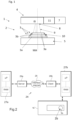
- Figure 1 illustrates schematically a manufacturing system 1 configured to carry out a method for additively manufacturing ophthalmic devices 2 each delimited by a respective external surface 10.
- the manufacturing system 1 is an additive system configured for manufacturing the ophthalmic devices 2 layer by layer, each layer 3 being formed by a volume of the predetermined material 11 at least partially polymerized and hardened.
- the manufacturing system 1 comprises an additive unit also called additive manufacturing module, and here formed by an inkjet printer 4 which is configured for projecting volumes of at least one predetermined material in the shape of droplets.
- the at least one predetermined material is suitable for manufacturing ophthalmic devices 2, such as a liquid resin for making eyeglasses.
- the inkjet printer 4 comprises one or a plurality of inkjet print heads 6i having each a plurality of nozzles 8 from which the predetermined material is projected in jets of droplets 9.
- the inkjet printer 4 further comprises at least one curing device 11 including for instance an irradiation source configured for performing curing steps.
- the curing device 11 is able to cure the droplets of material previously deposited by the nozzles 8.
- the inkjet printer 4 may further comprise a command and control unit 7 including system elements configured to run a computer program including instructions configured to implement at least some steps of the additive manufacturing method according to the disclosure for manufacturing the ophthalmic device 2.
- the command and control unit 7 may be configured to command and control activation and/or deactivation of each nozzle 8 and also each nozzle firing frequency if any.
- the nozzle firing frequency can be variable or fixed.
- the nozzle firing frequency may depend at least on geometrical characteristics of the ophthalmic device 2 to be manufactured and/or on the location, including for instance tilting and radial shifting relative to a manufacturing axis MA, of the print head(s).
- the inkjet printer 4 is here located on an upper side of a support member 5 and is configured to build core layers 3a and edge layers 3b at peripheral junctions between adjacent core layers, thus forming the layers 3 on the support member 5.
- the edge layers 3b can be able to form a major part of this external surface 10.
- the command and control unit 7 may be configured to locate the print head(s) 6i at a distance value selected among a plurality of distance values from the support member 5.
- the distance value is comprised between a minimum height according to which the predetermined material is able to forms droplets and a maximum height according to which the droplets predetermined material are deposited accurately on the support member 5.
- the support member 5 can be able to rotate around a rotation axis corresponding to the manufacturing axis MA and the print head(s) 6i and the support member 5 can be able to be inclined one relative to each other and/or the print head(s) 6i can be able to be inclined relative to the manufacturing axis MA.
- command and control unit 7 may also be configured to command and control a tilt angle of the print head(s) 6i and the support member one 5 one relative to each other, and a rotation speed of the support member 5 around the manufacturing axis MA.
- command and control unit 7 may be configured to command and control a print resolution of the print head(s) 6i, which comprises a process resolution corresponding to an angular resolution which is defined at least as a function of nozzles firing frequency, and the print head resolution as defined above.
- command and control unit 7 may be configured to provide to the print head(s) 6i a manufacturing file or parameters from this file including geometrical characteristics representative of the core layers 3a and edge layers 3b of the ophthalmic device 2, thus defining a so-called sliced ophthalmic device.
- the parameters of the manufacturing file may comprise a plurality of images each representative of a voxel distribution, or of a droplets distribution.
- the images determine the activated and deactivated nozzles 8 of the print head(s) 6i.
- the images can be determined thanks to at least one mathematical function defining the "shape" of the staircase which is to be filled.
- Each core layer 3a and/or each edge layer 3b can thus be defined by one or a plurality of images, depending on the geometrical characteristics of the layer as such and/or on core print properties and/or on edge print properties and/or on the print resolution and/or on the process resolution defined above.
- the core print properties may comprise a core ink material and/or a core drop density and/or a core drop volume and/or a core drop viscosity and/or a core drop speed ejection; and the edge print properties may comprise an edge ink material and/or an edge drop density and/or an edge drop volume and/or an edge drop viscosity and/or an edge drop speed ejection.
- Figure 2 shows a client-server communication interface 24 comprising for instance a so-called supplier side 29a and another, so-called client side 29b, and these two sides communicating via an internet interface 28.
- the supplier side comprises a server 29a linked to a data processing system or a command and control unit 27a of the same type as the command and control unit 7 disclosed in Figure 1 , this server 29a being configured to communicate with the internet interface 28.
- the client side 29b is configured to communicate with the internet interface 28, and is linked to a data processing system or a command and control unit 27b of the same type as that of the supplier side.
- command and control unit 27b on the client-side is linked to a manufacturing system 1b of the same type as that in Figure 1 for manufacturing an ophthalmic device 2b, using a layer 3b by layer 3b processing thanks to an inkjet printer as described above.
- the command and control unit 27b on the client-side is configured for receiving by a user some parameters about the ophthalmic device to be manufactured, about the inkjet printer and about the manufacturing method intended to be implemented for additively manufacturing the ophthalmic device 2b.
- the command and control unit 27b on the client-side using the internet 28 and server 29a interface, sends the data received to the command and control unit 27a on the supplier-side for the determination of a manufacturing file and operational parameters as described above.
- the command and control unit 27a on the supplier-side sends the manufacturing file and operational parameters to the command and control unit 27b on the client side.
- the command and control unit 27b on the client side is here configured to execute software for implementing the other steps of the method for additively manufacturing the ophthalmic device, that is to say layering and curing the layers of the ophthalmic device to be manufactured.
- the manufacturing system can be located on the supplier side so that the command and control unit on the supplier side is configured both to determine the manufacturing file and operational parameters and to additively manufacture the ophthalmic device.
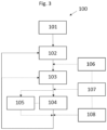
- Figure 3 is a block diagram showing the main steps of the method 100 for additively manufacturing an ophthalmic device 2 delimited by the external surface 10, the method 100 being carried out thanks to the manufacturing system 1 as described above.
- the method 100 comprises the following steps:
- the method 100 may further comprise the step of layering by inkjet printing 105 at least one third core layer at least partially onto the at least one second core layer.
- steps 104 and 105 of inkjet printing the at least one edge layer and the at least one third core layer can be performed at least partially simultaneously or at least partially successively.
- the at least one first core layer may have at least one first predetermined thickness
- the at least one second core layer may have at least one second predetermined thickness equal or different to the first predetermined thickness
- the at least one edge layer defines at least partially the external surface 10 of the ophthalmic device 2 and may have at least one third predetermined thickness lower than or equal to the at least one second predetermined thickness
- the at least one third core layer may have at least one fourth predetermined thickness equal or different to at least one of the first predetermined thickness, second predetermined thickness and third predetermined thickness.
- the method 100 may further comprise at least one of the following steps:
- the method 100 can be iterative.
- the steps 104 and/or 105 of inkjet printing the at least one edge layer and/or the at least one third core layer can be followed by the steps 102 and/or 103 of layering by inkjet printing further first and second core layers and/or the curing steps 106, 107 and 108.
- the step 104 of inkjet printing the at least one edge layer may comprise sub-steps of inkjet printing, at least partially simultaneously and/or at least partially successively, several sub-edge layers of similar or different thicknesses and arranged to be at least partially juxtaposed and/or at least partially superimposed, so that to obtain the at least one edge layer formed by the plurality of sub-edge layers.
- steps 102, 103 and 105 of inkjet printing the at least one first core layer, the at least one second core layer and the at least one third core layer may be performed with core print properties, similar or different one to each other, while the step 104 of inkjet printing the at least one edge layer may be performed with edge print properties at least partially distinct to the core print properties.
- the core print properties can be fixed or variable during inkjet printing the at least one first, second or third core layers; and the edge print properties can be fixed or variable during inkjet printing the at least one edge layer.
- the steps 102 and 103 and optionally 105 of inkjet printing the at least one first core layer, the at least one second core layer and also optionally the third core layer may be performed thanks to at least one core print head amongst the plurality of inkjet print heads 6i
- the steps 104 of inkjet printing the at least one edge layer may be performed thanks to at least one edge print head amongst the plurality of inkjet print heads 6i, distinct to the core print head(s).
- edge layer and a third core layer are inkjet printed simultaneously, that can be performed for instance thanks to different inkjet print heads 6i or by a single "hybrid" inkjet print head 6i configured to deliver both core print properties and edge print properties.
- Figure 4 shows a first example of a distribution of voxels according to the above described method, in order to inkjet print several layers 3 so as to obtain the ophthalmic device 2 having the external surface 10 without staircase.
- the layer “n-2" is here inkjet printed only as a core layer.
- the layer “n” is inkjet printed simultaneously as both a core layer 3a and a edge layer 3b around the core layer 3a, onto the layer “n-1".
- the layer "n" is cured.
- the edge layer 3b of the layer “n-1" has here a close ring shape.
- the layer “n” is obtained for instance thanks to the single image In including two different voxels distributions on the core and on the edge, also called hybrid distribution, while the layer “n-1" is obtained for instance thanks to several images In-1, one being dedicated to the core and the other to the edge.
- Figure 6 shows a second example of a distribution of voxels according to the above described method, in which the edge layer 3b is orderly distributed.
- Figure 6 focuses on the sub-edge layers 3b of both similar and different thicknesses deposited onto a first core layer and around a second core layer 3a.
- biggest droplets form a sub-edge layer directly onto the first core layer; in a second zone, smallest droplets form sub-edge layers opposite to the first core layer; and in a third zone, middle droplets form sub-edge layers located between the first and second zones.
- the sub-edge layers 3b shown in Figure 6 can be inkjet printed at least partially simultaneously and/or at least partially successively one to each other and/or thanks to a single or a plurality of print heads 6i.
- Figures 7 to 9 show different images having different voxels distribution which can be used to carry out the method according to the disclosure and in particular the core layers 3a and sub-edge layers 3b as shown in Figure 6 .
- the first core layer 3a is inkjet printed thanks to image I0.
- the second core layer 3a and a first sub-edge layer of the edge layer 3b, including the biggest droplets, are simultaneously inkjet printed thanks to image I1.
- the second core layer 3a and a second sub-edge layer of the edge layer 3b, including middle droplets, are simultaneously inkjet printed thanks to image I2.
- the second core layer 3a and a second sub-edge layer of the edge layer 3b, including the smallest droplets, are simultaneously inkjet printed thanks to image I3.
- the first core layer 3a is inkjet printed thanks to image I0; then, the second core layer 3a and the first sub-edge layer of the edge layer 3b having the biggest droplets are simultaneously inkjet printed thanks to image 11; then the second sub-edge layer of the edge layer 3b having middle droplets is inkjet printed thanks to image I2; then the second sub-edge layer of the edge layer 3b having the smallest droplets is inkjet printed thanks to image I3.
- the first core layer 3a is inkjet printed thanks to image I0; then, the second core layer 3a is inkjet printed thanks to image 11; then the first sub-edge layer of the edge layer 3b having the biggest droplets is inkjet printed thanks to image I2; then the second sub-edge layer of the edge layer 3b having middle droplets is inkjet printed thanks to image I3; then the second sub-edge layer of the edge layer 3b having the smallest droplets is inkjet printed thanks to image I4.
- curing steps can be carried out between steps of inkjet printing, as described above.
- Figure 10 shows detail of some of images illustrated in Figures 7 to 9 , based on different drop density A and drop volume B for instance for obtaining the sub-edges layer of the edge layer 3b.
- the method according to the disclosure it is possible to control accurately the inkjet printing at a peripheral junction between two or more successive layers, thus allowing to smooth the external surface of the ophthalmic device thanks to the dedicated at least one edge layer of a thickness lower than or equal to the thickness of the layer around which the at least one edge layer is deposited and optionally the layer onto which the at least one edge layer is also deposited.
- the method according to the disclosure may allow to provide, thanks to the technology of 3D-inkjet printing, an ophthalmic device having an external surface as closest as possible to a final external surface, with no stair step or with reduced stair steps at the external surface of the ophthalmic device.
- the method according to the disclosure allows to slice, or divide, layers which should usually be thicker, in a plurality of sublayers being thinness so as to discretize a pitch between these layers by depositing an accurate little amount of material at least on the edges and in order to obtain a curvature as closest as possible to the theoretical geometry, without any printing defaults such as staircases, which are indeed “smoothed” and/or "self-leveled”.
- the external surface to be obtained and more generally the geometrical characteristics of the ophthalmic device to be manufactured, can be adjusted, for instance slightly enlarged or extended, depending on the staircases to be “smoothed” and/or to be “self-leveled”.
- edge layers described above can be determined taking into the "self-level" properties of the material itself, so that there is no need, depending at least on geometrical characteristics and edge ink properties, to fill completely the volume corresponding to the staircase around the respective core layer.
Landscapes
- Engineering & Computer Science (AREA)
- Manufacturing & Machinery (AREA)
- Chemical & Material Sciences (AREA)
- Materials Engineering (AREA)
- Mechanical Engineering (AREA)
- Health & Medical Sciences (AREA)
- Ophthalmology & Optometry (AREA)
- Physics & Mathematics (AREA)
- Optics & Photonics (AREA)
Priority Applications (2)
| Application Number | Priority Date | Filing Date | Title |
|---|---|---|---|
| EP23307276.8A EP4574406A1 (de) | 2023-12-20 | 2023-12-20 | Verfahren zur generativen fertigung einer ophthalmischen vorrichtung und fertigungssystem zur durchführung solch eines verfahrens |
| PCT/EP2024/086658 WO2025132265A1 (en) | 2023-12-20 | 2024-12-16 | Method for additively manufacturing an ophthalmic device and manufacturing system configured to carry out such a method |
Applications Claiming Priority (1)
| Application Number | Priority Date | Filing Date | Title |
|---|---|---|---|
| EP23307276.8A EP4574406A1 (de) | 2023-12-20 | 2023-12-20 | Verfahren zur generativen fertigung einer ophthalmischen vorrichtung und fertigungssystem zur durchführung solch eines verfahrens |
Publications (1)
| Publication Number | Publication Date |
|---|---|
| EP4574406A1 true EP4574406A1 (de) | 2025-06-25 |
Family
ID=89573736
Family Applications (1)
| Application Number | Title | Priority Date | Filing Date |
|---|---|---|---|
| EP23307276.8A Pending EP4574406A1 (de) | 2023-12-20 | 2023-12-20 | Verfahren zur generativen fertigung einer ophthalmischen vorrichtung und fertigungssystem zur durchführung solch eines verfahrens |
Country Status (2)
| Country | Link |
|---|---|
| EP (1) | EP4574406A1 (de) |
| WO (1) | WO2025132265A1 (de) |
Citations (5)
| Publication number | Priority date | Publication date | Assignee | Title |
|---|---|---|---|---|
| US20040159978A1 (en) * | 2003-01-29 | 2004-08-19 | Nielsen Jeffrey A. | Methods and systems for producing an object through solid freeform fabrication by varying a concentration of ejected material applied to an object layer |
| US20050015173A1 (en) * | 2001-08-16 | 2005-01-20 | Hitoshi Ohmori | Rapid prototyping method and device using v-cad data |
| US20160101573A1 (en) * | 2013-06-07 | 2016-04-14 | Essilor International (Compagnie Générale d'Optique) | Process and machine for manufacturing an ophthalmic lens |
| US20180136632A1 (en) * | 2015-06-05 | 2018-05-17 | Canon Kabushiki Kaisha | Information processing apparatus and information processing method |
| EP3722073A1 (de) * | 2019-04-11 | 2020-10-14 | Luxexcel Holding B.V. | Verfahren zum drucken einer optischen komponente |
-
2023
- 2023-12-20 EP EP23307276.8A patent/EP4574406A1/de active Pending
-
2024
- 2024-12-16 WO PCT/EP2024/086658 patent/WO2025132265A1/en active Pending
Patent Citations (5)
| Publication number | Priority date | Publication date | Assignee | Title |
|---|---|---|---|---|
| US20050015173A1 (en) * | 2001-08-16 | 2005-01-20 | Hitoshi Ohmori | Rapid prototyping method and device using v-cad data |
| US20040159978A1 (en) * | 2003-01-29 | 2004-08-19 | Nielsen Jeffrey A. | Methods and systems for producing an object through solid freeform fabrication by varying a concentration of ejected material applied to an object layer |
| US20160101573A1 (en) * | 2013-06-07 | 2016-04-14 | Essilor International (Compagnie Générale d'Optique) | Process and machine for manufacturing an ophthalmic lens |
| US20180136632A1 (en) * | 2015-06-05 | 2018-05-17 | Canon Kabushiki Kaisha | Information processing apparatus and information processing method |
| EP3722073A1 (de) * | 2019-04-11 | 2020-10-14 | Luxexcel Holding B.V. | Verfahren zum drucken einer optischen komponente |
Also Published As
| Publication number | Publication date |
|---|---|
| WO2025132265A1 (en) | 2025-06-26 |
Similar Documents
| Publication | Publication Date | Title |
|---|---|---|
| JP6378932B2 (ja) | 三次元構造物の形成装置および形成方法 | |
| EP3482914B1 (de) | Verfahren zum bestimmen der neigung der achsen einer maschine mit fünf oder mehr achsen zum herstellen von objekten durch additive fertigung, system zum herstellen von objekten nach diesem verfahren | |
| CN113681898B (zh) | 三维物体打印方法、数据处理装置及计算机设备 | |
| EP3589477B1 (de) | 3d-druck mittels sprühformung | |
| CA2229531A1 (en) | Rapid prototyping method | |
| JP2017507050A (ja) | 3次元プリンタ | |
| EP3393114B1 (de) | Verfahren zur verminderung von farbkonturen von 3d-objekten nach innen | |
| WO2019194795A1 (en) | Three dimensional (3d) printing | |
| CN109094022B (zh) | 3d打印设备及方法 | |
| CN107211071B (zh) | 用于生成三维物体的装置、方法和可读介质 | |
| KR102503006B1 (ko) | 안경 렌즈 제조 시스템 | |
| KR20180026321A (ko) | 플랫폼 이동형 3d 인쇄 방법 | |
| TWI711532B (zh) | 彩色3d物件的顏色補償方法 | |
| US20190337245A1 (en) | Flexible tooling system and method for manufacturing of composite structures | |
| CN109878090A (zh) | 切层方法、切层数据的更新方法及打印系统 | |
| WO2025132265A1 (en) | Method for additively manufacturing an ophthalmic device and manufacturing system configured to carry out such a method | |
| JP2018065366A (ja) | レーザーを用いた3dプリンタの走査軌跡範囲を設定する方法 | |
| CN114834045A (zh) | 一种喷墨3d打印建模与补偿方法及闭环打印系统 | |
| EP4385735A1 (de) | Verfahren zur generativen fertigung einer ophthalmischen vorrichtung und fertigungssystem zur durchführung solch eines verfahrens | |
| US20220111610A1 (en) | Method for printing a multifocal lens | |
| US20240051219A1 (en) | Systems and methods of offset surface deposition in additive fabrication | |
| WO2026104511A1 (en) | Method for additively manufacturing an ophthalmic device and manufacturing system configured to carry out such a method | |
| CN108656521A (zh) | 立体物造型装置及其控制程序、立体物造型方法 | |
| US20220072859A1 (en) | Printing head for non-cartesian inkjet printing | |
| US12318993B2 (en) | Method and system for reducing waviness in three-dimensional printing |
Legal Events
| Date | Code | Title | Description |
|---|---|---|---|
| PUAI | Public reference made under article 153(3) epc to a published international application that has entered the european phase |
Free format text: ORIGINAL CODE: 0009012 |
|
| STAA | Information on the status of an ep patent application or granted ep patent |
Free format text: STATUS: THE APPLICATION HAS BEEN PUBLISHED |
|
| AK | Designated contracting states |
Kind code of ref document: A1 Designated state(s): AL AT BE BG CH CY CZ DE DK EE ES FI FR GB GR HR HU IE IS IT LI LT LU LV MC ME MK MT NL NO PL PT RO RS SE SI SK SM TR |
|
| STAA | Information on the status of an ep patent application or granted ep patent |
Free format text: STATUS: REQUEST FOR EXAMINATION WAS MADE |
|
| 17P | Request for examination filed |
Effective date: 20251222 |