EP4574475A1 - Wärmetauscher - Google Patents
Wärmetauscher Download PDFInfo
- Publication number
- EP4574475A1 EP4574475A1 EP23218957.1A EP23218957A EP4574475A1 EP 4574475 A1 EP4574475 A1 EP 4574475A1 EP 23218957 A EP23218957 A EP 23218957A EP 4574475 A1 EP4574475 A1 EP 4574475A1
- Authority
- EP
- European Patent Office
- Prior art keywords
- tubes
- fluid
- manifold
- heat exchanger
- channel
- Prior art date
- Legal status (The legal status is an assumption and is not a legal conclusion. Google has not performed a legal analysis and makes no representation as to the accuracy of the status listed.)
- Pending
Links
Images


Classifications
-
- F—MECHANICAL ENGINEERING; LIGHTING; HEATING; WEAPONS; BLASTING
- F28—HEAT EXCHANGE IN GENERAL
- F28D—HEAT-EXCHANGE APPARATUS, NOT PROVIDED FOR IN ANOTHER SUBCLASS, IN WHICH THE HEAT-EXCHANGE MEDIA DO NOT COME INTO DIRECT CONTACT
- F28D7/00—Heat-exchange apparatus having stationary tubular conduit assemblies for both heat-exchange media, the media being in contact with different sides of a conduit wall
- F28D7/16—Heat-exchange apparatus having stationary tubular conduit assemblies for both heat-exchange media, the media being in contact with different sides of a conduit wall the conduits being arranged in parallel spaced relation
- F28D7/1684—Heat-exchange apparatus having stationary tubular conduit assemblies for both heat-exchange media, the media being in contact with different sides of a conduit wall the conduits being arranged in parallel spaced relation the conduits having a non-circular cross-section
- F28D7/1692—Heat-exchange apparatus having stationary tubular conduit assemblies for both heat-exchange media, the media being in contact with different sides of a conduit wall the conduits being arranged in parallel spaced relation the conduits having a non-circular cross-section with particular pattern of flow of the heat exchange media, e.g. change of flow direction
-
- F—MECHANICAL ENGINEERING; LIGHTING; HEATING; WEAPONS; BLASTING
- F28—HEAT EXCHANGE IN GENERAL
- F28D—HEAT-EXCHANGE APPARATUS, NOT PROVIDED FOR IN ANOTHER SUBCLASS, IN WHICH THE HEAT-EXCHANGE MEDIA DO NOT COME INTO DIRECT CONTACT
- F28D1/00—Heat-exchange apparatus having stationary conduit assemblies for one heat-exchange medium only, the media being in contact with different sides of the conduit wall, in which the other heat-exchange medium is a large body of fluid, e.g. domestic or motor car radiators
- F28D1/02—Heat-exchange apparatus having stationary conduit assemblies for one heat-exchange medium only, the media being in contact with different sides of the conduit wall, in which the other heat-exchange medium is a large body of fluid, e.g. domestic or motor car radiators with heat-exchange conduits immersed in the body of fluid
- F28D1/04—Heat-exchange apparatus having stationary conduit assemblies for one heat-exchange medium only, the media being in contact with different sides of the conduit wall, in which the other heat-exchange medium is a large body of fluid, e.g. domestic or motor car radiators with heat-exchange conduits immersed in the body of fluid with tubular conduits
- F28D1/0408—Multi-circuit heat exchangers, e.g. integrating different heat exchange sections in the same unit or heat exchangers for more than two fluids
- F28D1/0461—Combination of different types of heat exchanger, e.g. radiator combined with tube-and-shell heat exchanger; Arrangement of conduits for heat exchange between at least two media and for heat exchange between at least one medium and the large body of fluid
-
- F—MECHANICAL ENGINEERING; LIGHTING; HEATING; WEAPONS; BLASTING
- F28—HEAT EXCHANGE IN GENERAL
- F28D—HEAT-EXCHANGE APPARATUS, NOT PROVIDED FOR IN ANOTHER SUBCLASS, IN WHICH THE HEAT-EXCHANGE MEDIA DO NOT COME INTO DIRECT CONTACT
- F28D7/00—Heat-exchange apparatus having stationary tubular conduit assemblies for both heat-exchange media, the media being in contact with different sides of a conduit wall
- F28D7/0066—Multi-circuit heat-exchangers, e.g. integrating different heat exchange sections in the same unit or heat-exchangers for more than two fluids
- F28D7/0075—Multi-circuit heat-exchangers, e.g. integrating different heat exchange sections in the same unit or heat-exchangers for more than two fluids with particular circuits for the same heat exchange medium, e.g. with the same heat exchange medium flowing through sections having different heat exchange capacities or for heating or cooling the same heat exchange medium at different temperatures
-
- F—MECHANICAL ENGINEERING; LIGHTING; HEATING; WEAPONS; BLASTING
- F28—HEAT EXCHANGE IN GENERAL
- F28D—HEAT-EXCHANGE APPARATUS, NOT PROVIDED FOR IN ANOTHER SUBCLASS, IN WHICH THE HEAT-EXCHANGE MEDIA DO NOT COME INTO DIRECT CONTACT
- F28D7/00—Heat-exchange apparatus having stationary tubular conduit assemblies for both heat-exchange media, the media being in contact with different sides of a conduit wall
- F28D7/0066—Multi-circuit heat-exchangers, e.g. integrating different heat exchange sections in the same unit or heat-exchangers for more than two fluids
- F28D7/0083—Multi-circuit heat-exchangers, e.g. integrating different heat exchange sections in the same unit or heat-exchangers for more than two fluids with units having particular arrangement relative to a supplementary heat exchange medium, e.g. with interleaved units or with adjacent units arranged in common flow of supplementary heat exchange medium
-
- F—MECHANICAL ENGINEERING; LIGHTING; HEATING; WEAPONS; BLASTING
- F28—HEAT EXCHANGE IN GENERAL
- F28F—DETAILS OF HEAT-EXCHANGE AND HEAT-TRANSFER APPARATUS, OF GENERAL APPLICATION
- F28F1/00—Tubular elements; Assemblies of tubular elements
- F28F1/02—Tubular elements of cross-section which is non-circular
- F28F1/025—Tubular elements of cross-section which is non-circular with variable shape, e.g. with modified tube ends, with different geometrical features
-
- F—MECHANICAL ENGINEERING; LIGHTING; HEATING; WEAPONS; BLASTING
- F25—REFRIGERATION OR COOLING; COMBINED HEATING AND REFRIGERATION SYSTEMS; HEAT PUMP SYSTEMS; MANUFACTURE OR STORAGE OF ICE; LIQUEFACTION SOLIDIFICATION OF GASES
- F25B—REFRIGERATION MACHINES, PLANTS OR SYSTEMS; COMBINED HEATING AND REFRIGERATION SYSTEMS; HEAT PUMP SYSTEMS
- F25B39/00—Evaporators; Condensers
-
- F—MECHANICAL ENGINEERING; LIGHTING; HEATING; WEAPONS; BLASTING
- F28—HEAT EXCHANGE IN GENERAL
- F28D—HEAT-EXCHANGE APPARATUS, NOT PROVIDED FOR IN ANOTHER SUBCLASS, IN WHICH THE HEAT-EXCHANGE MEDIA DO NOT COME INTO DIRECT CONTACT
- F28D1/00—Heat-exchange apparatus having stationary conduit assemblies for one heat-exchange medium only, the media being in contact with different sides of the conduit wall, in which the other heat-exchange medium is a large body of fluid, e.g. domestic or motor car radiators
- F28D1/02—Heat-exchange apparatus having stationary conduit assemblies for one heat-exchange medium only, the media being in contact with different sides of the conduit wall, in which the other heat-exchange medium is a large body of fluid, e.g. domestic or motor car radiators with heat-exchange conduits immersed in the body of fluid
- F28D1/04—Heat-exchange apparatus having stationary conduit assemblies for one heat-exchange medium only, the media being in contact with different sides of the conduit wall, in which the other heat-exchange medium is a large body of fluid, e.g. domestic or motor car radiators with heat-exchange conduits immersed in the body of fluid with tubular conduits
- F28D1/0408—Multi-circuit heat exchangers, e.g. integrating different heat exchange sections in the same unit or heat exchangers for more than two fluids
- F28D1/0417—Multi-circuit heat exchangers, e.g. integrating different heat exchange sections in the same unit or heat exchangers for more than two fluids with particular circuits for the same heat exchange medium, e.g. with the heat exchange medium flowing through sections having different heat exchange capacities or for heating/cooling the heat exchange medium at different temperatures
-
- F—MECHANICAL ENGINEERING; LIGHTING; HEATING; WEAPONS; BLASTING
- F28—HEAT EXCHANGE IN GENERAL
- F28F—DETAILS OF HEAT-EXCHANGE AND HEAT-TRANSFER APPARATUS, OF GENERAL APPLICATION
- F28F1/00—Tubular elements; Assemblies of tubular elements
- F28F1/10—Tubular elements and assemblies thereof with means for increasing heat-transfer area, e.g. with fins, with projections, with recesses
- F28F1/12—Tubular elements and assemblies thereof with means for increasing heat-transfer area, e.g. with fins, with projections, with recesses the means being only outside the tubular element
- F28F1/126—Tubular elements and assemblies thereof with means for increasing heat-transfer area, e.g. with fins, with projections, with recesses the means being only outside the tubular element consisting of zig-zag shaped fins
Definitions
- the present invention relates to a heat exchanger. More specifically, the present invention relates to a multifunctional heat exchanger for a motor vehicle that is able to withstand high fluid pressures.
- a vehicle is provided with several heat exchangers for example, an internal heat exchanger, an evaporator, a condenser, a water condenser (WCDS), etc.
- the evaporator and the condenser are part of an air-conditioning (AC) loop or a part of HVAC system.
- AC air-conditioning
- IHX is used to transfer heat between the low side pressure and the high pressure flow circuits. Its function is to improve system performance by further sub-cooling the refrigerant being supplied to the evaporator through the refrigerant control device.
- a conventional heat exchanger typically includes a pair of manifolds, including a first manifold and a second manifold, configured at two opposite sides of the heat exchanger, and a heat exchanger core arranged between the pair of manifolds.
- the heat exchanger core is formed of a plurality of flat tubes (hereinafter, also referred to as tubes for simplicity) and fins arranged between outer surfaces of the adjacent tubes.
- Each tube has two opposite open ends which are inserted into respective tube insertion slots of a first header and a second header of the respective first manifold and the second manifold.
- Each of the first header and the second header in conjunction with a corresponding first tank and second tank define the first manifold and the second manifold for receiving and distributing the fluid/coolant to the tubes.
- One or more of the fluid/coolants flow between the first manifold to the second manifold through the plurality of tubes and the other fluid/air flows around and in a space between the tubes to enable heat exchange between the fluids.
- the heat exchanger has to be adapted accordingly.
- the high-pressure fluid imposes additional design constrains on the heat exchanger as the high pressure of the fluid necessitates higher mechanical resistance of heat exchanger components.
- efficiency requirements pose further demands on the heat exchanger.
- the existing heat exchangers are not capable to operate efficiently for the fluid/coolant operate at the high pressure, which can be up to 260 bar on the low-pressure side and up to 360 bar on the high-pressure side.
- the invention concerns, inter alia, a heat exchanger for a motor vehicle comprising: a first manifold; a second manifold configured spaced apart from the first manifold; and a plurality of tubes fluidically connected between the first manifold and the second manifold, the tubes being configured to enable circulation of at least one of a first fluid and a second fluid between the first manifold and the second manifold; wherein the plurality of tubes comprises one or more sets of first tubes and one or more sets of second tubes, wherein the one or more sets of first tubes and the one or more sets of second tubes are arranged one above another in an alternate manner in at least one row such that at least a portion of neighboring tubes of the corresponding set of first tubes and the set of second tubes abut each other; wherein the plurality of tubes comprises one or more sets of third tubes, the third tubes being arranged one above another in an alternate manner in at least one row such that at least a portion of neighboring tubes of the corresponding set of second tubes and the set of third tubes abut with
- the third tubes are fluidly insulated from the third fluid.
- the housing comprises at least a first housing wall and a second housing wall, the walls extending in parallel with respect to each-other, wherein the tubes are arranged in-between said walls, so that an inner face of the first housing wall and an inner face of the second housing wall are facing said tubes.
- either of the first housing wall and/or the second housing wall at least partially overlaps the second tubes and the third tubes, so that the heat exchange between the third fluid and at least the first fluid is enabled.
- the first housing wall and/or the second housing wall overlaps the second tubes, the second tubes and the third tubes entirely, whereas the heat exchange between the third fluid and at least the first fluid is enabled.
- the circuit for the third fluid is formed by fluid tight connection between the housing walls, and two tubes of the plurality of tubes, wherein the inner portions of the housing walls are in contact with the shorter sides of the tubes, wherein the tubes, are substantially perpendicular with respect to the housing walls.
- the first manifold comprises a first channel and a second channel, the channels being fluidly connected to at least a first block, wherein the second manifold comprises a third channel and at least a fourth channel, wherein the channels are fluidly connected to at least a second block, and a third block, wherein the third block is juxtaposed with respect to the second block on the second manifold.
- the third tubes of the plurality of tubes form an internal heat exchanger section whereas the first tubes and the second tubes of said plurality of tubes form a chiller section.
- the heat exchanger further comprises an expansion device, wherein said expansion device is fluidly connected at least with the second manifold, wherein the expansion device converts the first fluid into the second fluid.
- the first fluid is directed from the first block through the first channel of the first manifold into the third tubes, the third tubes being fluidly connected with the second manifold, wherein the first fluid is transferred through the third channel to the second block, the second block being fluidly connected with the expansion device into which the first fluid is introduced, wherein the expansion device is further fluidly connected with the third block into which the second fluid is introduced, wherein the third block is fluidly connected with the fourth channel, so that the second fluid is introduced into the second manifold, wherein said fourth channel is fluidly connected at least with the second tubes, the second tubes being configured to fluidly connect the second manifold and the first manifold, wherein the second fluid is further directed into the first tubes via the second channel of the first manifold, so that the U-flow of the second fluid is provided, wherein the first tubesare fluidly connected with the third channel, wherein the third channel is further fluidly connected with the third tubes, so that the second fluid flows through said third tubes towards the second channel, wherein the second channel is fluidly connected with the or
- the third tubes of the plurality of tubes form an internal heat exchanger section whereas the first tubes and the second tubes of said plurality of tubes form a water gas cooler section.
- the second fluid is directed from the first block through the first channel of the first manifold into the third tubes, the third tubes being fluidly connected with the second manifold, wherein the second fluid egresses from the heat exchanger through the second block being fluidly connected to the third channel.
- the first fluid egresses into the heat exchanger through the third block, wherein the third block is fluidly connected with the fourth channel, so that the first fluid is introduced into the second manifold, wherein said fourth channel is fluidly connected at least with the second tubes, the second tubes being configured to fluidly connect the second manifold and the first manifold, wherein the second fluid is further directed into the first tubes via the second channel of the first manifold, so that the U-flow of the first fluid is provided, wherein the first tubes are fluidly connected with the third channel, wherein the third channel is further fluidly connected with the third tubes, so that the first fluid flows through said third tubes towards the second channel, wherein the second channel is fluidly connected with the orifice in the first block, wherein said orifice in the first block is configured to provide an egress of the first fluid from the heat exchanger.
- the heat exchanger further comprising a first spigot for ingress of the third fluid into the housing, and a second spigot for egress of the third fluid from the housing.
- the housing comprises at least one return channel configured to provide a U-flow for the third fluid.
- the return channel is in a form of protrusion protruding outwardly with respect to the plurality of tubes, so that a gap is formed between the inner portions of the housing walls and the shorter sides of the tubes.
- each set of tubes of the one or more sets of first tubes and the one or more sets of second tubes or third tubes comprises at least two juxtaposed tubes.
- each tube of the plurality of tubes comprises an intermediate flat tube section, two opposite tube end sections, and two tube bent sections located between the intermediate flat tube section and the two respective opposite tube end sections.
- the total length of the tube end sections is at least ten percent of length of the third tubes, wherein the length is measured in parallel with respect to the axis of elongation of the tubes.
- the general plane formed by the intermediate flat tube section is offset with respect to the general plane formed by at least one secondary flat tube section of the same third tube.
- two general planes of the secondary flat tube sections formed on the opposite sides of the intermediate flat tube section of the third tube are coplanar.
- the consecutive third tubes are interlaced with fins, the fins extending along the neighboring intermediate flat tube sections of said third tubes.
- the consecutive first and second tubes are interlaced with turbulators, the turbulators extending along the neighboring intermediate flat tube sections of said first and second tubes .
- the first manifold includes a first header plate, a first cover, and one or more first internal plates configured between the first header plate and the first cover.
- the second manifold includes a second header plate, a second cover, and one or more second internal plate configured between the second header plate and the second cover.
- the subject-matter of the present invention is, among others, a heat exchanger for a motor vehicle. More specifically, the present invention discloses a simple, light, and cost efficient heat exchanger that is able to withstand high fluid pressures, which can be up to 260 bar on the low-pressure side (LP) and up to 360 bar on the high-pressure side (HP), for high-pressure systems.
- the heat exchanger is adapted to exchange heat between refrigerants from low pressure side and high pressure side of a cooling loop to increase efficiency of the cooling loop of the air conditioning system and/or cooling system.
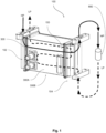
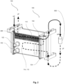
- a heat exchanger 100 being the subject-matter of the invention may comprise a first manifold 102, a second manifold 104 configured spaced apart on two opposite sides of a heat exchanger core 150.
- the core 150 is configured to fluidically connect the first manifold 102 and the second manifold 104.
- the heat exchanger core 150 may comprise a plurality of tubes 112, 114 and 115 fluidically connected between the first manifold 102 and the second manifold 104 to circulate at least one of a first fluid and a second fluid between the first manifold 102 and the second manifold 104.
- the first manifold 102 comprises at least one channel, such as channels 106a, 106b
- the second manifold 104 comprises at least one channel, such as channels 108a and 108b.
- the first fluid and/or the second fluid can be a natural refrigerant such as, but not limited to, R744 (CO2) or R290 (propane).
- first fluid and second fluid may refer not only to two completely different fluids having, for example, different chemical composition, but also to substantially the same fluid having different properties.
- first fluid HP
- second fluid LP
- third fluid COOL
- COOL coolant
- the plurality of tubes 112, 114, 115 may comprise one or more sets of first tubes 112, one or more sets of second tubes 114 and one or more sets of third tubes 115.
- the one or more sets of first tubes 112 and the one or more sets of second tubes 114 are arranged one above another in an alternate manner in at least one row such that at least a portion of neighboring tubes of the corresponding set of first tubes 112 and the set of second tubes 114 abut with each other.
- one or more sets of second tubes 114 and the one or more sets of third tubes 115 are arranged one above another in an alternate manner in at least one row such that at least a portion of neighboring tubes of the corresponding set of second tubes 114 and the set of third tubes 115 abut with each other.
- the plurality of tubes 112, 114, 115 may be extruded tubes with micro ports, i.e., the plurality of tubes 112, 114, 115 can include micro channels extending along lengths of the tubes.
- extreme upper and lower tubes of each set of tubes 112, 114, 115 i.e. external tubes of each stack of tubes 112, 114, 115, of the core 150 can be a blind tubes to avoid transfer of fluid through the tubes which are not in contact with another tube of adjacent set of tubes.
- each set of tubes of the one or more sets of first tubes 112, the one or more sets of second tubes 114 and one or more sets of third tubes 115 comprises two tubes.
- the spacers 118 are provided in a gap between the two tubes of each sets of tubes 112, 114,115.
- the spacers/fillers 118 between tubes of each set of tubes 112, 114, 115 are adapted to ensure contact between the tubes 112 and 114 or 114 and 115.
- the spacers/fillers 118 between each set of tubes 112, 114, 115 can reinforce the corresponding set of tubes 112, 114, 115.
- the spacers 118 can be of different shapes such as but not limited to corrugated, rectangular, triangular, trapezoidal, and the like.
- the spacers 118 can disrupt the air flowing across the core 150 in order to improve the heat exchange of air with the first and/or the second fluid (LP)s flowing through the tubes 112, 114, 115.
- Each tube of the plurality of tubes 112, 114, 115 may include an intermediate flat tube section 116a, two opposite tube end sections 116c, and two tube bend sections 116b between the intermediate flat tube section 116a and the two opposite tube end sections 116c.
- Each of the tube bend sections 116b comprises two opposite turns connected to the respective end of the intermediate flat tube section 116a and the tube end section 116c, which enables offset arrangement of the intermediate flat tube section 116a with respect to the tube end sections 116c.
- one or more sets of second tubes 114 or one or more sets of the third tubes are configured with concavities of the tubes 112, 114, 115 facing each other the intermediate flat tube sections 116a of the two tubes 112, 114, 115 extend substantially in a parallel and spaced manner to each other and the tube end sections 116c are stacked on each other.
- the sets of second tubes 114 or the third sets of tubes 115 are configured to be received in the corresponding single tube slot 126/128 of the manifolds 102 and 104.
- this arrangement of the tubes end sections 116c of the two tubes in single slot 126/128 of the respective manifold 102/104 help to mechanically strengthen the proposed heat exchanger by reducing the number of required slots 126/128 in the manifolds 102 and 104 and increases a gap between two adjacent slots 126/128 of the manifold 102/104 in comparison to number of slots required and a gap between two adjacent slots in the conventional heat exchanger with same number of flat tubes.
- One or more sets of first tubes 112 and the one or more sets of second tubes 114 are arranged one above another in alternate manner such that the intermediate flat tube sections 116a of neighboring tubes of the corresponding set of first tubes 112 and the set of second tubes 114 abut with each other.
- This contact between the intermediate flat tube sections 116a of the one or more sets of first tubes 112 and the one or more sets of second tubes 114 allows heat exchange between the fluids, such as the first fluid (HP) and/or the second fluid (LP), flowing through the one or more sets of first tubes 112 and the one or more sets of second tubes 114.
- one or more sets of second tubes 114 and the one or more sets of third tubes 115 may be arranged one above another in alternate manner such that the intermediate flat tube sections 116a of neighboring tubes 114, 115 of the corresponding set of second tubes 114 and the set of third tubes 115 abut with each other.
- This contact between the intermediate flat tube sections 116a of the one or more sets of second tubes 114 and the one or more sets of third tubes 115 allows heat exchange between the fluids, such as the first fluid (HP) and/or the second fluid (LP), flowing through the one or more sets of second tubes 114 and the one or more sets of third tubes 115.
- the first fluid (HP) and the second fluid (LP) can be same refrigerant fluid.
- first fluid (HP) and the second fluid (LP) can be different refrigerant fluids.
- spacers 118 or metallic foils such as aluminum foils, can be provided between the two adjacent sets of tubes, such as between the sets of first tubes 112 and the sets of second tubes 114.
- the neighboring tubes 112, 114, 115 of the sets of first tubes 112 and the sets of second tubes 114 can be in contact with each other through the spacers 118 or metallic foils indirectly to exchange heat between the fluids flowing though the set of first tubes 112 and the set of second tubes 114.
- the sets of first tubes 112 can be connected to odd number of slots 126/128 of the manifolds 102 and 104, and the sets of second tubes 114 can be connected to even number of slots 126/128 of the manifolds 102 and 104 or vice versa.
- the fist fluid can circulate though the sets of first tubes 112 and the second fluid (LP) can circulate through the sets of second tubes 114 or vice versa.
- the sets of second tubes 114 can be connected to odd number of slots 126/128 of the manifolds 102 and 104, and the sets of third tubes 115 can be connected to even number of slots 126/128 of the manifolds 102 and 104 or vice versa.
- the first fluid (HP) can circulate though the sets of second tubes 114 and the second fluid (LP) can circulate through the sets of third tubes 115 or vice versa.
- the first manifold 102 may comprise a first header plate 120, a first cover 124.
- the first header plate 120 is configured to receive the tubes 112, 114, 115 and to be attached to the first cover 124.
- the first manifold 102 may comprise one or more first internal plates 122 arranged between the first header plate 120 and the first cover 124.
- the internal plates 122 may be regarded as spacers with openings which allow the first fluid (HP) and or second fluid (LP) circulation in the heat exchanger 100.
- the first header plate 120 can include a plurality slots 126, and the first inner plates 122 can also include a plurality of slots 127 corresponding to the slots 126 of the first header plate 120.
- the first cover 124 can include two channels 106a and 106b on an outer side of the first cover 124 and extending along the length of the first cover 124.
- the second manifold 104 may comprise a second header plate 130, and a second cover 134.
- the second header plate 130 is configured to receive the tubes 112, 114, 115 and to be attached to the second cover 134.
- the second manifold 104 may comprise one or more second internal plates 132 configured between the second header plate 130 and the second cover 134.
- the internal plates 132 may be regarded as spacers with openings which allow the first fluid (HP) and or second fluid (LP) circulation in the heat exchanger 100.
- the second header plate 130 may comprise a plurality slots 126, and the second inner plates 132 can also include a plurality of slots 127 corresponding to the slots 126 of the second header plate 130.
- the second cover 134 can include two channels 108a and 108b on an outer side of the second cover 134 and extending along the length of the second cover 134.
- the third tubes 115 may be arranged one above another in an alternate manner in at least one row such that at least a portion of neighboring tubes of the corresponding set of second tubes 114 and the set of third tubes 115 abut with each other. It is to be noted that the third tubes 115 may be structurally the same as the second tubes 114 yet said tubes 114, 115 may have different function.
- the second tubes 114 and the third tubes 115 exchange the heat mainly with the third fluid (COOL), whereas the first tubes 112 may exchange the heat between the first fluid HP and the second fluid LP.
- the conduit for the third fluid (COOL) which would allow the heat transfer between the third fluid (COOL) and at least second fluid (LP), the heat exchanger 100 may further comprise a housing 300.
- the housing 300 may be configured to at least partially encapsulate the second tubes 112 and at least the third tubes 115 to enable circulation of at least a third fluid. It means that not all tubes of the plurality of tubes 112, 114, 115 must be contained in the coolant circuit. From the production point of view it is easier to encapsulate all the tubes, namely the first tubes 112, the second tubes 114 and the third tubes 115, yet in one of the embodiments only the second tubes 114 and the third tubes 115 may be in contact with the third fluid (COOL) to exchange the heat therewith.
- COOL third fluid
- the third fluid (COOL) rinses the outer faces of the second tubes 114 and/or the third tubes 115.
- the first tubes 112 may thus be encapsulated in the zone with no third fluid (COOL).
- the first tubes 112 may be fluidly insulated from the third fluid (COOL). This provides, for example, a physical barrier against moisture and debris, which in general increase the corrosion resistance of the heat exchanger 100.
- the housing 300 may comprise at least a first housing wall 300a and a second housing wall 300b.
- the walls 300a, 300b may be essentially a flat metallic plates.
- the walls 300a, 300b may extend in parallel with respect to each-other so that the tubes 112, 114, 115 are arranged in-between said walls 300a, 300b, so that an inner face of the first housing wall 300a and an inner face of the second housing wall 300b are facing said tubes 112, 114, 115.
- COOL third fluid
- first housing wall 300a and/or the second housing wall 300b may at least partially overlap the second tubes 114 and the third tubes 115, so that the heat exchange between the third fluid (COOL) and at least the second fluid (LP) is enabled.
- first housing wall 300a and/or the second housing wall 300b overlap the first tubes 112, the second tubes 114 and the third tubes 115 entirely.
- heat exchange between the third fluid (COOL) and at least the second fluid (LP) may be enabled as well as the heat exchanger between the first fluid (HP) and the third fluid (COOL).
- the circuit for the third fluid may be formed by fluid tight connection between the housing walls 300a, 300b, and two tubes of the plurality of tubes 112, 114, 115. It should be noted that the inner portions of the housing walls 300a, 300b may in contact with the shorter sides of the tubes 112, 114, 115.
- the shorter sides of the tubes are two juxtaposed walls connecting two flat surfaces on both sides of the tubes 112. 114, 115.
- the tubes 112, 114, 115, or rather, the flat surfaces thereof may be substantially perpendicular with respect to the housing walls 300a, 300b.
- the housing walls 300a, 300b may be fixed to the tubes 112, 114, 115 in a fluid- tight manner to provide the conduit for the third fluid (COOL).
- the inner faces of the housing walls 300a 300b may be brazed to the shorter sides of the tubes forming a set of second tubes 114 and third tubes 115, or alternatively, the inner faces of the housing walls 300a 300b may be brazed to the shorter sides of the tubes forming a first set of tubes 112, the second set of tubes 114 and the set of third set of tubes 155.
- one of the second tubes 114 may be a third housing wall 300c and one of the third tubes 115 may be a fourth housing wall 300d.
- one of the first tubes 112, may be the third housing wall 300c and one of the third tubes 115 may be a fourth housing wall 300d.
- the heat exchanger 100 may comprise at least one U-pass 300f.
- the U-pass 300f may be in form of the protrusion on at least one of the housing walls 300a, 300b, so that the third fluid (COOL) rinses the third tubes 115 first, and then the second tubes 114.
- the embodiment wherein third fluid (COOL) rinses the second tubes 114 first, and then the second tubes 115 is also envisaged.
- the first manifold 102 may comprise a first channel 102A and a second channel 102B.
- the channels 102A, 102B may be fluidly connected to at least a first block 140, wherein the second manifold 104 comprises a third channel 104A and at least a fourth channel 104B, wherein the channels 104A, 104B are fluidly connected to at least a second block 142, and a third block 144, wherein the third block 144 is juxtaposed with respect to the second block 142 on the second manifold 104.
- the first tubes 112 of the plurality of tubes 112, 114, 115 may form an internal heat exchanger section 990, also called IHX section.
- the first tubes 112 forming the IHX section 990 may be exposed to the environment or rather, the ambience in vehicle compartment, or it can be encapsulated by the housing 300.
- the second tubes 114 and the third tubes 115 of said plurality of tubes 112, 114, 115 may form a chiller section 991.
- the chiller is for heat exchange between the low pressure refrigerant, i.e. second fluid (LP) with the coolant, i.e. the third fluid.
- the heat exchanger 100 may further comprise an expansion device 800.
- the expansion device 800 may be fluidly connected at least with the second manifold 104. It means that there is at least one conduit which allows the egress of first fluid (HP) from the second manifold 104 and into the expansion device 800 wherein said first fluid may expand.
- the expansion of the first fluid is accompanied by decrease in fluid pressure.
- the fluid flowing out o the expansion device is this a low pressure, second fluid (LP).
- the heat exchanger 100 having the chiller section 911 and the IHX section may comprise the following flow pattern, from the ingress of the fluid therein, to the egress therefrom.
- the first fluid (HP) is directed from the first block 140 through the first channel 102A of the first manifold 102 into the first tubes 112, the first tubes 112 being fluidly connected with the second manifold 104, wherein the first fluid (HP) is transferred through the third channel 104A to the second block 142, the second block 142 being fluidly connected with the expansion device 800 into which the first fluid (HP) is introduced, wherein the expansion device 800 is further fluidly connected with the third block 144 into which the second fluid (LP) is introduced.
- the third block 144 is fluidly connected with the fourth channel 104B, so that the second fluid (LP) is introduced into the second manifold 104, wherein said fourth channel 104B is fluidly connected at least with the third tubes 115.
- the third tubes 115 may be configured to fluidly connect the second manifold 104 and the first manifold 102, wherein the second fluid (LP) is further directed into the second tubes 114 via the second channel 102B of the first manifold 102, so that the U-flow of the second fluid (LP) is provided.
- U-flow should be regarded as the flow having essentially the shape of letter "U".
- the second tubes 114 are fluidly connected with the third channel 104A, wherein the third channel 104A is further fluidly connected with the first tubes 112, so that the second fluid (LP) flows through said first tubes 112 towards the second channel 102B, wherein the second channel 102B is fluidly connected with the orifice in the first block 140.
- the orifice in the first block 140 is configured to provide an egress of the second fluid (LP) from the heat exchanger 100.
- first tubes 115 of the plurality of tubes 112, 114, 115 form an internal heat exchanger section 990 whereas the second tubes 112 and the second tubes 114 of said plurality of tubes 112, 114, 115 form a water gas cooler section 992.
- the second fluid (LP) is directed from the first block 140 through the first channel 102A of the first manifold 102 into the first tubes 112, the first tubes 112 being fluidly connected with the second manifold 104, wherein the second fluid (LP) egresses from the heat exchanger 100 through the second block 142 being fluidly connected to the third channel 104A.
- the first fluid (HP) ingresses into the heat exchanger 100 through the third block 144, wherein the third block 144 is fluidly connected with the fourth channel 104B, so that the first fluid (HP) is introduced into the second manifold 104.
- Said fourth channel 104B is fluidly connected at least with the third tubes 115 which are configured to fluidly connect the second manifold 104 and the first manifold 102.
- the second fluid (LP) is further directed into the second tubes 114 via the second channel 102B of the first manifold 102, so that the U-flow of the first fluid (HP) is provided, wherein the second tubes 114 are fluidly connected with the third channel 104A, wherein the third channel 104A is further fluidly connected with the first tubes 112, so that the first fluid (HP) flows through said first tubes 112 towards the second channel 102B, wherein the second channel 102 is fluidly connected with the orifice in the first block 140, wherein said orifice in the first block is configured to provide an egress of the first fluid (HP) from the heat exchanger 100.
- said heat exchanger 100 may further comprise at least one first spigot 330 for ingress of the third fluid (COOL) into the housing 300, and at least one second spigot 340 for egress of the third fluid (COOL) from the housing 300.
- first spigot 330 for ingress of the third fluid (COOL) into the housing 300
- second spigot 340 for egress of the third fluid (COOL) from the housing 300.
- the fist spigot 330 and the second spigot 340 may comprise substantially circular cross-section.
- both spigots 330, 340 may comprise identical hydraulic diameter, yet an embodiment where the firs spigot 330 comprises a hydraulic diameter different from the second spigot 340 is also envisaged.
- the housing 300 may comprise at least one return channel 333 configured to provide a U-flow for the third fluid (COOL).
- the return channel 333 provides an unobstructed flow of the third fluid (COOL) between the passes of the chiller or water gas cooler sections.
- the return channel 333 may be in a form of protrusion protruding outwardly with respect to the plurality of tubes 112, 114, 115, so that a gap is formed between the inner portions of the housing walls 300a, 300b and the shorter sides of the tubes 112, 114, 115. This way the conduit is formed which allows formation of the return channel.
- the housing 300 may comprise only one return channel arranged at one of its walls 300a 300b, or it may comprise the return channels 333 at both of its walls 300a 300b.
- each set of tubes of the one or more sets of first tubes 112 and the one or more sets of second tubes 114 or third tubes 115 may comprise at least two individual tubes.
- the "set” of tubes is regarded as pair of individual, juxtaposed tubes, and the "plurality” of tubes should be regarded as two or more sets of the same tubes, for instance- plurality of first tubes 112.
- the tubes 112, 114, 115 are not just a straight tubes, i.e. tubes where the walls are always parallel to the same plane.
- the tubes may comprise curves and bends which allows to divide each tubes of the plurality of tubes 112, 114, 115 into so-called sections.
- each tube of the plurality of tubes 112, 114, 115 comprises an intermediate flat tube section 116a, two opposite tube end sections 116c, and two tube bent sections 116b located between the intermediate flat tube section 116a and the two respective opposite tube end sections 116c.
- the intermediate flat tubes section 116a may include two flat walls arranged in parallel with respect to each other and two side walls connecting said flat walls to make the closed profile of the tube.
- the flat walls and side walls shall be regarded as portions making the outline of the tube in its cross-sectional view, wherein the cross section cut is made in perpendicular to direction in which the tube extends.
- Each bent section 116b may comprise a first slope facing away and at an angle with respect to the general plane of the tube, and a second slope which is bending the portion of the tube in a direction substantially parallel with respect to the general plane of the tube. This allows the tube end section 116c to be parallel with respect to the flat tube section 116a.
- the flat tube section 116a may be arranged in-between the tube bent sections 116b and tube end sections 116c.
- At least one tube bent section 116b and tube end section 116c are located at the terminal ends of the tubes 112, 114, 115.
- the flat tube section 116a is comparatively longer compared to any of the end sections 116c. It means that the end sections 116c are as short as possible, i.e. long enough to allow insertion of the tubes 112, 114, 115 into respective slots, but no longer.
- the length of each section 116a, 116b, 116c may be measured parallelly with respect to the axis of elongation of the tube.
- the total length of both end sections 116c of any of the of tubes 112, 114, 115 may be five to ten percent of the total length of said tube 112, 114, 115, wherein the length is measured parallelly to the axis of elongation of said tube 112, 114, 115.
- the end sections 116c may be of increased length. This allows to control the efficiency of the thermal exchange, especially in the IHX section 990. In particular, this allows to impede the efficiency when required.
- the total length of both end sections 116c of any of the of tubes 112, 114, 115 may be more than ten percent of the total length of said tube 112, 114, 115, wherein the length is measured parallelly to the axis of elongation of said tube 112, 114, 115.
- the total length of both end sections 116c of any of the of tubes 112, 114, 115 may be between ten and thirty three percent of the total length of said tube 112, 114, 115, wherein the length is measured parallelly to the axis of elongation of said tube 112, 114, 115.
- the first tubes 112 may be interlaced with fins 170A.
- the fins 170A not only increase the heat exchange, but also provide a structural support between the neighboring first tubes 112.
- the fins 170A may extend along the neighboring intermediate flat tube sections 116a of said first tubes 112.
- the consecutive second and third tubes 114, 115 are interlaced with turbulators 170B, the turbulators 170B extending along the neighboring intermediate flat tube sections 116a of said second and third 114, 115.
- the turbulators 170B may be regarded as the corrugations which are consecutively offset
Landscapes
- Engineering & Computer Science (AREA)
- Physics & Mathematics (AREA)
- Thermal Sciences (AREA)
- Mechanical Engineering (AREA)
- General Engineering & Computer Science (AREA)
- Geometry (AREA)
- Heat-Exchange Devices With Radiators And Conduit Assemblies (AREA)
Priority Applications (2)
| Application Number | Priority Date | Filing Date | Title |
|---|---|---|---|
| EP23218957.1A EP4574475A1 (de) | 2023-12-21 | 2023-12-21 | Wärmetauscher |
| PCT/EP2024/085457 WO2025131871A1 (en) | 2023-12-21 | 2024-12-10 | A heat exchanger |
Applications Claiming Priority (1)
| Application Number | Priority Date | Filing Date | Title |
|---|---|---|---|
| EP23218957.1A EP4574475A1 (de) | 2023-12-21 | 2023-12-21 | Wärmetauscher |
Publications (1)
| Publication Number | Publication Date |
|---|---|
| EP4574475A1 true EP4574475A1 (de) | 2025-06-25 |
Family
ID=89224644
Family Applications (1)
| Application Number | Title | Priority Date | Filing Date |
|---|---|---|---|
| EP23218957.1A Pending EP4574475A1 (de) | 2023-12-21 | 2023-12-21 | Wärmetauscher |
Country Status (2)
| Country | Link |
|---|---|
| EP (1) | EP4574475A1 (de) |
| WO (1) | WO2025131871A1 (de) |
Citations (6)
| Publication number | Priority date | Publication date | Assignee | Title |
|---|---|---|---|---|
| US20040060316A1 (en) * | 2002-09-17 | 2004-04-01 | Koji Ito | Heater with two different heat sources and air conditioner using the same |
| US20080163644A1 (en) * | 2007-01-05 | 2008-07-10 | Prasad Shripad Kadle | Internal heat exchanger integrated with gas cooler |
| US20110239697A1 (en) * | 2010-03-31 | 2011-10-06 | Denso International America, Inc. | Evaporator unit |
| US9791213B2 (en) * | 2012-12-25 | 2017-10-17 | Daikin Industries, Ltd. | Heat exchanger |
| US20230168048A1 (en) * | 2020-05-04 | 2023-06-01 | Valeo Autosystemy Sp. Z O.O. | Heat exchanger |
| EP4194787A1 (de) * | 2021-12-10 | 2023-06-14 | Valeo Autosystemy SP. Z.O.O. | Wärmetauscher |
-
2023
- 2023-12-21 EP EP23218957.1A patent/EP4574475A1/de active Pending
-
2024
- 2024-12-10 WO PCT/EP2024/085457 patent/WO2025131871A1/en active Pending
Patent Citations (6)
| Publication number | Priority date | Publication date | Assignee | Title |
|---|---|---|---|---|
| US20040060316A1 (en) * | 2002-09-17 | 2004-04-01 | Koji Ito | Heater with two different heat sources and air conditioner using the same |
| US20080163644A1 (en) * | 2007-01-05 | 2008-07-10 | Prasad Shripad Kadle | Internal heat exchanger integrated with gas cooler |
| US20110239697A1 (en) * | 2010-03-31 | 2011-10-06 | Denso International America, Inc. | Evaporator unit |
| US9791213B2 (en) * | 2012-12-25 | 2017-10-17 | Daikin Industries, Ltd. | Heat exchanger |
| US20230168048A1 (en) * | 2020-05-04 | 2023-06-01 | Valeo Autosystemy Sp. Z O.O. | Heat exchanger |
| EP4194787A1 (de) * | 2021-12-10 | 2023-06-14 | Valeo Autosystemy SP. Z.O.O. | Wärmetauscher |
Also Published As
| Publication number | Publication date |
|---|---|
| WO2025131871A1 (en) | 2025-06-26 |
Similar Documents
| Publication | Publication Date | Title |
|---|---|---|
| CN100445687C (zh) | 用于热交换器的缝隙式散热片 | |
| JP4055449B2 (ja) | 熱交換器およびこれを用いた空気調和機 | |
| JP4827882B2 (ja) | 熱交換器モジュール、熱交換器、室内ユニット及び空調冷凍装置、並びに熱交換器の製造方法 | |
| US20110056667A1 (en) | Integrated multi-circuit microchannel heat exchanger | |
| US20120031601A1 (en) | Multichannel tubes with deformable webs | |
| US8333088B2 (en) | Heat exchanger design for improved performance and manufacturability | |
| EP3224565B1 (de) | Frosttoleranter mikrokanalwärmetauscher | |
| US20260043615A1 (en) | Tube for heat exchanger | |
| JP2007333304A (ja) | 熱交換器 | |
| WO2019111849A1 (ja) | 熱交換器 | |
| EP4574475A1 (de) | Wärmetauscher | |
| CN221593595U (zh) | 热交换器 | |
| JP5591285B2 (ja) | 熱交換器および空気調和機 | |
| EP4574477A1 (de) | Wärmetauscher | |
| KR100638488B1 (ko) | 이산화탄소용 열교환기 | |
| US7650934B2 (en) | Heat exchanger | |
| CN120835978A (zh) | 热交换器以及具备热交换器的空气调节装置 | |
| EP4464965A1 (de) | Wärmetauscher | |
| EP4574476A1 (de) | Verteiler | |
| EP4667860A1 (de) | Rohr für wärmetauscher | |
| EP4464966A1 (de) | Wärmetauscher | |
| EP4308870B1 (de) | Mikrokanalwärmetauscher für gerätekondensator | |
| EP4703665A1 (de) | Wärmetauscher | |
| JP2007040605A (ja) | 多段圧縮式冷凍サイクル装置用熱交換器 | |
| CN120232287A (zh) | 热交换器 |
Legal Events
| Date | Code | Title | Description |
|---|---|---|---|
| PUAI | Public reference made under article 153(3) epc to a published international application that has entered the european phase |
Free format text: ORIGINAL CODE: 0009012 |
|
| STAA | Information on the status of an ep patent application or granted ep patent |
Free format text: STATUS: THE APPLICATION HAS BEEN PUBLISHED |
|
| AK | Designated contracting states |
Kind code of ref document: A1 Designated state(s): AL AT BE BG CH CY CZ DE DK EE ES FI FR GB GR HR HU IE IS IT LI LT LU LV MC ME MK MT NL NO PL PT RO RS SE SI SK SM TR |
|
| RAP1 | Party data changed (applicant data changed or rights of an application transferred) |
Owner name: VALEO ELECTRIFICATION |
|
| STAA | Information on the status of an ep patent application or granted ep patent |
Free format text: STATUS: THE APPLICATION IS DEEMED TO BE WITHDRAWN |