EP4574542A1 - Ladeterminal - Google Patents
Ladeterminal Download PDFInfo
- Publication number
- EP4574542A1 EP4574542A1 EP23854137.9A EP23854137A EP4574542A1 EP 4574542 A1 EP4574542 A1 EP 4574542A1 EP 23854137 A EP23854137 A EP 23854137A EP 4574542 A1 EP4574542 A1 EP 4574542A1
- Authority
- EP
- European Patent Office
- Prior art keywords
- charging
- gun
- terminal
- temperature
- fan
- Prior art date
- Legal status (The legal status is an assumption and is not a legal conclusion. Google has not performed a legal analysis and makes no representation as to the accuracy of the status listed.)
- Withdrawn
Links
Images


Classifications
-
- B—PERFORMING OPERATIONS; TRANSPORTING
- B60—VEHICLES IN GENERAL
- B60L—PROPULSION OF ELECTRICALLY-PROPELLED VEHICLES; SUPPLYING ELECTRIC POWER FOR AUXILIARY EQUIPMENT OF ELECTRICALLY-PROPELLED VEHICLES; ELECTRODYNAMIC BRAKE SYSTEMS FOR VEHICLES IN GENERAL; MAGNETIC SUSPENSION OR LEVITATION FOR VEHICLES; MONITORING OPERATING VARIABLES OF ELECTRICALLY-PROPELLED VEHICLES; ELECTRIC SAFETY DEVICES FOR ELECTRICALLY-PROPELLED VEHICLES
- B60L53/00—Methods of charging batteries, specially adapted for electric vehicles; Charging stations or on-board charging equipment therefor; Exchange of energy storage elements in electric vehicles
- B60L53/10—Methods of charging batteries, specially adapted for electric vehicles; Charging stations or on-board charging equipment therefor; Exchange of energy storage elements in electric vehicles characterised by the energy transfer between the charging station and the vehicle
- B60L53/14—Conductive energy transfer
- B60L53/16—Connectors, e.g. plugs or sockets, specially adapted for charging electric vehicles
-
- B—PERFORMING OPERATIONS; TRANSPORTING
- B60—VEHICLES IN GENERAL
- B60L—PROPULSION OF ELECTRICALLY-PROPELLED VEHICLES; SUPPLYING ELECTRIC POWER FOR AUXILIARY EQUIPMENT OF ELECTRICALLY-PROPELLED VEHICLES; ELECTRODYNAMIC BRAKE SYSTEMS FOR VEHICLES IN GENERAL; MAGNETIC SUSPENSION OR LEVITATION FOR VEHICLES; MONITORING OPERATING VARIABLES OF ELECTRICALLY-PROPELLED VEHICLES; ELECTRIC SAFETY DEVICES FOR ELECTRICALLY-PROPELLED VEHICLES
- B60L53/00—Methods of charging batteries, specially adapted for electric vehicles; Charging stations or on-board charging equipment therefor; Exchange of energy storage elements in electric vehicles
- B60L53/10—Methods of charging batteries, specially adapted for electric vehicles; Charging stations or on-board charging equipment therefor; Exchange of energy storage elements in electric vehicles characterised by the energy transfer between the charging station and the vehicle
- B60L53/11—DC charging controlled by the charging station, e.g. mode 4
-
- B—PERFORMING OPERATIONS; TRANSPORTING
- B60—VEHICLES IN GENERAL
- B60L—PROPULSION OF ELECTRICALLY-PROPELLED VEHICLES; SUPPLYING ELECTRIC POWER FOR AUXILIARY EQUIPMENT OF ELECTRICALLY-PROPELLED VEHICLES; ELECTRODYNAMIC BRAKE SYSTEMS FOR VEHICLES IN GENERAL; MAGNETIC SUSPENSION OR LEVITATION FOR VEHICLES; MONITORING OPERATING VARIABLES OF ELECTRICALLY-PROPELLED VEHICLES; ELECTRIC SAFETY DEVICES FOR ELECTRICALLY-PROPELLED VEHICLES
- B60L53/00—Methods of charging batteries, specially adapted for electric vehicles; Charging stations or on-board charging equipment therefor; Exchange of energy storage elements in electric vehicles
- B60L53/10—Methods of charging batteries, specially adapted for electric vehicles; Charging stations or on-board charging equipment therefor; Exchange of energy storage elements in electric vehicles characterised by the energy transfer between the charging station and the vehicle
- B60L53/14—Conductive energy transfer
- B60L53/18—Cables specially adapted for charging electric vehicles
-
- B—PERFORMING OPERATIONS; TRANSPORTING
- B60—VEHICLES IN GENERAL
- B60L—PROPULSION OF ELECTRICALLY-PROPELLED VEHICLES; SUPPLYING ELECTRIC POWER FOR AUXILIARY EQUIPMENT OF ELECTRICALLY-PROPELLED VEHICLES; ELECTRODYNAMIC BRAKE SYSTEMS FOR VEHICLES IN GENERAL; MAGNETIC SUSPENSION OR LEVITATION FOR VEHICLES; MONITORING OPERATING VARIABLES OF ELECTRICALLY-PROPELLED VEHICLES; ELECTRIC SAFETY DEVICES FOR ELECTRICALLY-PROPELLED VEHICLES
- B60L53/00—Methods of charging batteries, specially adapted for electric vehicles; Charging stations or on-board charging equipment therefor; Exchange of energy storage elements in electric vehicles
- B60L53/30—Constructional details of charging stations
- B60L53/302—Cooling of charging equipment
-
- H—ELECTRICITY
- H01—ELECTRIC ELEMENTS
- H01R—ELECTRICALLY-CONDUCTIVE CONNECTIONS; STRUCTURAL ASSOCIATIONS OF A PLURALITY OF MUTUALLY-INSULATED ELECTRICAL CONNECTING ELEMENTS; COUPLING DEVICES; CURRENT COLLECTORS
- H01R13/00—Details of coupling devices of the kinds covered by groups H01R12/70 or H01R24/00 - H01R33/00
- H01R13/66—Structural association with built-in electrical component
- H01R13/665—Structural association with built-in electrical component with built-in electronic circuit
- H01R13/6683—Structural association with built-in electrical component with built-in electronic circuit with built-in sensor
-
- Y—GENERAL TAGGING OF NEW TECHNOLOGICAL DEVELOPMENTS; GENERAL TAGGING OF CROSS-SECTIONAL TECHNOLOGIES SPANNING OVER SEVERAL SECTIONS OF THE IPC; TECHNICAL SUBJECTS COVERED BY FORMER USPC CROSS-REFERENCE ART COLLECTIONS [XRACs] AND DIGESTS
- Y02—TECHNOLOGIES OR APPLICATIONS FOR MITIGATION OR ADAPTATION AGAINST CLIMATE CHANGE
- Y02T—CLIMATE CHANGE MITIGATION TECHNOLOGIES RELATED TO TRANSPORTATION
- Y02T10/00—Road transport of goods or passengers
- Y02T10/60—Other road transportation technologies with climate change mitigation effect
- Y02T10/70—Energy storage systems for electromobility, e.g. batteries
-
- Y—GENERAL TAGGING OF NEW TECHNOLOGICAL DEVELOPMENTS; GENERAL TAGGING OF CROSS-SECTIONAL TECHNOLOGIES SPANNING OVER SEVERAL SECTIONS OF THE IPC; TECHNICAL SUBJECTS COVERED BY FORMER USPC CROSS-REFERENCE ART COLLECTIONS [XRACs] AND DIGESTS
- Y02—TECHNOLOGIES OR APPLICATIONS FOR MITIGATION OR ADAPTATION AGAINST CLIMATE CHANGE
- Y02T—CLIMATE CHANGE MITIGATION TECHNOLOGIES RELATED TO TRANSPORTATION
- Y02T10/00—Road transport of goods or passengers
- Y02T10/60—Other road transportation technologies with climate change mitigation effect
- Y02T10/7072—Electromobility specific charging systems or methods for batteries, ultracapacitors, supercapacitors or double-layer capacitors
-
- Y—GENERAL TAGGING OF NEW TECHNOLOGICAL DEVELOPMENTS; GENERAL TAGGING OF CROSS-SECTIONAL TECHNOLOGIES SPANNING OVER SEVERAL SECTIONS OF THE IPC; TECHNICAL SUBJECTS COVERED BY FORMER USPC CROSS-REFERENCE ART COLLECTIONS [XRACs] AND DIGESTS
- Y02—TECHNOLOGIES OR APPLICATIONS FOR MITIGATION OR ADAPTATION AGAINST CLIMATE CHANGE
- Y02T—CLIMATE CHANGE MITIGATION TECHNOLOGIES RELATED TO TRANSPORTATION
- Y02T90/00—Enabling technologies or technologies with a potential or indirect contribution to GHG emissions mitigation
- Y02T90/10—Technologies relating to charging of electric vehicles
- Y02T90/12—Electric charging stations
Definitions
- Embodiments of the invention relate to the technical field of vehicle charging, and particularly to a charging terminal.
- New energy electric vehicles are booming in China and other countries, and current energy replenishment for the new energy vehicles is classified into two major categories, that is, battery swapping and charging.
- the energy replenishment by battery swapping currently can be completed as fast as 3 min, which is comparable to the speed of refueling a fuel vehicle at a filling station.
- current energy replenishment time (from 10% SOC to 90% SOC) generally ranges from 30 min to 10 h, and the energy replenishment time for battery packs with a capacity of 100 KWh or more may be longer.
- a charging pile has a charging plug and a medium plug that are connected to a vehicle, where the medium plug is used for connecting the charging pile to the vehicle, to discharge and introduce a cooling/heating medium, thereby enabling the charging pile to heat/cool the electric vehicle.
- the patent application CN 107878240 A filed by the Teld New Energy Co., Ltd. sets forth a simple system of separate cooling for a liquid-cooled terminal, where one to four pipes are used for isolated heat dissipation, and a fan and a water pump are used for constant-speed heat dissipation, thereby implementing the charging at a current of 400 A.
- the patent application CN 209845579 U filed by the Xiaopeng Motors Technology Co., Ltd. sets forth a method for controlling a fan and a water pump, which also implements charging at a large current of 400 A.
- the separate cooling technology for terminal systems is a good solution, where the cooling of a battery pack is managed and controlled inside a vehicle, and a charging cable is cooled on a charging pile side, resulting in higher compatibility between different vehicle models and different charging terminals.
- the current heat dissipation designs for systems can only implement continuous heat dissipation for a large current of 400 A, and are unable to implement continuous heat dissipation for larger currents.
- Embodiments of the invention provide a charging terminal for charging a target vehicle, the charging terminal including: a charging gun provided with a liquid inlet pipe and a liquid return pipe therein; a heat dissipation device provided with an inlet and an outlet, wherein the inlet is connected to the liquid return pipe via a pipeline; a fan electrically connected to the heat dissipation device; a storage device connected to the outlet of the heat dissipation device via a pipeline and configured to store a cooling medium; a conveying device connected to the storage device via a pipeline and configured to convey the cooling medium in the storage device to the liquid inlet pipe; at least five temperature sensors disposed at a DC+ terminal of the charging gun, a DC- terminal of the charging gun, a liquid outlet of the heat dissipation device, a liquid inlet of the heat dissipation device, and an air inlet of the fan, respectively; and a control device configured to receive data from the temperature sensors and control the operations of the conveying device and the fan, to enable
- the charging gun includes a gun tip, a cable, and a gun tail, where the cable is provided with one liquid inlet pipe and two liquid return pipes, a DC+ wire and a DC- wire are immersed in and wrapped with the two liquid return pipes, respectively, an end portion of the liquid inlet pipe is in communication with each of the two liquid return pipes at the gun tip, and the liquid inlet pipe is independent of the two liquid return pipes.
- a liquid level sensor is provided in the storage device and configured to monitor leakage of a cooling liquid in the pipeline; and a pressure sensor is provided in the pipeline and configured to monitor whether an oil path high-pressure event occurs in the pipeline.
- the liquid inlet pipe or the liquid return pipe is connected, at the gun tail, to the pipeline inside the cabinet via a bidirectional cut-off-enabled plug assembly capable.
- the heat dissipation solution in the embodiments of the invention enables the continuous current of the charging terminal for charging the target vehicle to be greater than 600 amperes, thereby improving charging efficiency, saving charging time, and meeting the demand of a user of a new energy vehicle for fast energy replenishment by charging.
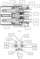
- a charging terminal for charging a target vehicle including: a charging gun 1 provided with a liquid inlet pipe 145 and a liquid return pipe 142 therein; a heat dissipation device 2 provided with an inlet and an outlet, where the inlet is connected to the liquid return pipe 142 via a pipeline; a fan 3 electrically connected to the heat dissipation device 2; a storage device 4 connected to the outlet of the heat dissipation device 2 via a pipeline and configured to store a cooling medium; a conveying device 6 connected to the storage device 4 via a pipeline and configured to convey the cooling medium in the storage device 4 to the liquid inlet pipe 145; at least five temperature sensors disposed at a DC+ terminal of the charging gun, a DC- terminal of the charging gun, a liquid outlet of the heat dissipation device, a liquid inlet of the heat dissipation device, and an air inlet of the fan,
- a maximum current of the charging terminal for charging the target vehicle is greater than 650 amperes.
- the heat dissipation device 2 may be a finned heat exchanger, a plate heat exchanger, a shell-and-tube heat exchanger, etc.
- the heat dissipation device 2 is an aluminum plate finned heat exchanger with a compact structure, a reduced weight, a small size and high heat transfer efficiency, and cooperates with the fan 3, resulting in an improved heat dissipation capacity.
- the conveying device 6 may be a pump or other devices capable of conveying a medium.
- the charging terminal further includes a cabinet, where the heat dissipation device 2, the fan 3, the storage device 4, the conveying device 6 and the control device are disposed inside the cabinet, and the charging gun 1 is disposed outside the cabinet.
- One or more of the heat dissipation device 2, the fan 3, the storage device 4, the conveying device 6 and the control device may also be disposed outside the cabinet, to achieve heat dissipation for a gun cable and a terminal cabinet system by means of liquid-liquid heat exchange.
- a valve 5 may be provided between the conveying device 6 and the storage device 4.
- the control device includes a master control board 7, and the charging terminal includes five temperature sensors, where the master control board 7 receives data from the five temperature sensors and controls the operations of the conveying device 6 and the fan 3 based on the data or the data and a current state of the charging terminal.
- the master control board 7 may be an SCT master control board that is electrically connected to each of the conveying device 6 and the fan 3.
- a direct current power supply 8 may supply power to each of the master control board 7, the fan 3, the conveying device 6, the temperature sensors, etc.
- the charging terminal further includes five temperature sensors (a temperature sensor 11 at a DC+ terminal of the charging gun, a temperature sensor 12 at a DC- terminal of the charging gun, a temperature sensor 22 at an oil inlet of the gun cable, a temperature sensor 21 at an oil outlet of the gun cable, and a temperature sensor 31 at the air inlet of the fan 3), which are disposed at the DC+ terminal of the charging gun, the DC- terminal of the charging gun, the liquid outlet of the heat dissipation device 2, the liquid inlet of the heat dissipation device 2, and the air inlet of the fan 3, respectively, and configured to measure a temperature T1 of the DC+ terminal of the charging gun, a temperature T2 of the DC- terminal of the charging gun, a temperature T3 of the oil inlet of the gun cable, a temperature T4 of the oil outlet of the gun cable, and a temperature T5 of the air inlet of the fan 3, respectively.
- five temperature sensors a temperature sensor 11 at a DC+ terminal of the charging gun, a temperature sensor 12 at
- the current operating state of the charging terminal includes starting charging, stopping charging, etc.
- the pump when the charging terminal starts charging, the pump is controlled to be turned on; and when the charging terminal stops charging and ⁇ T ⁇ 1°C, the pump is controlled to be turned off.
- a rotational speed of the pump may be divided into three levels in an ascending order, where a first level is 2000 rpm, i.e., 17% of a duty cycle; a second level is 2500 rpm, i.e., 22% of a duty cycle; and a third level is 3000 rpm, i.e., 27% of a duty cycle.
- a first level is 2000 rpm, i.e., 17% of a duty cycle
- a second level is 2500 rpm, i.e., 22% of a duty cycle
- a third level is 3000 rpm, i.e., 27% of a duty cycle.
- the operation of the fan 3 is controlled based on the temperature T1 of the DC+ terminal of the charging gun, the temperature T2 of the DC- terminal of the charging gun, the temperature T5 of the air inlet of the fan 3, ⁇ T, and the current state of the charging terminal.
- turning-on of the fan 3 is controlled based on the temperature T1 of the DC+ terminal of the charging gun, the temperature T2 of the DC- terminal of the charging gun, the temperature T5 of the air inlet of the fan 3 and the current state of the charging terminal. For example, when the charging terminal starts charging, a maximum value max (T1, T2) of T1 and T2 ⁇ 40°C and T5 ⁇ 20°C, the fan 3 is turned on.
- the speed of the fan 3 is adjusted based on the temperature T1 of the DC+ terminal of the charging gun and the temperature T2 of the DC- terminal of the charging gun.
- the rotational speed of the fan 3 is linearly adjusted based on max (T1, T2), that is, if the numerical value of max (T1, T2) becomes larger, the rotational speed of the fan 3 is adjusted to be higher; and if the numerical value of max (T1, T2) becomes smaller, the rotational speed of the fan 3 is adjusted to be lower.
- max (T1, T2) if the numerical value of max (T1, T2) becomes larger, the rotational speed of the fan 3 is adjusted to be higher; and if the numerical value of max (T1, T2) becomes smaller, the rotational speed of the fan 3 is adjusted to be lower.
- T1 ⁇ 50°C the fan 3 operates at a maximum rotational speed, that is, the fan 3 operates at the highest level.
- Turning-off of the fan 3 is controlled based on ⁇ T, the temperature T5 of the air inlet of the fan 3 and the current state of the charging terminal. For example, when the charging terminal stops charging, ⁇ T ⁇ 1°C, and T5 ⁇ 35°C, the fan 3 is turned off.
- the temperature sensors are arranged at five temperature acquisition points, and under the control of a logic algorithm of the SCT master control board 7, output rotational speeds of key liquid cooling components such as the fan 3 and a water pump are precisely set to achieve precise real-time dynamic adjustment of the liquid cooling heat dissipation system, resulting in an equilibrium between liquid cooling and noise.
- a liquid level sensor 41 is provided in the storage device 4 and configured to monitor the leakage of a cooling liquid in the pipeline; and a pressure sensor 9 is provided in the pipeline and configured to monitor whether an oil path high-pressure event occurs in the pipeline.
- the liquid level sensor 41, the pressure sensor 9 and the logic control of the SCT master control board 7 ensure the safety performance of the charging terminal in various scenarios of failure such as leakage of the cooling liquid, and blocking, overbending and damage of a cooling pipeline.
- the charging gun 1 includes a gun tip, a cable 14, and a gun tail, where the cable 14 is connected to each of the gun tip and the gun tail, and the gun tip and the gun tail are provided with a gun tip liquid-cooling module 13 and a gun tail liquid-cooling module, respectively.
- the cable 14 is provided with two liquid inlet pipes 145 and one liquid return pipe 142 ("two-inlet one-outlet" for short), where a DC+ wire 146 and a DC- wire 144 are immersed in and wrapped with the two liquid inlet pipes 145, respectively, end portions of the two liquid inlet pipes 145 converge at the gun tip and are in communication with the liquid return pipe 142, and the liquid return pipe 142 is independent of the two liquid inlet pipes 145.
- the liquid return pipe 142 is also in communication with the heat dissipation device 2 to introduce the warmed-up cooling medium to the heat dissipation device 2.
- the cable 14 further includes a cable sheath 141, a charging gun signal wire 143, the DC+ wire 146, the DC- wire 144, and a PE cable 18.
- the DC+ wire 146 and the DC- wire 144 may both be bare copper wires and are composed of multiple harnesses.
- the cable 14 may be provided with one liquid inlet pipe 145 and two liquid return pipes 142 ("one-inlet two-outlet" for short), where the DC+ wire 146 and the DC- wire 144 are immersed in and wrapped with the two liquid return pipes 142, respectively, an end portion of the liquid inlet pipe 145 is in communication with each of the two liquid return pipes 142 at the gun tip, and the liquid inlet pipe 145 is independent of the two liquid return pipes 142.
- the cooling medium in the one-inlet two-outlet pipe arrangement brings out more heat, so that the cable sheath 141 dissipates less heat.
- the one-inlet two-outlet pipe arrangement is more conducive to the heat dissipation from the charging gun 1, since a portion thereof likely coming into contact with a user has a lower temperature, resulting in improved user experience.
- the cable 14 maintained at a lower temperature is more conducive to long-lasting use of the gun cable, resulting in improved durability.
- the gun tip liquid-cooling module 13 is provided with a gun tip shell 131, two pins (a DC+ plug pin 132 and a DC- plug pin 133), an intermediate clamping plate 134, etc.
- a crimping area 50 is provided at each of end portions of the DC+ wire 146 and the DC- wire 144, and the two pins are used to be electrically connected to a target vehicle.
- the end portions of the two liquid inlet pipes 145 separately pass through the crimping areas 50, the two pins, and the intermediate clamping plate 134 and then converge into the liquid return pipe 142.
- Each liquid inlet pipe 145 carries away the heat generated by crimping resistance of the crimping areas 50 and part of the heat generated by the pins, to ensure that a temperature rise there is not excessively high.
- riveting, welding, screwing, etc. may be used for the crimping areas 50.
- the gun tail liquid-cooling module includes a DC+ gun tail liquid-cooling module 16 and a DC-gun tail liquid-cooling module 17, where the DC+ gun tail liquid-cooling module 16 is provided with a gun tail terminal 162, the end portion of the liquid inlet pipe 145, and an adapter 161.
- the gun tail terminal 162 may be a copper busbar terminal.
- One end of the end portion of the liquid inlet pipe 145 is connected to the conveying device 6, and the other end thereof passes through the gun tail terminal 162 and the adapter 161 and then is in communication with the liquid inlet pipe 145 of the cable 14 via the adapter 161.
- the gun tail terminal 162 is provided with a riveting portion 60.
- the cooling medium carries away heat from the riveting portion 60 of the gun tail terminal 162, and also carries away part of heat from the gun tail terminal 162 itself, to implement the heat dissipation from the gun tail, thereby ensuring that a temperature rise there is not excessively high. Furthermore, to avoid a potential risk of an excessively high temperature at the gun tail, an additional temperature sensor may be arranged in the cabinet to implement monitoring and thermal management in a potential high-temperature area. In addition to a riveting process, welding, screwing, etc. may be used for the crimping portion 60.
- the gun tail may also be provided with a signal wire plug-in terminal block 19, which may be a 16-pin terminal for outputting a variety of signals, and the PE cable 18 is grounded.
- a relationship for T1 to T5 conforms to the formula T1 ⁇ T2 ⁇ T4 ⁇ T3 ⁇ T5, where it may be said that T1 ⁇ T2 when a temperature difference between T1 and T2 ⁇ 5°C.
- the master control board 7 receives a temperature value measured by at least one temperature sensor that is in inconformity with the formula, it indicates that the temperature sensor is abnormal, and an abnormality alarm is given. For example, if T1 ⁇ T4, one of the temperature sensor at the DC+ terminal of the charging gun or the temperature sensor at the oil outlet of the gun cable necessarily fails due to damage.
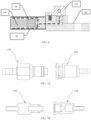
- the liquid inlet pipe 145 or the liquid return pipe 142 is connected, at the gun tail, to the pipeline inside the cabinet via a bidirectional cut-off-enabled plug assembly.
- the bidirectional cut-off-enabled plug assembly includes a male plug 151 and a female plug 152, where one end of each of the male plug 151 and the female plug 152 is socketed to the liquid inlet pipe 145 or the liquid return pipe 142 or the pipeline inside the cabinet, and the other ends thereof are plugged into each other.
- the male plug 151 and the female plug 152 When the male plug 151 and the female plug 152 are plugged into each other, the male plug 151 and the female plug 152 are in communication with each other for the cooling medium to pass through; and when the male plug 151 and the female plug 152 are released from each other, the male plug 151 and the female plug 152 are both cut off to prevent the cooling medium from flowing out.
- the liquid return pipe 142 is interfaced, via a terminal plug 15 (a male plug or a female plug) at the gun tail, with a terminal plug (a female plug or a male plug) provided on the pipeline inside the cabinet, to form the bidirectional cut-off-enabled plug assembly.
- the bidirectional cut-off-enabled plug assembly in replacement of a hoop commonly used in the industry, may implement fast pluggable fitting between a liquid cooling pipe of the charging gun 1 and a liquid cooling pipe inside the cabinet.
- a one-way stop valve may be used in combination with other measures to implement fast connection of the gun tail and the pipeline inside the cabinet.
- a performance test was performed on the charging terminal of an embodiment of the invention with a continuous charging current of 600 amperes and charging time of 30 min, where the test conditions were as follows: the cooling liquid being dimethyl silicone oil, the temperature T3 of the oil inlet of the gun cable in an initial state being 25°C, a liquid flow rate in the pipe being 4 L/min, and the pipes being in the one-inlet two-outlet arrangement.
- test results are shown in the following table, where thermal equilibrium is achieved 25 min after a peak of the temperature of the gun cable, a maximum temperature rise and a maximum temperature conform to the standard, temperatures at four points of the cable sheath (the four points obtained by evenly dividing the length of the gun cable) are all below 60°C, and a temperature rise of the gun cable terminal is below 50°C, that is, the charging performance test is in line with the national standard. That is, the charging terminal meets the requirement for a temperature rise during 600-ampere continuous charging.
Landscapes
- Engineering & Computer Science (AREA)
- Power Engineering (AREA)
- Transportation (AREA)
- Mechanical Engineering (AREA)
- Electric Propulsion And Braking For Vehicles (AREA)
Applications Claiming Priority (2)
| Application Number | Priority Date | Filing Date | Title |
|---|---|---|---|
| CN202210980073.6A CN115352295A (zh) | 2022-08-16 | 2022-08-16 | 充电终端 |
| PCT/CN2023/105212 WO2024037232A1 (zh) | 2022-08-16 | 2023-06-30 | 充电终端 |
Publications (2)
| Publication Number | Publication Date |
|---|---|
| EP4574542A1 true EP4574542A1 (de) | 2025-06-25 |
| EP4574542A4 EP4574542A4 (de) | 2025-12-03 |
Family
ID=84001644
Family Applications (1)
| Application Number | Title | Priority Date | Filing Date |
|---|---|---|---|
| EP23854137.9A Withdrawn EP4574542A4 (de) | 2022-08-16 | 2023-06-30 | Ladeterminal |
Country Status (3)
| Country | Link |
|---|---|
| EP (1) | EP4574542A4 (de) |
| CN (1) | CN115352295A (de) |
| WO (1) | WO2024037232A1 (de) |
Families Citing this family (10)
| Publication number | Priority date | Publication date | Assignee | Title |
|---|---|---|---|---|
| CN115352295A (zh) * | 2022-08-16 | 2022-11-18 | 武汉蔚来能源有限公司 | 充电终端 |
| CN115742805A (zh) * | 2022-11-29 | 2023-03-07 | 苏州一航电子科技股份有限公司 | 一种液冷充电枪 |
| CN116069083B (zh) * | 2023-01-12 | 2025-12-05 | 威睿电动汽车技术(宁波)有限公司 | 充电设备的温度控制方法、装置、设备及存储介质 |
| CN116315829A (zh) * | 2023-02-08 | 2023-06-23 | 深圳巴斯巴科技发展有限公司 | 一种液冷充电枪尾部液电隔离紧固连接装置 |
| CN116394785A (zh) * | 2023-03-29 | 2023-07-07 | 福建时代星云科技有限公司 | 一种具有风水冷组件的充电桩的冷却方法及系统 |
| CN118082562A (zh) * | 2024-03-30 | 2024-05-28 | 张家港友诚新能源科技股份有限公司 | 一种结构紧凑型液冷充电枪 |
| CN118596894B (zh) * | 2024-05-23 | 2025-03-18 | 江苏新源太阳能科技有限公司 | 用于光储充的自动配电装置 |
| DE102024125153B3 (de) * | 2024-09-03 | 2026-02-05 | Amphenol Tuchel Industrial GmbH | Flüssigkeitsgekühlter Ladestecker |
| CN120307917A (zh) * | 2025-05-26 | 2025-07-15 | 超聚变数字技术有限公司 | 液冷充电设备的控制方法及设备 |
| CN121043666A (zh) * | 2025-09-25 | 2025-12-02 | 上海福宁保远科技有限公司 | 一种通过液态合金均温扩展与液冷循环耦合的电缆枪头散热装置 |
Family Cites Families (32)
| Publication number | Priority date | Publication date | Assignee | Title |
|---|---|---|---|---|
| KR100471250B1 (ko) * | 2002-08-23 | 2005-03-10 | 현대자동차주식회사 | 전기 차량의 냉각 팬 제어장치 및 방법 |
| DE102010007975B4 (de) | 2010-02-15 | 2012-10-04 | Siemens Aktiengesellschaft | Ladestation für einen elektrischen Energiespeicher und zugehöriger elektrischer Energiespeicher |
| US9321362B2 (en) | 2014-02-05 | 2016-04-26 | Tesia Motors, Inc. | Cooling of charging cable |
| US9527403B2 (en) | 2014-04-29 | 2016-12-27 | Tesla Motors, Inc. | Charging station providing thermal conditioning of electric vehicle during charging session |
| US11052776B2 (en) | 2015-09-24 | 2021-07-06 | Ford Global Technologies, Llc | Charging station for electrified vehicles |
| US10913369B2 (en) | 2017-02-16 | 2021-02-09 | Ford Global Technologies, Llc | Charging energy recapture assembly and method |
| CN110014953B (zh) | 2017-09-30 | 2021-01-19 | 比亚迪股份有限公司 | 第一、第二充电连接件以及充电枪、车辆和充电系统 |
| CN110014955B (zh) | 2017-09-30 | 2021-01-19 | 比亚迪股份有限公司 | 第一、第二充电连接件以及充电枪、车辆和充电系统 |
| CN110014952A (zh) | 2017-09-30 | 2019-07-16 | 比亚迪股份有限公司 | 充电连接件、充电枪以及车辆和充电系统 |
| CN109599693B (zh) | 2017-09-30 | 2021-03-26 | 比亚迪股份有限公司 | 第一、第二充电连接件以及充电枪、车辆和充电系统 |
| CN207416579U (zh) | 2017-09-30 | 2018-05-29 | 比亚迪股份有限公司 | 充电装置以及车辆和充电桩 |
| CN110014947B (zh) * | 2017-09-30 | 2021-05-14 | 比亚迪股份有限公司 | 充电桩以及车辆 |
| CN109600961B (zh) | 2017-09-30 | 2020-11-20 | 比亚迪股份有限公司 | 充电连接件的散热器、充电装置、车辆和充电枪 |
| DE102017219736B4 (de) | 2017-11-07 | 2025-11-20 | Audi Ag | Ladesäule für ein Elektrofahrzeug |
| CN207790357U (zh) * | 2017-11-22 | 2018-08-31 | 青岛特来电新能源有限公司 | 充电终端和充电系统 |
| CN107878240A (zh) | 2017-11-22 | 2018-04-06 | 青岛特来电新能源有限公司 | 充电终端和充电系统 |
| US11084390B2 (en) | 2018-03-22 | 2021-08-10 | Tesla, Inc. | Liquid-cooled charging connector |
| CN108847316B (zh) * | 2018-06-06 | 2020-10-20 | 洛阳正奇机械有限公司 | 一种600a直流充电桩专用液冷电缆dc+和dc-的并冷冷却方式 |
| CN209845579U (zh) | 2018-10-31 | 2019-12-24 | 广州小鹏汽车科技有限公司 | 一种充电装置降温系统 |
| CN110239383A (zh) * | 2019-05-31 | 2019-09-17 | 南京康尼机电股份有限公司 | 新能源汽车大功率充电冷却系统及其监测方法 |
| CN112895959A (zh) * | 2019-12-04 | 2021-06-04 | 观致汽车有限公司 | 用于电动车辆的直流充电控制系统以及控制方法 |
| CN111016707B (zh) * | 2020-01-06 | 2024-04-12 | 四川永贵科技有限公司 | 一种电动汽车的液冷大电流充电系统及其控制方法 |
| CN213024106U (zh) * | 2020-09-17 | 2021-04-20 | 深圳市深国充充电设备有限公司 | 应用于专业充电站的中央液冷节能控制系统 |
| CN214164755U (zh) * | 2021-01-18 | 2021-09-10 | 江阴市中鼎节能流体科技有限公司 | 一种充电枪液冷系统 |
| CN215154005U (zh) * | 2021-05-28 | 2021-12-14 | 浙江富士精工科技有限公司 | 一种充电冷却装置 |
| CN113370814A (zh) * | 2021-07-28 | 2021-09-10 | 陕西绿能电子科技有限公司 | 一种液冷充电枪系统及基于其的充电控制方法 |
| CN113948742A (zh) * | 2021-08-31 | 2022-01-18 | 东风汽车集团股份有限公司 | 一种用于多燃电系统的散热装置以及车辆 |
| CN113799632B (zh) * | 2021-10-29 | 2023-03-10 | 广州锐速智能科技股份有限公司 | 冷却系统和大功率液冷超级快充设备 |
| CN216761472U (zh) * | 2021-12-17 | 2022-06-17 | 上海Abb联桩新能源技术有限公司 | 一种充电桩液冷系统 |
| CN114899639A (zh) * | 2022-04-29 | 2022-08-12 | 深圳市沃尔新能源电气科技股份有限公司 | 液冷式线缆连接器和充电枪 |
| CN115352295A (zh) * | 2022-08-16 | 2022-11-18 | 武汉蔚来能源有限公司 | 充电终端 |
| CN218640688U (zh) * | 2022-08-16 | 2023-03-17 | 武汉蔚来能源有限公司 | 一种用于向目标车辆充电的充电终端 |
-
2022
- 2022-08-16 CN CN202210980073.6A patent/CN115352295A/zh active Pending
-
2023
- 2023-06-30 EP EP23854137.9A patent/EP4574542A4/de not_active Withdrawn
- 2023-06-30 WO PCT/CN2023/105212 patent/WO2024037232A1/zh not_active Ceased
Also Published As
| Publication number | Publication date |
|---|---|
| EP4574542A4 (de) | 2025-12-03 |
| CN115352295A (zh) | 2022-11-18 |
| WO2024037232A1 (zh) | 2024-02-22 |
Similar Documents
| Publication | Publication Date | Title |
|---|---|---|
| WO2024037232A1 (zh) | 充电终端 | |
| CN207338673U (zh) | 车辆的充电连接件以及车辆 | |
| CN204732499U (zh) | 一种用于电动汽车的可扩展式液冷电池模组 | |
| CN107425318B (zh) | 充电枪 | |
| CN109728459B (zh) | 电液集成式连接装置和车辆 | |
| CN106299536A (zh) | 一种用于电动汽车的可扩展式液冷电池模组 | |
| CN219498255U (zh) | 一种液冷连接器 | |
| CN116315905A (zh) | 充电枪及充电设备 | |
| CN218640688U (zh) | 一种用于向目标车辆充电的充电终端 | |
| CN113765188A (zh) | 电站、充电系统、液冷系统及其控制方法和控制装置 | |
| CN217705516U (zh) | 一种大功率充电枪散热装置 | |
| CN115939819A (zh) | 一种充电枪液体冷却结构 | |
| CN108232361A (zh) | 一种动力电池包的散热系统以及动力电池的散热系统 | |
| CN216783279U (zh) | 一种大功率充电接口的冷却结构 | |
| CN222645823U (zh) | 充电枪和充电系统 | |
| WO2025232487A1 (zh) | 动力电池和电动车辆 | |
| CN220753092U (zh) | 一种增加柔性的css母排 | |
| CN208315709U (zh) | 兼顾风冷和液冷的动力电池冷却板 | |
| CN217347523U (zh) | 分体式充电系统 | |
| CN114937882A (zh) | 一种液冷充电枪端子包胶密封结构 | |
| CN223224207U (zh) | 一种高效散热的直流液冷充电座 | |
| CN221746951U (zh) | 一种应用于大电流或脉冲电流的空心水冷线圈装置 | |
| CN219759910U (zh) | 一种断路单元及电池 | |
| CN222108406U (zh) | 液冷散热系统和充电终端设备 | |
| CN223877879U (zh) | 一种线缆、充电枪和充电装置 |
Legal Events
| Date | Code | Title | Description |
|---|---|---|---|
| STAA | Information on the status of an ep patent application or granted ep patent |
Free format text: STATUS: THE INTERNATIONAL PUBLICATION HAS BEEN MADE |
|
| PUAI | Public reference made under article 153(3) epc to a published international application that has entered the european phase |
Free format text: ORIGINAL CODE: 0009012 |
|
| STAA | Information on the status of an ep patent application or granted ep patent |
Free format text: STATUS: REQUEST FOR EXAMINATION WAS MADE |
|
| 17P | Request for examination filed |
Effective date: 20250127 |
|
| AK | Designated contracting states |
Kind code of ref document: A1 Designated state(s): AL AT BE BG CH CY CZ DE DK EE ES FI FR GB GR HR HU IE IS IT LI LT LU LV MC ME MK MT NL NO PL PT RO RS SE SI SK SM TR |
|
| STAA | Information on the status of an ep patent application or granted ep patent |
Free format text: STATUS: EXAMINATION IS IN PROGRESS |
|
| DAV | Request for validation of the european patent (deleted) | ||
| DAX | Request for extension of the european patent (deleted) | ||
| A4 | Supplementary search report drawn up and despatched |
Effective date: 20251031 |
|
| RIC1 | Information provided on ipc code assigned before grant |
Ipc: B60L 53/16 20190101AFI20251027BHEP Ipc: B60L 53/302 20190101ALI20251027BHEP Ipc: B60L 53/10 20190101ALI20251027BHEP Ipc: H01R 13/00 20060101ALI20251027BHEP Ipc: B60L 53/18 20190101ALI20251027BHEP |
|
| 17Q | First examination report despatched |
Effective date: 20251112 |
|
| STAA | Information on the status of an ep patent application or granted ep patent |
Free format text: STATUS: THE APPLICATION HAS BEEN WITHDRAWN |
|
| 18W | Application withdrawn |
Effective date: 20260219 |