EP4574573A1 - Aussenrückblickspiegel für kraftfahrzeuge - Google Patents
Aussenrückblickspiegel für kraftfahrzeuge Download PDFInfo
- Publication number
- EP4574573A1 EP4574573A1 EP24383177.3A EP24383177A EP4574573A1 EP 4574573 A1 EP4574573 A1 EP 4574573A1 EP 24383177 A EP24383177 A EP 24383177A EP 4574573 A1 EP4574573 A1 EP 4574573A1
- Authority
- EP
- European Patent Office
- Prior art keywords
- actuator
- backplate
- movable part
- assembly
- cover frame
- Prior art date
- Legal status (The legal status is an assumption and is not a legal conclusion. Google has not performed a legal analysis and makes no representation as to the accuracy of the status listed.)
- Pending
Links
Images






Classifications
-
- B—PERFORMING OPERATIONS; TRANSPORTING
- B60—VEHICLES IN GENERAL
- B60R—VEHICLES, VEHICLE FITTINGS, OR VEHICLE PARTS, NOT OTHERWISE PROVIDED FOR
- B60R1/00—Optical viewing arrangements; Real-time viewing arrangements for drivers or passengers using optical image capturing systems, e.g. cameras or video systems specially adapted for use in or on vehicles
- B60R1/02—Rear-view mirror arrangements
- B60R1/06—Rear-view mirror arrangements mounted on vehicle exterior
- B60R1/062—Rear-view mirror arrangements mounted on vehicle exterior with remote control for adjusting position
- B60R1/07—Rear-view mirror arrangements mounted on vehicle exterior with remote control for adjusting position by electrically powered actuators
- B60R1/072—Rear-view mirror arrangements mounted on vehicle exterior with remote control for adjusting position by electrically powered actuators for adjusting the mirror relative to its housing
Definitions
- the invention belongs to the technical field of manufacturing of exterior rear-view mirrors for vehicles.
- Some exterior rear-view mirror assemblies for motor vehicles include a mirror base or foot adapted for its attachment to vehicle's bodywork, and a mirror head arranged on the mirror foot as well as a mirror glass accommodated in the mirror head and arranged rigidly thereto. At least one articulation is provided between the mirror head and the arrangement of the mirror foot on the vehicle.
- An exterior rear-view mirror assembly may include a mirror actuator operable to adjust a mirror reflective element relative to the mirror casing, so as to adjust a rearward field of view of the driver of the vehicle.
- Foldable exterior mirror assemblies include an actuator that pivots or folds the mirror casing relative to the side of the vehicle.
- An aspect of the invention refers to an exterior rear view mirror assembly for vehicles, wherein the assembly comprises: a support base for attaching the assembly to a vehicle, and a mirror head coupled to the support base.
- the mirror head comprises: a housing comprising a cover frame, a backplate having an outer side and an inner side, and a mirror surface supported on the outer side of the backplate, and an actuator formed by a base and a movable part coupled to the base and movable with respect to the base.
- the cover frame may be integrally formed with the housing or it may be attached to the housing.
- the backplate is coupled to the movable part of the actuator, such that the backplate is movable by means of the actuator, and the cover frame is also coupled to the movable part of the actuator.
- the backplate and the movable part of the actuator are directly coupled, that is, these two components back plate and movable part of the actuator, are attached to each other without participation of any other component acting as interface between the back plate and movable part of the actuator, although fastening means, such as screws or similar means, may be used for the attachment.
- the cover frame and the movable part of the actuator are directly coupled, that is, these two components back plate and movable part of the actuator, are attached to each other without participation of any other component acting as interface between the back plate and movable part of the actuator, although fastening means, such as screws or similar means, may be used for the attachment.
- the cover frame has a window and the movable part of the actuator or at least a part of it, it is placed in the window of the cover frame.
- the backplate has first engaging means at its inner side, and the first engaging means pass through the window of the cover frame and are engaged with the movable part of the actuator.
- the first engaging means are flexible clips protruding from the inner side of the backplate. These flexible clips have one end integrally formed with the inner side of the backplate, and a free end configured as a hook.
- the movable part of the actuator has a first contacting surface and a second contacting surface, distanced from the first contacting surface.
- the first contacting surface of the actuator is closer to the mirror surface than the second contacting surface, and first engaging means of the backplate are engaged with the second contacting surface.
- the assembly includes second engaging means for coupling the movable part of the actuator with the cover frame, and wherein part of these second engaging means are formed at the cover frame's window, and part of these second engaging means are formed in the movable part of the actuator.
- the assembly may comprise biasing means interposed in between the inner side of the backplate and a front surface of the movable part of the actuator, wherein these biasing means are configured to press on the movable part of the actuator away from the backplate.
- the biassing means are embodied as flexible tabs having one end integrally formed with the inner side of the backplate and another end is a free end.
- the biassing means are in contact with the first contacting surface of the actuator, or with any other front surface of the movable of the actuator. Therefore, the fixation takes place between these biasing means contacting the front surface of the actuator and the fastening of the clips with the second contacting surface.
- the second engaging means comprises tongues extending radially from the movable part of the actuator, and fixation clips integrally formed at the casing frame's window.
- the casing frame's window has an annular surface extending radially, and the movable part of the actuator is retained in between the fixation clips and the annular surface of the window.
- the fixation clips are in contact with the first contacting surface of the movable part, and the tongues are in contact with the annular surface of the window.
- the backplate with the mirror surface is interchangeable as it is independent of the cover frame, so that, the backplate can be disassembled without removing the cover frame. This results in a much more robust assembly with far fewer problems with tolerances and backplate disengagement without the need to remove the frame.
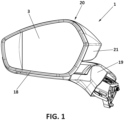
- the exterior rear-view mirror assembly (1) comprises: a support base (19) for attaching the assembly (1) to a vehicle, a mirror head (20) coupled to the support base (19), and a mirror surface (3).
- the mirror head (20) comprises a housing (21), a cover frame (7), and a backplate (2) having an outer side (2a) and an inner side (2b), and with the mirror surface (3) placed on the outer side (2a).
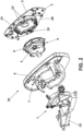
- An actuator (4) which is formed by a base (5) and a movable part (6) which is movable with respect to the base (5), is enclosed in the mirror head (20).
- the base (5) of the actuator (4) is attached to a housing bracket (25) which in turn is coupled to the support base (19) (shown in Figure 15 ), and the backplate (2) is coupled or attached directly to the movable part (6) of the actuator (4), such that the backplate (2) is movable by means of the actuator (4).
- the cover frame (7) is also coupled or attached directly to the movable part (6) of the actuator (4).
- the backplate (2) with the mirror surface (3) and the cover frame (7) move in tandem, with the advantage that the backplate (2) is independent from the cover frame (7) so that it can be dissembled easily without removing the cover frame (7).
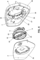
- the backplate (2) has a frame (14) formed on its inner side (2b), and first engaging means, which in this embodiment are realized as flexible clips (10), protruding from the frame (14).
- the backplate (2) is a flat or slightly curved body, and the frame (14) is formed on the inner side (2b) of the backplate (2).
- the flexible clips (10) have one end integrally formed with the frame (14) of the backplate (2), and a free end (1 0a) configured as a hook which protrudes internally in the assembly.
- the frame (14) is a wall extending axially from the surface of the backplate (2), in particular projecting from its inner side (2b) and configured as a closed and continuous loop.
- the backplate (2) has flexible tabs (11) having one end also integrally formed with the frame (14) and the other end is a free end.
- the flexible tabs (11) project from the frame (14) and are inclined towards the center of the frame (14).
- the flexible tabs (11) are inclined towards the outer side of the assembly.
- the movable part (6) of the actuator (4) has a first contacting surface (12) and a second contacting surface (13) distanced from the first contacting surface (12), wherein the first contacting surface (12) of the actuator (4) is closer to the mirror surface (3) than the second contacting surface (13).
- the flexible clips (10) of the backplate (2) are configured to be engaged with the second contacting surface (13) of the movable part (6), as shown more clearly in the enlarged detail "D" of Figure 6 , so as to press the movable part (6) towards the backplate (2).
- the backplate (2) and the movable part (6) of the actuator (4) are directly attached, without participation of any other component.
- the flexible tabs (11) are interposed in between the inner side (2b) of the backplate (2) and the first contacting surface (12) of the movable part (6) of the actuator (4). These flexible tabs (11) act as biasing means for pressing the movable part (6) of the888 actuator (6) away from the backplate (2), that is, in an opposite direction to the outer side, and they can be in contact with any front surface of the movable part (6) for example with the first contacting surface (12).
- the assembly (1) has second engaging means for coupling the movable part (6) of the actuator (4) with the cover frame (7).
- These second engaging means comprises tongues (15) extending radially from the movable part (6) of the actuator (4), and fixation clips (16) integrally formed with the cover frame (7).
- the tongues (15) extend radially from the movable part (6) in between the first and second contacting surfaces (12, 13).
- the cover frame (7) has a window (9) and an internal wall (22) surrounding the window (9), and the movable part (6) of the actuator (4) or at least a part of it, is received in that window (9), and the fixation clips (16) are integrally formed with the internal wall (22) of the cover frame (7).
- the fixation clips (16) project from the cover frame (7) towards the exterior surface of the cover frame (7).
- the fixation clips (16) may be inclined towards the window (9).
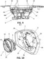
- the frame (14) of the backplate (2) in this embodiment is circumferential and concentric with the internal wall (22), and it is received at least in part in the internal wall (22). Furthermore, the internal wall (22) of the cover frame (7) has an annular surface (17) extending radially, and the movable part (6) of the actuator (4) is retained in between the fixation clips (16) and the annular surface (17) of the internal wall (22).
- the annular surface (17) has some notches (23) for the passage of the flexible clips (10) for their fixation to the movable part (6) of the actuator (4).
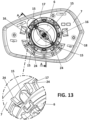
- fixation clips (16) are in contact with the first contacting surface (12) of the movable part (6) as better shown in the enlarged detail "A" of Figure 11 , and in Figure 14 , so that the fixation clips (16) retain the movable part (6), and the tongues (15) are in contact with the annular surface (17) of the internal wall (22), in particular the tongues (15) are received inside walls (24) for the correct positioning of the tongues (15).
- the cover frame (7) and the movable part (6) of the actuator (4) are directly coupled to each other.
- the cover frame (7) has an outer wall (18) extending along the perimeter of the cover frame (7), and this outer wall (18) at least partially surrounds the backplate (2).
- Another aspect of the invention refers to a method of assembling the exterior rear view mirror assembly previously defined, wherein the method comprises the following steps:
- the method also includes a step of forming or attaching a mirror surface (3) on the outer side (2a) of the backplate (2).
- the direct coupling between the backplate (2) and the movable part (6) of the actuator (4), and the direct coupling between the cover frame (7) to the movable part (6) of the actuator (4), mean that those components are attached without participation of any other component acting as interface between them, although fastening means, such as screws or similar means, may be used for the attachment.
Landscapes
- Engineering & Computer Science (AREA)
- Multimedia (AREA)
- Mechanical Engineering (AREA)
- Rear-View Mirror Devices That Are Mounted On The Exterior Of The Vehicle (AREA)
Priority Applications (3)
| Application Number | Priority Date | Filing Date | Title |
|---|---|---|---|
| EP24383177.3A EP4574573A1 (de) | 2024-10-25 | 2024-10-25 | Aussenrückblickspiegel für kraftfahrzeuge |
| US19/364,428 US20260116296A1 (en) | 2024-10-25 | 2025-10-21 | Exterior rear view mirror assembly for vehicles |
| CN202511531147.8A CN121929060A (zh) | 2024-10-25 | 2025-10-24 | 车辆用的外后视镜组件 |
Applications Claiming Priority (1)
| Application Number | Priority Date | Filing Date | Title |
|---|---|---|---|
| EP24383177.3A EP4574573A1 (de) | 2024-10-25 | 2024-10-25 | Aussenrückblickspiegel für kraftfahrzeuge |
Publications (1)
| Publication Number | Publication Date |
|---|---|
| EP4574573A1 true EP4574573A1 (de) | 2025-06-25 |
Family
ID=93376072
Family Applications (1)
| Application Number | Title | Priority Date | Filing Date |
|---|---|---|---|
| EP24383177.3A Pending EP4574573A1 (de) | 2024-10-25 | 2024-10-25 | Aussenrückblickspiegel für kraftfahrzeuge |
Country Status (3)
| Country | Link |
|---|---|
| US (1) | US20260116296A1 (de) |
| EP (1) | EP4574573A1 (de) |
| CN (1) | CN121929060A (de) |
Citations (3)
| Publication number | Priority date | Publication date | Assignee | Title |
|---|---|---|---|---|
| EP0433584B1 (de) * | 1989-12-15 | 1993-05-19 | Hohe Kg | Aussenspiegel für ein Kraftfahrzeug mit aufsteckbarer Kappe |
| US20130067719A1 (en) * | 2011-09-20 | 2013-03-21 | Murakami Corporation | Door mirror |
| US20190375331A1 (en) * | 2016-09-20 | 2019-12-12 | Kabushiki Kaisha Honda Lock | Door mirror apparatus for vehicle |
-
2024
- 2024-10-25 EP EP24383177.3A patent/EP4574573A1/de active Pending
-
2025
- 2025-10-21 US US19/364,428 patent/US20260116296A1/en active Pending
- 2025-10-24 CN CN202511531147.8A patent/CN121929060A/zh active Pending
Patent Citations (3)
| Publication number | Priority date | Publication date | Assignee | Title |
|---|---|---|---|---|
| EP0433584B1 (de) * | 1989-12-15 | 1993-05-19 | Hohe Kg | Aussenspiegel für ein Kraftfahrzeug mit aufsteckbarer Kappe |
| US20130067719A1 (en) * | 2011-09-20 | 2013-03-21 | Murakami Corporation | Door mirror |
| US20190375331A1 (en) * | 2016-09-20 | 2019-12-12 | Kabushiki Kaisha Honda Lock | Door mirror apparatus for vehicle |
Also Published As
| Publication number | Publication date |
|---|---|
| CN121929060A (zh) | 2026-04-28 |
| US20260116296A1 (en) | 2026-04-30 |
Similar Documents
| Publication | Publication Date | Title |
|---|---|---|
| JP4432598B2 (ja) | ドライバ側エアバッグをステアリングホイールに連結する方法と装置 | |
| EP2253510B1 (de) | Modularer Rückspiegel und Montageverfahren dafür | |
| EP0737138B1 (de) | Drehverbindung für einen seitlichen aussenrückblickspiegel | |
| US11110863B2 (en) | Connector arrangement for a motor vehicle rear-view mirror | |
| JP2005075337A (ja) | 自動車用ヘッドランプとフェンダ間の間隙保持構造 | |
| JP2023524260A (ja) | アクチュエータを備えた後方視界装置、およびそれを備えた車両 | |
| US7448589B2 (en) | Rear view mirror with snap connection | |
| US20260116296A1 (en) | Exterior rear view mirror assembly for vehicles | |
| US11859684B2 (en) | Rubber elastic bearing for a drive unit in a motor vehicle | |
| EP1138552A2 (de) | Fahrzeug- Rückblickspiegelanordnung | |
| EP4392289B1 (de) | Montageelement für rückspiegelanordnung | |
| EP4253149B1 (de) | Logo-lampenvorrichtung, rückblicksystem, fahrzeug und montageverfahren | |
| CN115139906B (zh) | 用于道路车辆的外置后视镜组件、及其系统和制造方法 | |
| JP2026077613A (ja) | 車両用外部リアビューミラーアセンブリ | |
| CN114945754B (zh) | 具有接纳机构和球铰链的接合组件 | |
| CN100362385C (zh) | 透镜驱动装置 | |
| JP4406856B2 (ja) | ヘッドランプの取付構造 | |
| US8075146B2 (en) | Fixing device for position regulating mechanisms for external rear-view mirrors on motor vehicles | |
| CN116157604B (zh) | 用于车辆的盖紧固系统 | |
| CN114619960B (zh) | 汽车 | |
| US20240416845A1 (en) | Mounting systems for securing components to vehicle body panels | |
| EP3597486B1 (de) | Aussenspiegel mit reduziertem klappgeräusch | |
| JP4149721B2 (ja) | 車両用熱交換器の取付構造 | |
| CN111483397A (zh) | 外后视镜 | |
| CN114728616B (zh) | 紧固结构、机动车辆的外部视觉单元以及用于组装或拆卸紧固结构的方法 |
Legal Events
| Date | Code | Title | Description |
|---|---|---|---|
| PUAI | Public reference made under article 153(3) epc to a published international application that has entered the european phase |
Free format text: ORIGINAL CODE: 0009012 |
|
| STAA | Information on the status of an ep patent application or granted ep patent |
Free format text: STATUS: THE APPLICATION HAS BEEN PUBLISHED |
|
| AK | Designated contracting states |
Kind code of ref document: A1 Designated state(s): AL AT BE BG CH CY CZ DE DK EE ES FI FR GB GR HR HU IE IS IT LI LT LU LV MC ME MK MT NL NO PL PT RO RS SE SI SK SM TR |
|
| STAA | Information on the status of an ep patent application or granted ep patent |
Free format text: STATUS: REQUEST FOR EXAMINATION WAS MADE |
|
| 17P | Request for examination filed |
Effective date: 20251222 |