EP4574595A1 - Bremse reibungskoeffizient (ì) schätzung für prognose und health monitoring management (phm) und verbesserte lastbalance (lb) - Google Patents
Bremse reibungskoeffizient (ì) schätzung für prognose und health monitoring management (phm) und verbesserte lastbalance (lb) Download PDFInfo
- Publication number
- EP4574595A1 EP4574595A1 EP24216295.6A EP24216295A EP4574595A1 EP 4574595 A1 EP4574595 A1 EP 4574595A1 EP 24216295 A EP24216295 A EP 24216295A EP 4574595 A1 EP4574595 A1 EP 4574595A1
- Authority
- EP
- European Patent Office
- Prior art keywords
- wheel
- brake
- deceleration
- assemblies
- force
- Prior art date
- Legal status (The legal status is an assumption and is not a legal conclusion. Google has not performed a legal analysis and makes no representation as to the accuracy of the status listed.)
- Pending
Links
Images


Classifications
-
- B—PERFORMING OPERATIONS; TRANSPORTING
- B60—VEHICLES IN GENERAL
- B60T—VEHICLE BRAKE CONTROL SYSTEMS OR PARTS THEREOF; BRAKE CONTROL SYSTEMS OR PARTS THEREOF, IN GENERAL; ARRANGEMENT OF BRAKING ELEMENTS ON VEHICLES IN GENERAL; PORTABLE DEVICES FOR PREVENTING UNWANTED MOVEMENT OF VEHICLES; VEHICLE MODIFICATIONS TO FACILITATE COOLING OF BRAKES
- B60T8/00—Arrangements for adjusting wheel-braking force to meet varying vehicular or ground-surface conditions, e.g. limiting or varying distribution of braking force
- B60T8/32—Arrangements for adjusting wheel-braking force to meet varying vehicular or ground-surface conditions, e.g. limiting or varying distribution of braking force responsive to a speed condition, e.g. acceleration or deceleration
- B60T8/72—Arrangements for adjusting wheel-braking force to meet varying vehicular or ground-surface conditions, e.g. limiting or varying distribution of braking force responsive to a speed condition, e.g. acceleration or deceleration responsive to a difference between a speed condition, e.g. deceleration, and a fixed reference
- B60T8/74—Arrangements for adjusting wheel-braking force to meet varying vehicular or ground-surface conditions, e.g. limiting or varying distribution of braking force responsive to a speed condition, e.g. acceleration or deceleration responsive to a difference between a speed condition, e.g. deceleration, and a fixed reference sensing a rate of change of velocity
-
- B—PERFORMING OPERATIONS; TRANSPORTING
- B60—VEHICLES IN GENERAL
- B60T—VEHICLE BRAKE CONTROL SYSTEMS OR PARTS THEREOF; BRAKE CONTROL SYSTEMS OR PARTS THEREOF, IN GENERAL; ARRANGEMENT OF BRAKING ELEMENTS ON VEHICLES IN GENERAL; PORTABLE DEVICES FOR PREVENTING UNWANTED MOVEMENT OF VEHICLES; VEHICLE MODIFICATIONS TO FACILITATE COOLING OF BRAKES
- B60T13/00—Transmitting braking action from initiating means to ultimate brake actuator with power assistance or drive; Brake systems incorporating such transmitting means, e.g. air-pressure brake systems
- B60T13/10—Transmitting braking action from initiating means to ultimate brake actuator with power assistance or drive; Brake systems incorporating such transmitting means, e.g. air-pressure brake systems with fluid assistance, drive, or release
- B60T13/66—Electrical control in fluid-pressure brake systems
- B60T13/662—Electrical control in fluid-pressure brake systems characterised by specified functions of the control system components
-
- B—PERFORMING OPERATIONS; TRANSPORTING
- B60—VEHICLES IN GENERAL
- B60T—VEHICLE BRAKE CONTROL SYSTEMS OR PARTS THEREOF; BRAKE CONTROL SYSTEMS OR PARTS THEREOF, IN GENERAL; ARRANGEMENT OF BRAKING ELEMENTS ON VEHICLES IN GENERAL; PORTABLE DEVICES FOR PREVENTING UNWANTED MOVEMENT OF VEHICLES; VEHICLE MODIFICATIONS TO FACILITATE COOLING OF BRAKES
- B60T17/00—Component parts, details, or accessories of power brake systems not covered by groups B60T8/00, B60T13/00 or B60T15/00, or presenting other characteristic features
- B60T17/18—Safety devices; Monitoring
- B60T17/22—Devices for monitoring or checking brake systems; Signal devices
-
- B—PERFORMING OPERATIONS; TRANSPORTING
- B60—VEHICLES IN GENERAL
- B60T—VEHICLE BRAKE CONTROL SYSTEMS OR PARTS THEREOF; BRAKE CONTROL SYSTEMS OR PARTS THEREOF, IN GENERAL; ARRANGEMENT OF BRAKING ELEMENTS ON VEHICLES IN GENERAL; PORTABLE DEVICES FOR PREVENTING UNWANTED MOVEMENT OF VEHICLES; VEHICLE MODIFICATIONS TO FACILITATE COOLING OF BRAKES
- B60T17/00—Component parts, details, or accessories of power brake systems not covered by groups B60T8/00, B60T13/00 or B60T15/00, or presenting other characteristic features
- B60T17/18—Safety devices; Monitoring
- B60T17/22—Devices for monitoring or checking brake systems; Signal devices
- B60T17/221—Procedure or apparatus for checking or keeping in a correct functioning condition of brake systems
-
- B—PERFORMING OPERATIONS; TRANSPORTING
- B60—VEHICLES IN GENERAL
- B60T—VEHICLE BRAKE CONTROL SYSTEMS OR PARTS THEREOF; BRAKE CONTROL SYSTEMS OR PARTS THEREOF, IN GENERAL; ARRANGEMENT OF BRAKING ELEMENTS ON VEHICLES IN GENERAL; PORTABLE DEVICES FOR PREVENTING UNWANTED MOVEMENT OF VEHICLES; VEHICLE MODIFICATIONS TO FACILITATE COOLING OF BRAKES
- B60T8/00—Arrangements for adjusting wheel-braking force to meet varying vehicular or ground-surface conditions, e.g. limiting or varying distribution of braking force
- B60T8/17—Using electrical or electronic regulation means to control braking
- B60T8/1701—Braking or traction control means specially adapted for particular types of vehicles
- B60T8/1703—Braking or traction control means specially adapted for particular types of vehicles for aircrafts
-
- B—PERFORMING OPERATIONS; TRANSPORTING
- B60—VEHICLES IN GENERAL
- B60T—VEHICLE BRAKE CONTROL SYSTEMS OR PARTS THEREOF; BRAKE CONTROL SYSTEMS OR PARTS THEREOF, IN GENERAL; ARRANGEMENT OF BRAKING ELEMENTS ON VEHICLES IN GENERAL; PORTABLE DEVICES FOR PREVENTING UNWANTED MOVEMENT OF VEHICLES; VEHICLE MODIFICATIONS TO FACILITATE COOLING OF BRAKES
- B60T8/00—Arrangements for adjusting wheel-braking force to meet varying vehicular or ground-surface conditions, e.g. limiting or varying distribution of braking force
- B60T8/17—Using electrical or electronic regulation means to control braking
- B60T8/171—Detecting parameters used in the regulation; Measuring values used in the regulation
-
- B—PERFORMING OPERATIONS; TRANSPORTING
- B60—VEHICLES IN GENERAL
- B60T—VEHICLE BRAKE CONTROL SYSTEMS OR PARTS THEREOF; BRAKE CONTROL SYSTEMS OR PARTS THEREOF, IN GENERAL; ARRANGEMENT OF BRAKING ELEMENTS ON VEHICLES IN GENERAL; PORTABLE DEVICES FOR PREVENTING UNWANTED MOVEMENT OF VEHICLES; VEHICLE MODIFICATIONS TO FACILITATE COOLING OF BRAKES
- B60T8/00—Arrangements for adjusting wheel-braking force to meet varying vehicular or ground-surface conditions, e.g. limiting or varying distribution of braking force
- B60T8/17—Using electrical or electronic regulation means to control braking
- B60T8/172—Determining control parameters used in the regulation, e.g. by calculations involving measured or detected parameters
-
- B—PERFORMING OPERATIONS; TRANSPORTING
- B60—VEHICLES IN GENERAL
- B60T—VEHICLE BRAKE CONTROL SYSTEMS OR PARTS THEREOF; BRAKE CONTROL SYSTEMS OR PARTS THEREOF, IN GENERAL; ARRANGEMENT OF BRAKING ELEMENTS ON VEHICLES IN GENERAL; PORTABLE DEVICES FOR PREVENTING UNWANTED MOVEMENT OF VEHICLES; VEHICLE MODIFICATIONS TO FACILITATE COOLING OF BRAKES
- B60T8/00—Arrangements for adjusting wheel-braking force to meet varying vehicular or ground-surface conditions, e.g. limiting or varying distribution of braking force
- B60T8/32—Arrangements for adjusting wheel-braking force to meet varying vehicular or ground-surface conditions, e.g. limiting or varying distribution of braking force responsive to a speed condition, e.g. acceleration or deceleration
- B60T8/58—Arrangements for adjusting wheel-braking force to meet varying vehicular or ground-surface conditions, e.g. limiting or varying distribution of braking force responsive to a speed condition, e.g. acceleration or deceleration responsive to speed and another condition or to plural speed conditions
-
- B—PERFORMING OPERATIONS; TRANSPORTING
- B64—AIRCRAFT; AVIATION; COSMONAUTICS
- B64C—AEROPLANES; HELICOPTERS
- B64C25/00—Alighting gear
- B64C25/32—Alighting gear characterised by elements which contact the ground or similar surface
- B64C25/42—Arrangement or adaptation of brakes
-
- B—PERFORMING OPERATIONS; TRANSPORTING
- B64—AIRCRAFT; AVIATION; COSMONAUTICS
- B64F—GROUND OR AIRCRAFT-CARRIER-DECK INSTALLATIONS SPECIALLY ADAPTED FOR USE IN CONNECTION WITH AIRCRAFT; DESIGNING, MANUFACTURING, ASSEMBLING, CLEANING, MAINTAINING OR REPAIRING AIRCRAFT, NOT OTHERWISE PROVIDED FOR; HANDLING, TRANSPORTING, TESTING OR INSPECTING AIRCRAFT COMPONENTS, NOT OTHERWISE PROVIDED FOR
- B64F5/00—Designing, manufacturing, assembling, cleaning, maintaining or repairing aircraft, not otherwise provided for; Handling, transporting, testing or inspecting aircraft components, not otherwise provided for
- B64F5/60—Testing or inspecting aircraft components or systems
-
- B—PERFORMING OPERATIONS; TRANSPORTING
- B60—VEHICLES IN GENERAL
- B60T—VEHICLE BRAKE CONTROL SYSTEMS OR PARTS THEREOF; BRAKE CONTROL SYSTEMS OR PARTS THEREOF, IN GENERAL; ARRANGEMENT OF BRAKING ELEMENTS ON VEHICLES IN GENERAL; PORTABLE DEVICES FOR PREVENTING UNWANTED MOVEMENT OF VEHICLES; VEHICLE MODIFICATIONS TO FACILITATE COOLING OF BRAKES
- B60T2240/00—Monitoring, detecting wheel/tyre behaviour; counteracting thereof
Definitions
- a method for controlling brake assemblies of a vehicle includes receiving a deceleration of each wheel assembly of a plurality of wheel assemblies of the vehicle, comparing the deceleration of each wheel assembly to an average deceleration of the plurality of wheel assemblies, and, responsive to one or more of the deceleration of each wheel assembly of one or more wheel assemblies being outside a predetermined range of the average deceleration of the plurality of wheel assemblies, reporting a warning message to a maintenance crew to inspect one or more brake assemblies associated with the one or more wheel assemblies.
- the braking system includes a brake control unit.
- the brake control unit is configured to receive a deceleration of each wheel assembly of a plurality of wheel assemblies of the vehicle, compare the deceleration of each wheel assembly to an average deceleration of the plurality of wheel assemblies, and, responsive to one or more of the deceleration of each wheel assembly of one or more wheel assemblies being outside a predetermined range of the average deceleration of the plurality of wheel assemblies, report a warning message to a maintenance crew to inspect one or more brake assemblies associated with the one or more wheel assemblies.
- the brake control unit is further configured to, responsive to one or more of the deceleration of each wheel assembly of one or more wheel assemblies being within the predetermined range of the average deceleration of the plurality of wheel assemblies, identify that all brakes are functioning in a similar manner and reporting no issues.
- the brake control unit is further configured to define a wheel deceleration to brake force ratio based on brake information obtained from development and qualification of a plurality of brake assemblies of the plurality of wheel assemblies of the vehicle, during taxi when a force is applied to brake pedals, calculate a ratio of deceleration to brake force for each wheel assembly of the plurality of wheel assemblies, determine whether the ratio of deceleration to brake force for each wheel assembly of the plurality of wheel assemblies as compared to the defined wheel deceleration to brake force ratio within a predetermined range, and, responsive to one or more ratios of deceleration to brake force for one or more wheel assembly of the plurality of wheel assemblies as compared to the defined wheel deceleration to brake force ratio being outside the predetermined range, report the warning message to the maintenance crew to inspect the one or more brake assemblies associated with the one or more wheel assemblies.
- the brake control unit is further configured to compare the deceleration to brake force for each of the plurality of wheel assemblies to pre-stored values of deceleration to brake force for each of the plurality of wheel assemblies over a predetermined number of taxi events, calculate a trend of out of tolerance differences after the predetermined number of taxi events, and, responsive to the trend being confirmed after the predetermined number of taxi events, report the warning message to the maintenance crew to inspect the one or more brake assemblies associated with the one or more wheel assemblies.
- the method responsive to calculating the increase in the amount of force to apply to the respective brake assembly, includes applying the commanded brake wheel force increased by the amount of force to the respective brake assembly.
- references to "a,” “an,” or “the” may include one or more than one and that reference to an item in the singular may also include the item in the plural. Further, all ranges may include upper and lower values and all ranges and ratio limits disclosed herein may be combined.
- aircraft typically include a braking system operatively coupled to the wheels of the aircraft and configured to slow the wheels, and the aircraft, during, for example, landing or a rejected takeoff.
- Aircraft braking systems tend to utilize aircraft brake system controllers, i.e. a brake control unit (BCU), to control various aspects of the aircraft braking system.
- BCU brake control unit
- the BCU detects the pedal deflection applied by the pilot and produces a braking command to control the amount of braking at each wheel, i.e. a pressure or force applied at the brake of each wheel that is increased to decelerate the wheel and aircraft.
- ⁇ estimated coefficient of friction
- PHM prognostics and health management
- LB improved load balance
- the BCU responsive to the BCU determining that the comparisons are all within a predetermined range of the average deceleration of the four wheels, the BCU identifies that all brakes are functioning in a similar manner and no issues are reported. In various embodiments, responsive to the BCU determining that one or more of the decelerations of the four wheels is outside the predetermined range of the average deceleration of the four wheels, indicating that a brake may be operating erroneously with respect to the brake's coefficient of friction ( ⁇ ), the BCU may compare the deceleration of the one or more four wheels with respect to the average deceleration of the four wheels over a predetermined number of taxi events in order to calculate the trend of out of tolerance differences.
- the BCU responsive to a trend being unconfirmed after the predetermined number of taxi events, then the BCU identified no issues. However, in various embodiments, responsive to a trend being confirmed after the predetermined number of taxi events, then the BCU reports a warning message to the maintenance crew to inspect the associated brake.
- the BCU may utilize information obtained from the development and qualification of the brake.
- brake information may be obtained during development, i.e. wheel deceleration or brake force (or pressure) applied for various wheel speeds, among others.
- a wheel deceleration to brake force ratio may be defined at various wheel speeds, which the BCU stores in a memory. Accordingly, in various embodiments, during taxi when the pilot applies a force to the brake pedals regardless of whether the aircraft is going in a straight line or not, the BCU calculates a ratio of deceleration to brake force for each wheel and compares to the pre-stored values of deceleration to brake force in memory.
- the BCU responsive to the BCU determining that the ratio of deceleration to brake force for each wheel and to the pre-stored values of deceleration to brake force in memory is within a predetermined range, the BCU identifies that all brakes are functioning in a similar manner and no issues are reported. In various embodiments, responsive to the BCU determining that the ratio of deceleration to brake force for each wheel and to the pre-stored values of deceleration to brake force in memory is outside the predetermined range, indicating that a brake may be operating erroneously with respect to the brake's coefficient of friction ( ⁇ ), the BCU may monitor the out of tolerance information over a predetermined number of taxi events and store the data in a memory to calculate the trend of the out of tolerance differences.
- the BCU responsive to a trend being unconfirmed after the predetermined number of taxi events, then the BCU identified no issues. However, in various embodiments, responsive to a trend being confirmed after the predetermined number of taxi events, then the BCU reports a warning message to the maintenance crew to inspect the associated brake.
- the BCU commands control of the deceleration of the aircraft's center of gravity by applying a common force to all brakes. Because various brakes have higher coefficient of friction ( ⁇ ) and other brakes have a lower coefficient of friction ( ⁇ ), in various embodiments, responsive to the BCU commanding a common force to all brakes, various ones of the brakes may work more while various ones of the brakes may work less. "Work" as described herein is a contribution to the overall deceleration of the aircraft.
- the BCU calculates the average wheel deceleration of all four wheels. In various embodiments, the BCU compares the specific deceleration of each wheel to the average. In various embodiments, the BCU may estimate the "work," as described above, of a wheel by computing a slip of the wheel. However, one difficulty with estimating accurately the slip of a wheel is knowing the rolling radius of each wheel. Accordingly, in various embodiments, the BCU utilizes a wheel's angular deceleration, which is accurately measured by the wheel speed sensor and, therefore, does not require the wheel's rolling radius.
- the following deceleration of each wheel with respect to the average deceleration may result in: Brake LOB LIB RIB ROB Deceleration of each wheel with respect to the average 1.05 .96 1 1.01 where LOB is the left outer wheel, LIB is the left inner wheel, RIB is the right inner wheel, and ROB is the right outer wheel.
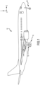
- the aircraft 10 includes landing gear, which may include a left main landing gear 12, a right main landing gear 14 and a nose landing gear 16.
- the landing gear support the aircraft 10 when it is not flying, allowing the aircraft 10 to taxi, take off and land without damage. While the disclosure refers to the three landing gear configurations just referred, the disclosure nevertheless contemplates any number of landing gear configurations.
- an aircraft 100 includes multiple landing gear systems, including a first landing gear 110, second landing gear 120, and third landing gear 130 is illustrated.
- the first landing gear 110, second landing gear 120, and third landing gear 130 each include one or more wheel assemblies.
- the second landing gear 120 which is also a nose landing gear for the aircraft 100, includes a left wheel assembly 16l and a right wheel assembly 16r.
- the first landing gear 110 includes an inboard wheel assembly 12i and an outer wheel assembly 12o
- the third landing gear 130 includes an inner wheel assembly 14i and an outer wheel assembly 14o.
- the first landing gear 110, second landing gear 120, and third landing gear 130 support the aircraft 100 when the aircraft 100 is not flying, thereby allowing the aircraft 100 to take off, land, and taxi without damaging the aircraft 100.
- the second landing gear 120 is also a nose landing gear for the aircraft 100, and often times, one or more of the first landing gear 110, second landing gear 120, and third landing gear 130 are operationally retractable into the aircraft 100 when the aircraft 100 is in flight and/or airborne.
- the aircraft 100 further includes an avionics unit 140, which includes one or more controllers (e.g., processors) and one or more tangible, non-transitory memories capable of implementing digital or programmatic logic.
- the one or more controllers are one or more of a general-purpose processor, digital signal processor (DSP), application specific integrated circuit (ASIC), field programmable gate array (FPGA), or other programmable logic device, discrete gate, transistor logic, or discrete hardware components, or any various combinations thereof or the like.
- the avionics unit 140 controls, at least various parts of, the flight of, and operation of various components of, the aircraft 100.
- the BCU 150 controls, at least various parts of, the braking of the aircraft 100.
- the BCU 150 controls various parameters of braking, such as manual brake control, automatic brake control, antiskid braking, locked wheel protection, touchdown protection, park capability, gear retraction braking, and the like.
- the aircraft 100 further includes one or more brakes coupled to each wheel assembly.
- a brake 160 is coupled to the outer wheel assembly 14o of the third landing gear 130 of the aircraft 100.
- the brake 160 applies a braking force to the outer wheel assembly 14o upon receiving a brake command, such as from the BCU 150.
- the outer wheel assembly 14o of the third landing gear 130 of the aircraft 100 includes any number of wheels.
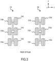
- the wheels are symmetrically controlled based on the wheel's position, i.e., which row (in a z-direction) and whether the wheel is inboard or outboard. Therefore, in FIG. 3 , front wheel assembly 312fi is symmetric with front wheel assembly 314fi, front wheel assembly 312fo is symmetric with front wheel assembly 314fo, center wheel assembly 312ci is symmetric with center wheel assembly 314ci, center wheel assembly 312co is symmetric with center wheel assembly 314co, rear wheel assembly 312ri is symmetric with rear wheel assembly 314ri, and rear wheel assembly 312ro is symmetric with rear wheel assembly 314ro.
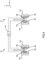
- FIG. 4 a front view of landing gears with a plurality of a wheel sets is illustrated.
- the front wheel assemblies 312fo, 312fi, 314fi, and 314fo are depicted. However, the operations described hereafter with regard to the front wheel assemblies 312fo, 312fi, 314fi, and 314fo operates similarly with regard to the center wheel assemblies 312co, 312ci, 314ci, and 314co and the rear wheel assemblies 312ro, 312ri, 314ri, and 314ro.
- I w the inertia, i.e. the moment of inertia of the wheel, brake and tire
- ⁇ is the angular acceleration of the wheel
- T fr is the torque exerted on a wheel due to frictional drag of the runway
- the brake torque T brake is obtained as:
- T brake K brake F brake
- K brake is a constant multiplier that converts the actuator force to torque. This constant depends on the brake friction coefficients ( ⁇ brake ) and number of brake friction surfaces.
- equations 1 and 2 illustrate that the wheel deceleration and the corresponding brake force are closely related to the brake's coefficient of friction ( ⁇ ) value. That is, in various embodiments, the higher the brake torque, the lower the wheel angular deceleration.
- the BCU 150 determines wheel angular deceleration for each of the front wheel assemblies 312fo, 312fi, 314fi, and 314fo through the differentiation of an angular wheel speed transducer signal and applied brake force.
- each of front wheel assemblies 312fo, 312fi, 314fi, and 314fo comprises a brake assemblies 160a, 160b, 160c, or 160d, respectively, and a wheel speed transducer 402a, 402b, 402c, or 402d, respectively.
- each of the wheel speed transducers 402a, 402b, 402c, and 402d which may also be referred to as a wheel speed sensor, measures a rotation of its associated wheel.
- the brake control unit (BCU) 150 receives an indication of wheel speed from each of the wheel speed transducers 402a, 402b, 402c, and 402d.
- the BCU 150 may receive a deceleration of each of front wheel assemblies 312fo, 312fi, 314fi, and 314fo from each of the wheel speed transducers 402a, 402b, 402c, and 402d as the brakes are being applied to the wheel.
- the BCU 150 responsive to the BCU 150 determining that the comparisons are all within a predetermined range of the average deceleration of the four front wheel assemblies 312fo, 312fi, 314fi, and 314fo, the BCU 150 identifies that all brakes are functioning in a similar manner and no issues are reported.
- the predetermined range may be ⁇ 20%. In various embodiments, the predetermined range may be ⁇ 15%. In various embodiments, the predetermined range may be ⁇ 10%.
- the BCU 150 may compare the deceleration of the one or more four front wheel assemblies 312fo, 312fi, 314fi, and 314fo with respect to the average deceleration of the four front wheel assemblies 312fo, 312fi, 314fi, and 314fo over a predetermined number of taxi events and store the data in a memory to calculate the trend of out of tolerance differences.
- the BCU 150 determines that a deceleration of one or more of the four front wheel assemblies 312fo, 312fi, 314fi, and 314fo was outside the predetermined range of the average deceleration of the four front wheel assemblies 312fo, 312fi, 314fi, and 314fo but has returned to within the predetermined range of the average deceleration of the four front wheel assemblies 312fo, 312fi, 314fi, and 314fo, then the BCU 150 identified no issues.
- the BCU 150 reports a warning message to the maintenance crew to inspect the one or more of brake assemblies 160a, 160b, 160c, or 160d.
- the BCU 150 may also utilize information obtained from the development and qualification of the one or more of brake assemblies 160a, 160b, 160c, or 160d.
- brake information may be obtained during development, i.e. wheel deceleration or brake force (or pressure) applied for various wheel speeds, among others, of the four front wheel assemblies 312fo, 312fi, 314fi, and 314fo.
- a wheel deceleration to brake force ratio may be defined at various wheel speeds, which the BCU 150 stores in a memory.
- the BCU 150 calculates a ratio of deceleration to brake force for each of the four front wheel assemblies 312fo, 312fi, 314fi, and 314fo and compares to the pre-stored values of deceleration to brake force in memory. In various embodiments, responsive to the BCU 150 determining that the ratio of deceleration to brake force for each wheel and to the pre-stored values of deceleration to brake force in memory is within a predetermined range, the BCU 150 identifies that all brakes are functioning in a similar manner and no issues are reported.
- the predetermined range may be ⁇ 25 %. In various embodiments, the predetermined range may be ⁇ 22 %. In various embodiments, the predetermined range may be ⁇ 20 %.
- the BCU 150 may compare the deceleration to brake force for each of the four front wheel assemblies 312fo, 312fi, 314fi, and 314fo to the pre-stored values of deceleration to brake force for each of the four front wheel assemblies 312fo, 312fi, 314fi, and 314fo stored in a memory to calculate the trend of out of tolerance differences.
- the BCU 150 responsive to a trend being unconfirmed after the predetermined number of taxi events, i.e. the BCU 150 determines that the ratio of deceleration to brake force for each of the four front wheel assemblies 312fo, 312fi, 314fi, and 314fo to the pre-stored values of deceleration to brake force in memory was outside the predetermined range but has returned to within the predetermined range, then the BCU 150 identified no issues. However, in various embodiments, responsive to a trend being confirmed after the predetermined number of taxi events, then the BCU 150 reports a warning message to the maintenance crew to inspect the one or more of brake assemblies 160a, 160b, 160c, or 160d.
- the BCU 150 commands control of the deceleration of the aircraft's center of gravity by applying a common force to all brakes. Because various brakes have higher coefficient of friction ( ⁇ ) and other brakes have a lower coefficient of friction ( ⁇ ), in various embodiments, responsive to the BCU 150 commanding a common force to all brakes, various ones of the brakes may, in aggregate, do more work, which may be defined as energy dissipated in the brake in Joules (J), while various other ones of the brakes may, in aggregate, do less work.
- J energy dissipated in the brake in Joules
- the BCU 150 commanding a common force to each of the one or more of brake assemblies 160a, 160b, 160c, or 160d may cause controllability issues during braking and various brakes may absorb more energy and other brakes may absorb less energy at the end of a landing resulting with the colder brakes potentially wearing out faster than brakes having a same coefficient of friction ( ⁇ ) and causing premature oxidation issues on the hotter brakes.
- the BCU 150 calculates the average wheel deceleration of all of the four front wheel assemblies 312fo, 312fi, 314fi, and 314fo. In various embodiments, the BCU 150 compares the specific deceleration of each of the four front wheel assemblies 312fo, 312fi, 314fi, and 314fo to the average wheel deceleration of all of the four front wheel assemblies 312fo, 312fi, 314fi, and 314fo.
- the BCU 150 may estimate the "work," as described above, of a wheel by computing a slip associated with each of the four front wheel assemblies 312fo, 312fi, 314fi, and 314fo.
- one difficulty with estimating accurately the slip of a wheel is knowing the rolling radius of each of the four front wheel assemblies 312fo, 312fi, 314fi, and 314fo.
- the BCU 150 utilizes an angular deceleration for each of the four front wheel assemblies 312fo, 312fi, 314fi, and 314fo, which is accurately measured by each of the wheel speed transducers 402a, 402b, 402c, and 402d and, therefore, does not require the wheel's rolling radius.
- the following deceleration of each wheel with respect to the average deceleration may result in: Brake LOB LIB RIB ROB Deceleration of each wheel with respect to the average 1.05 .96 1 1.01
- LOB is the left outer wheel assembly 160d
- LIB is the left inner wheel assembly 160c
- RIB is the right inner wheel assembly 160b
- ROB is the right outer wheel assembly 160a.
- the front wheel assembly 312fo associated with the left outer brake (LOB) assembly 160d and front wheel assembly 314fo associated with the right outer brake (ROB) assembly 160a are decelerating more than the average, i.e.
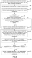
- Method 500 may be performed by processor within a brake control unit (BCU), such as BCU 150 of FIG. 2 .
- BCU brake control unit
- the BCU receives a deceleration of each wheel assembly of a plurality of wheel assemblies from an associated wheel speed transducer as the brakes are being applied to the respective wheel assembly. Responsive to the aircraft traveling in a substantially straight line and receiving a braking command, meaning the left and right pedal commands are similar, at block 504, the BCU compares each deceleration of each wheel assembly to an average deceleration of the plurality of wheel assemblies.
- the BCU determines whether one or more of the decelerations of the four wheels is outside the predetermined range of the average deceleration of the plurality of wheel assemblies. If at block 506 the BCU identifies that the decelerations of the four wheels are within predetermined range of the average deceleration of the plurality of wheel assemblies, at block 508, the BCU identifies that all brakes are functioning in a similar manner and no issues are reported, with the operation returning to block 502 thereafter.
- the BCU determines whether the trend indicates a confirmation of an issue with one or more brake assemblies associated with the one or more wheel assemblies. If at block 514 the BCU identifies that the trend is unconfirmed after the predetermined number of taxi events, the operation proceeds to block 508. If at block 514 the BCU identifies that the trend is confirmed after the predetermined number of taxi events, at block 516, the BCU reports a warning message to the maintenance crew to inspect the one or more of brake assemblies.
- Method 600 may be performed by processor within a brake control unit (BCU), such as BCU 150 of FIG. 2 .
- BCU brake control unit
- the BCU receives and stores brake information obtained from the development and qualification of one or more of brake assemblies.
- the brake information may include wheel deceleration or brake force (or pressure) applied for various wheel speeds, among others.
- the BCU defines a wheel deceleration to brake force ratio.
- the BCU calculates a ratio of deceleration to brake force for each wheel assembly of a plurality of wheel assemblies and, at block 608, the BCU determines whether the ratio of deceleration to brake force for each wheel and to the pre-stored values of deceleration to brake force in memory is within a predetermined range.
- the BCU determines that the ratio of deceleration to brake force for each wheel as compared to the defined values of deceleration to brake force in memory is within a predetermined range, at block 610, the BCU identifies that all brakes are functioning in a similar manner and no issues are reported, with the operation returning to block 602 thereafter.
- the BCU determines that the ratio of deceleration to brake force for each wheel and to the pre-stored values of deceleration to brake force in memory is outside the predetermined range.
- the BCU compares the deceleration to brake force for each of the plurality of wheel assemblies to the pre-stored values of deceleration to brake force for each of the plurality of wheel assemblies.
- the BCU calculates a trend of out of tolerance differences after the predetermined number of taxi events.
- the BCU determines whether the trend indicates a confirmation of an issue with one or more brake assemblies associated with the one or more wheel assemblies.
- the operation proceeds to block 610. If at block 616 the BCU identifies that the trend is confirmed after the predetermined number of taxi events, at block 618, the BCU reports a warning message to the maintenance crew to inspect the one or more of brake assemblies.
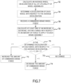
- Method 700 may be performed by processor within a brake control unit (BCU), such as BCU 150 of FIG. 2 .
- BCU brake control unit
- the BCU calculates the average wheel deceleration of all of a plurality of wheel assemblies.
- the BCU receives a commanded brake wheel force.
- the BCU determines a deceleration of each wheel with respect to the average deceleration is less than 1, at block 714, the BCU decreases the amount of commanded brake force. If at block 710 the BCU determines a deceleration of each wheel with respect to the average deceleration is equal to 1, at block 716, the BCU makes not change to the amount of commanded brake force.
- Numbers, percentages, or other values stated herein are intended to include that value, and also other values that are about or approximately equal to the stated value, as would be appreciated by one of ordinary skill in the art encompassed by various embodiments of the present disclosure.
- a stated value should therefore be interpreted broadly enough to encompass values that are at least close enough to the stated value to perform a desired function or achieve a desired result.
- the stated values include at least the variation to be expected in a suitable industrial process, and may include values that are within 10%, within 5%, within 1%, within 0.1%, or within 0.01% of a stated value.
- the terms “substantially,” “about,” or “approximately” as used herein represent an amount close to the stated amount that still performs a desired function or achieves a desired result.
- the term “substantially,” “about,” or “approximately” may refer to an amount that is within 10% of, within 5% of, within 1% of, within 0.1% of, and within 0.01% of a stated amount or value
Landscapes
- Engineering & Computer Science (AREA)
- Transportation (AREA)
- Mechanical Engineering (AREA)
- Aviation & Aerospace Engineering (AREA)
- Manufacturing & Machinery (AREA)
- Regulating Braking Force (AREA)
Applications Claiming Priority (1)
| Application Number | Priority Date | Filing Date | Title |
|---|---|---|---|
| US18/544,839 US12576823B2 (en) | 2023-12-19 | 2023-12-19 | Brake coefficient of friction (μ) estimation for prognostics and health management (PHM) and improved load balance (LB) |
Publications (1)
| Publication Number | Publication Date |
|---|---|
| EP4574595A1 true EP4574595A1 (de) | 2025-06-25 |
Family
ID=93741913
Family Applications (1)
| Application Number | Title | Priority Date | Filing Date |
|---|---|---|---|
| EP24216295.6A Pending EP4574595A1 (de) | 2023-12-19 | 2024-11-28 | Bremse reibungskoeffizient (ì) schätzung für prognose und health monitoring management (phm) und verbesserte lastbalance (lb) |
Country Status (2)
| Country | Link |
|---|---|
| US (1) | US12576823B2 (de) |
| EP (1) | EP4574595A1 (de) |
Cited By (1)
| Publication number | Priority date | Publication date | Assignee | Title |
|---|---|---|---|---|
| US20250196828A1 (en) * | 2023-12-19 | 2025-06-19 | Goodrich Corporation | BRAKE COEFFICIENT OF FRICTION (µ) ESTIMATION FOR PROGNOSTICS AND HEALTH MANAGEMENT (PHM) AND IMPROVED LOAD BALANCE (LB) |
Citations (3)
| Publication number | Priority date | Publication date | Assignee | Title |
|---|---|---|---|---|
| US3920204A (en) * | 1974-11-11 | 1975-11-18 | Boeing Co | Rejected take-off (RTO) control for automatic braking system |
| US4061403A (en) * | 1976-09-29 | 1977-12-06 | General Motors Corporation | Wheel lock control system |
| EP0601365B1 (de) * | 1992-12-08 | 1998-01-21 | Eaton Corporation | Verfahren und Vorrichtung zum Ermitteln des Service-Zeitpunktes für ein Kraftfahrzeugbremssystem |
Family Cites Families (30)
| Publication number | Priority date | Publication date | Assignee | Title |
|---|---|---|---|---|
| US3917356A (en) * | 1973-09-06 | 1975-11-04 | Boeing Co | Aircraft automatic braking system |
| US4076331A (en) * | 1973-09-06 | 1978-02-28 | The Boeing Company | Aircraft automatic braking system |
| US3920282A (en) * | 1973-09-06 | 1975-11-18 | Boeing Co | Aircraft automatic braking system |
| US3847445A (en) * | 1973-11-12 | 1974-11-12 | Boeing Co | Aircraft automatic braking system having auto-brake control logic |
| US4078845A (en) | 1976-08-13 | 1978-03-14 | The Boeing Company | Limited-slip brake control system |
| US5343396A (en) * | 1992-04-29 | 1994-08-30 | Youngblood Richard J | Sensor malfunction detection |
| US5390990A (en) * | 1993-11-24 | 1995-02-21 | Hydro-Aire Division Of Crane Company | Brake energy balancing system for multiple brake units |
| GB0019250D0 (en) * | 2000-08-04 | 2000-09-27 | Dunlop Aerospace Ltd | Monitoring brake application |
| EP1970274B1 (de) * | 2000-08-04 | 2014-01-08 | Meggitt Aerospace Limited | Bremsenzustandsüberwachung |
| US7410224B2 (en) * | 2006-01-19 | 2008-08-12 | Hydro-Aire, Inc. | Method and system to increase electric brake clamping force accuracy |
| GB2439742A (en) | 2006-07-05 | 2008-01-09 | Dunlop Aerospace Ltd | Symmetrical braking control system in aircraft |
| US8102280B2 (en) * | 2009-03-03 | 2012-01-24 | Goodrich Corporation | System and method for detecting a dragging brake |
| US8180548B2 (en) | 2009-04-24 | 2012-05-15 | Goodrich Corporation | Deceleration controlled braking |
| US8634971B2 (en) * | 2009-05-05 | 2014-01-21 | Goodrich Corporation | Brake wear control system |
| US8712626B2 (en) * | 2009-05-05 | 2014-04-29 | Goodrich Corporation | Autobrake and decel control built-in test equipment |
| US8843254B2 (en) * | 2012-07-11 | 2014-09-23 | Goodrich Corporation | Systems and methods for dragging brake detection |
| US9296488B2 (en) | 2013-03-06 | 2016-03-29 | 3Rd Millennium Solutions, Inc. | Aircraft braking early warning system |
| US20150012201A1 (en) * | 2013-07-03 | 2015-01-08 | Goodrich Corporation | Brake control system comprising runway friction property estimation mapping |
| KR101583926B1 (ko) * | 2014-05-12 | 2016-01-08 | 현대자동차주식회사 | 요레이트를 이용한 제동장치 고장 검출방법 |
| DE102014225448B4 (de) * | 2014-12-10 | 2024-10-24 | Bayerische Motoren Werke Aktiengesellschaft | Verfahren und Vorrichtung zum Erkennen ungewollt blockierender Räder durch Fehler im Antriebssystem |
| US9981754B2 (en) * | 2015-11-13 | 2018-05-29 | Goodrich Corporation | System and method for detecting bad runway conditions |
| US10005566B2 (en) * | 2016-06-13 | 2018-06-26 | Goodrich Corporation | Systems and methods for detection of dragging brake |
| US10800392B2 (en) * | 2017-04-18 | 2020-10-13 | The Boeing Company | Brake health indicator systems using input and output energy |
| US10300897B2 (en) | 2017-05-15 | 2019-05-28 | Goodrich Corporation | Brake load balance and runway centering techniques |
| US10882500B2 (en) * | 2018-11-30 | 2021-01-05 | Raytheon Technologies Corporation | Systems and methods for brake failure detection using retract braking |
| JP7560458B2 (ja) * | 2018-12-11 | 2024-10-02 | イーグル エアロスペース,リミテッド | 航空機の着陸および地表面移動性能を評価するための方法およびソフトウェアプログラム |
| US11505173B2 (en) * | 2020-03-13 | 2022-11-22 | Goodrich Corporation | Systems and methods for brake health monitoring |
| US12128863B2 (en) * | 2020-05-11 | 2024-10-29 | Goodrich Corporation | Detection of brake failure using wheel speed during landing gear retraction |
| US12576823B2 (en) * | 2023-12-19 | 2026-03-17 | Goodrich Corporation | Brake coefficient of friction (μ) estimation for prognostics and health management (PHM) and improved load balance (LB) |
| CN118220478A (zh) * | 2024-03-29 | 2024-06-21 | 西安航空制动科技有限公司 | 一种基于跑道识别的飞机自动刹车系统及方法 |
-
2023
- 2023-12-19 US US18/544,839 patent/US12576823B2/en active Active
-
2024
- 2024-11-28 EP EP24216295.6A patent/EP4574595A1/de active Pending
Patent Citations (3)
| Publication number | Priority date | Publication date | Assignee | Title |
|---|---|---|---|---|
| US3920204A (en) * | 1974-11-11 | 1975-11-18 | Boeing Co | Rejected take-off (RTO) control for automatic braking system |
| US4061403A (en) * | 1976-09-29 | 1977-12-06 | General Motors Corporation | Wheel lock control system |
| EP0601365B1 (de) * | 1992-12-08 | 1998-01-21 | Eaton Corporation | Verfahren und Vorrichtung zum Ermitteln des Service-Zeitpunktes für ein Kraftfahrzeugbremssystem |
Cited By (2)
| Publication number | Priority date | Publication date | Assignee | Title |
|---|---|---|---|---|
| US20250196828A1 (en) * | 2023-12-19 | 2025-06-19 | Goodrich Corporation | BRAKE COEFFICIENT OF FRICTION (µ) ESTIMATION FOR PROGNOSTICS AND HEALTH MANAGEMENT (PHM) AND IMPROVED LOAD BALANCE (LB) |
| US12576823B2 (en) * | 2023-12-19 | 2026-03-17 | Goodrich Corporation | Brake coefficient of friction (μ) estimation for prognostics and health management (PHM) and improved load balance (LB) |
Also Published As
| Publication number | Publication date |
|---|---|
| US20250196828A1 (en) | 2025-06-19 |
| US12576823B2 (en) | 2026-03-17 |
Similar Documents
| Publication | Publication Date | Title |
|---|---|---|
| EP3875323B1 (de) | Systeme und verfahren zum antiblockierbremsen eines flugzeugs | |
| EP3693236B1 (de) | Bremslastausgleich und landebahnzentriertechniken | |
| US10759524B2 (en) | Antiskid operation during degraded operation | |
| EP3556619B1 (de) | Energiebasiertes antiblockierbremssteuerungssystem | |
| EP3653456B1 (de) | System und verfahren zur antirutsch-initialisierung mit schneller konvergenz | |
| EP4180287B1 (de) | Systeme und verfahren zur überwachung des zustands von bremsen | |
| EP4574595A1 (de) | Bremse reibungskoeffizient (ì) schätzung für prognose und health monitoring management (phm) und verbesserte lastbalance (lb) | |
| EP3712021B1 (de) | Systeme und verfahren für antiblockiertolerante multimodus-autobremsensteuerung | |
| US10710561B2 (en) | Deceleration pedal control for braking systems | |
| EP3964409B1 (de) | Systeme und verfahren zur betätigung von niedriggeschwindigkeitsbremse | |
| EP3900989B1 (de) | Systeme und verfahren zur steuerung einer automatischen flugzeugbremse | |
| EP2567873B1 (de) | Systeme und Verfahren für verbesserte Flugzeugbremsen | |
| EP4360970A1 (de) | Erweiterte sperrradschutzfunktionalität |
Legal Events
| Date | Code | Title | Description |
|---|---|---|---|
| PUAI | Public reference made under article 153(3) epc to a published international application that has entered the european phase |
Free format text: ORIGINAL CODE: 0009012 |
|
| STAA | Information on the status of an ep patent application or granted ep patent |
Free format text: STATUS: THE APPLICATION HAS BEEN PUBLISHED |
|
| AK | Designated contracting states |
Kind code of ref document: A1 Designated state(s): AL AT BE BG CH CY CZ DE DK EE ES FI FR GB GR HR HU IE IS IT LI LT LU LV MC ME MK MT NL NO PL PT RO RS SE SI SK SM TR |
|
| STAA | Information on the status of an ep patent application or granted ep patent |
Free format text: STATUS: REQUEST FOR EXAMINATION WAS MADE |
|
| 17P | Request for examination filed |
Effective date: 20251105 |