EP4574604A1 - Fahrzeugsteuerungsvorrichtung - Google Patents
Fahrzeugsteuerungsvorrichtung Download PDFInfo
- Publication number
- EP4574604A1 EP4574604A1 EP24214909.4A EP24214909A EP4574604A1 EP 4574604 A1 EP4574604 A1 EP 4574604A1 EP 24214909 A EP24214909 A EP 24214909A EP 4574604 A1 EP4574604 A1 EP 4574604A1
- Authority
- EP
- European Patent Office
- Prior art keywords
- vehicle
- crossing target
- target
- crossing
- satisfied
- Prior art date
- Legal status (The legal status is an assumption and is not a legal conclusion. Google has not performed a legal analysis and makes no representation as to the accuracy of the status listed.)
- Pending
Links
Images






Classifications
-
- B—PERFORMING OPERATIONS; TRANSPORTING
- B60—VEHICLES IN GENERAL
- B60W—CONJOINT CONTROL OF VEHICLE SUB-UNITS OF DIFFERENT TYPE OR DIFFERENT FUNCTION; CONTROL SYSTEMS SPECIALLY ADAPTED FOR HYBRID VEHICLES; ROAD VEHICLE DRIVE CONTROL SYSTEMS FOR PURPOSES NOT RELATED TO THE CONTROL OF A PARTICULAR SUB-UNIT
- B60W30/00—Purposes of road vehicle drive control systems not related to the control of a particular sub-unit, e.g. of systems using conjoint control of vehicle sub-units
- B60W30/08—Active safety systems predicting or avoiding probable or impending collision or attempting to minimise its consequences
- B60W30/095—Predicting travel path or likelihood of collision
- B60W30/0956—Predicting travel path or likelihood of collision the prediction being responsive to traffic or environmental parameters
-
- B—PERFORMING OPERATIONS; TRANSPORTING
- B60—VEHICLES IN GENERAL
- B60T—VEHICLE BRAKE CONTROL SYSTEMS OR PARTS THEREOF; BRAKE CONTROL SYSTEMS OR PARTS THEREOF, IN GENERAL; ARRANGEMENT OF BRAKING ELEMENTS ON VEHICLES IN GENERAL; PORTABLE DEVICES FOR PREVENTING UNWANTED MOVEMENT OF VEHICLES; VEHICLE MODIFICATIONS TO FACILITATE COOLING OF BRAKES
- B60T7/00—Brake-action initiating means
- B60T7/12—Brake-action initiating means for automatic initiation; for initiation not subject to will of driver or passenger
- B60T7/22—Brake-action initiating means for automatic initiation; for initiation not subject to will of driver or passenger initiated by contact of vehicle, e.g. bumper, with an external object, e.g. another vehicle, or by means of contactless obstacle detectors mounted on the vehicle
-
- B—PERFORMING OPERATIONS; TRANSPORTING
- B60—VEHICLES IN GENERAL
- B60T—VEHICLE BRAKE CONTROL SYSTEMS OR PARTS THEREOF; BRAKE CONTROL SYSTEMS OR PARTS THEREOF, IN GENERAL; ARRANGEMENT OF BRAKING ELEMENTS ON VEHICLES IN GENERAL; PORTABLE DEVICES FOR PREVENTING UNWANTED MOVEMENT OF VEHICLES; VEHICLE MODIFICATIONS TO FACILITATE COOLING OF BRAKES
- B60T7/00—Brake-action initiating means
- B60T7/12—Brake-action initiating means for automatic initiation; for initiation not subject to will of driver or passenger
-
- B—PERFORMING OPERATIONS; TRANSPORTING
- B60—VEHICLES IN GENERAL
- B60W—CONJOINT CONTROL OF VEHICLE SUB-UNITS OF DIFFERENT TYPE OR DIFFERENT FUNCTION; CONTROL SYSTEMS SPECIALLY ADAPTED FOR HYBRID VEHICLES; ROAD VEHICLE DRIVE CONTROL SYSTEMS FOR PURPOSES NOT RELATED TO THE CONTROL OF A PARTICULAR SUB-UNIT
- B60W30/00—Purposes of road vehicle drive control systems not related to the control of a particular sub-unit, e.g. of systems using conjoint control of vehicle sub-units
- B60W30/08—Active safety systems predicting or avoiding probable or impending collision or attempting to minimise its consequences
- B60W30/09—Taking automatic action to avoid collision, e.g. braking and steering
-
- B—PERFORMING OPERATIONS; TRANSPORTING
- B60—VEHICLES IN GENERAL
- B60W—CONJOINT CONTROL OF VEHICLE SUB-UNITS OF DIFFERENT TYPE OR DIFFERENT FUNCTION; CONTROL SYSTEMS SPECIALLY ADAPTED FOR HYBRID VEHICLES; ROAD VEHICLE DRIVE CONTROL SYSTEMS FOR PURPOSES NOT RELATED TO THE CONTROL OF A PARTICULAR SUB-UNIT
- B60W30/00—Purposes of road vehicle drive control systems not related to the control of a particular sub-unit, e.g. of systems using conjoint control of vehicle sub-units
- B60W30/08—Active safety systems predicting or avoiding probable or impending collision or attempting to minimise its consequences
- B60W30/095—Predicting travel path or likelihood of collision
- B60W30/0953—Predicting travel path or likelihood of collision the prediction being responsive to vehicle dynamic parameters
-
- B—PERFORMING OPERATIONS; TRANSPORTING
- B60—VEHICLES IN GENERAL
- B60W—CONJOINT CONTROL OF VEHICLE SUB-UNITS OF DIFFERENT TYPE OR DIFFERENT FUNCTION; CONTROL SYSTEMS SPECIALLY ADAPTED FOR HYBRID VEHICLES; ROAD VEHICLE DRIVE CONTROL SYSTEMS FOR PURPOSES NOT RELATED TO THE CONTROL OF A PARTICULAR SUB-UNIT
- B60W30/00—Purposes of road vehicle drive control systems not related to the control of a particular sub-unit, e.g. of systems using conjoint control of vehicle sub-units
- B60W30/18—Propelling the vehicle
- B60W30/18009—Propelling the vehicle related to particular drive situations
- B60W30/18154—Approaching an intersection
-
- B—PERFORMING OPERATIONS; TRANSPORTING
- B60—VEHICLES IN GENERAL
- B60W—CONJOINT CONTROL OF VEHICLE SUB-UNITS OF DIFFERENT TYPE OR DIFFERENT FUNCTION; CONTROL SYSTEMS SPECIALLY ADAPTED FOR HYBRID VEHICLES; ROAD VEHICLE DRIVE CONTROL SYSTEMS FOR PURPOSES NOT RELATED TO THE CONTROL OF A PARTICULAR SUB-UNIT
- B60W30/00—Purposes of road vehicle drive control systems not related to the control of a particular sub-unit, e.g. of systems using conjoint control of vehicle sub-units
- B60W30/18—Propelling the vehicle
- B60W30/18009—Propelling the vehicle related to particular drive situations
- B60W30/18159—Traversing an intersection
-
- B—PERFORMING OPERATIONS; TRANSPORTING
- B60—VEHICLES IN GENERAL
- B60W—CONJOINT CONTROL OF VEHICLE SUB-UNITS OF DIFFERENT TYPE OR DIFFERENT FUNCTION; CONTROL SYSTEMS SPECIALLY ADAPTED FOR HYBRID VEHICLES; ROAD VEHICLE DRIVE CONTROL SYSTEMS FOR PURPOSES NOT RELATED TO THE CONTROL OF A PARTICULAR SUB-UNIT
- B60W60/00—Drive control systems specially adapted for autonomous road vehicles
- B60W60/001—Planning or execution of driving tasks
-
- G—PHYSICS
- G08—SIGNALLING
- G08G—TRAFFIC CONTROL SYSTEMS
- G08G1/00—Traffic control systems for road vehicles
- G08G1/16—Anti-collision systems
- G08G1/166—Anti-collision systems for active traffic, e.g. moving vehicles, pedestrians, bikes
-
- B—PERFORMING OPERATIONS; TRANSPORTING
- B60—VEHICLES IN GENERAL
- B60T—VEHICLE BRAKE CONTROL SYSTEMS OR PARTS THEREOF; BRAKE CONTROL SYSTEMS OR PARTS THEREOF, IN GENERAL; ARRANGEMENT OF BRAKING ELEMENTS ON VEHICLES IN GENERAL; PORTABLE DEVICES FOR PREVENTING UNWANTED MOVEMENT OF VEHICLES; VEHICLE MODIFICATIONS TO FACILITATE COOLING OF BRAKES
- B60T2201/00—Particular use of vehicle brake systems; Special systems using also the brakes; Special software modules within the brake system controller
- B60T2201/02—Active or adaptive cruise control system; Distance control
- B60T2201/022—Collision avoidance systems
-
- B—PERFORMING OPERATIONS; TRANSPORTING
- B60—VEHICLES IN GENERAL
- B60T—VEHICLE BRAKE CONTROL SYSTEMS OR PARTS THEREOF; BRAKE CONTROL SYSTEMS OR PARTS THEREOF, IN GENERAL; ARRANGEMENT OF BRAKING ELEMENTS ON VEHICLES IN GENERAL; PORTABLE DEVICES FOR PREVENTING UNWANTED MOVEMENT OF VEHICLES; VEHICLE MODIFICATIONS TO FACILITATE COOLING OF BRAKES
- B60T2210/00—Detection or estimation of road or environment conditions; Detection or estimation of road shapes
- B60T2210/30—Environment conditions or position therewithin
- B60T2210/32—Vehicle surroundings
-
- B—PERFORMING OPERATIONS; TRANSPORTING
- B60—VEHICLES IN GENERAL
- B60T—VEHICLE BRAKE CONTROL SYSTEMS OR PARTS THEREOF; BRAKE CONTROL SYSTEMS OR PARTS THEREOF, IN GENERAL; ARRANGEMENT OF BRAKING ELEMENTS ON VEHICLES IN GENERAL; PORTABLE DEVICES FOR PREVENTING UNWANTED MOVEMENT OF VEHICLES; VEHICLE MODIFICATIONS TO FACILITATE COOLING OF BRAKES
- B60T2250/00—Monitoring, detecting, estimating vehicle conditions
- B60T2250/04—Vehicle reference speed; Vehicle body speed
Definitions
- Related-art vehicle control devices including the vehicle control device as disclosed in Japanese Patent Application Laid-open No. 2018-111335 and capable of executing the deceleration control for the crossing target finishes the deceleration control when the collision between the own vehicle and the crossing target is reliably avoided during the execution of the deceleration control. For example, the deceleration control is finished when the crossing target is stopped or the crossing target has already crossed the predicted travel region of the own vehicle.
- the position of the crossing target is a position before crossing the predicted travel region of the own vehicle and the own vehicle and the crossing target are moving, there is a possibility that the own vehicle and the crossing target collide with each other depending on a subsequent behavior of the crossing target, and hence the deceleration control is not finished.
- the present disclosure has an object to provide a vehicle control device capable of solving the above-mentioned problem. That is, the present disclosure has an object to provide a vehicle control device capable of suppressing continuation of deceleration control when the continuation of the deceleration control is not required.
- a vehicle control device including: a braking device configured to brake an own vehicle; and a control unit configured to start deceleration control of controlling the braking device such that the own vehicle decelerates when the control unit determines that a probability of collision between the own vehicle and a crossing target that is a target predicted to cross a predicted travel region of the own vehicle is high, and to finish the deceleration control when a predetermined control finish condition is satisfied during the execution of the deceleration control.
- the predetermined control finish condition includes an avoidance condition which is a condition satisfaction or dissatisfaction of which is determined when a position of the crossing target is a position before crossing the predicted travel region of the own vehicle and the own vehicle and the crossing target are moving, and which is satisfied when a predetermined condition is satisfied.
- the predetermined condition is set based on an own vehicle passage predicted time that is a predicted time taken by the own vehicle to pass beyond an intersecting region, which is an intersection of the predicted travel region of the own vehicle and a predicted movement region of the crossing target, and a crossing target reaching predicted time that is a predicted time taken by the crossing target to reach the intersecting region.
- the avoidance condition is satisfied when the condition set based on the time taken by the own vehicle to pass beyond the intersecting region and the time taken by the crossing target to reach the intersecting region is satisfied.
- the control unit determines that the control finish condition is satisfied when the avoidance condition is satisfied during the execution of the deceleration control, and finishes the deceleration control.
- the own vehicle passage predicted time is a predicted time taken by the own vehicle to pass beyond the intersecting region from a current position when it is assumed that the own vehicle maintains a current speed
- the crossing target reaching predicted time is a predicted time taken by the crossing target to reach the intersecting region from a current position when it is assumed that the crossing target executes predetermined acceleration from a current speed
- the avoidance condition is a condition satisfied when the own vehicle passage predicted time is shorter than the crossing target reaching predicted time.
- the crossing target reaching predicted time is a predicted time taken by the crossing target to reach the intersecting region from the current position when it is assumed that the crossing target executes acceleration at a predetermined acceleration and a predetermined acceleration gradient from the current speed.
- the own vehicle passage predicted time is a predicted time taken by the own vehicle to pass beyond the intersecting region from a current position when it is assumed that the own vehicle maintains a current speed
- the crossing target reaching predicted time is a predicted time taken by the crossing target to reach the intersecting region from a current position when it is assumed that the crossing target maintains a current speed.
- the predetermined control finish condition includes a crossing target passage condition that is satisfied when the crossing target has passed beyond the intersecting region.
- the control unit determines that the control finish condition is satisfied when the crossing target passage condition is satisfied during the execution of the deceleration control, and hence can finish the deceleration control.
- the predetermined control finish condition includes a crossing target stop condition that is satisfied when the crossing target stops before reaching the intersecting region.
- the crossing target is highly probably waiting for the passage of the own vehicle at a position before reaching the intersecting region so that the own vehicle first passes beyond the intersecting region. In this case, the collision between the own vehicle and the crossing target in the intersecting region does not occur.
- the control unit determines that the control finish condition is satisfied when the crossing target stop condition is satisfied during the execution of the deceleration control, and hence can finish the deceleration control.
- a vehicle control device is mounted to a vehicle.
- the vehicle to which the vehicle control device according to the at least one embodiment of the present disclosure is mounted is hereinafter referred to as "own vehicle 100".
- own vehicle 100 a vehicle control device 1 according to the at least one embodiment is mounted to the own vehicle 100.
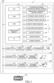
- the vehicle control device 1 includes a vehicle control ECU 10, an in-vehicle sensor 20, a drive device 30, a braking device 40, and a steering device 50.
- the drive device 30 generates a driving force, and applies this driving force to driving wheels of the own vehicle 100.
- the drive device 30 includes a drive ECU 31, a drive actuator 32, a drive source 33, a transmission 34, and a driving force transmission mechanism (not shown) which transmits the driving force to the driving wheels.
- the drive ECU 31 is electrically connected to the drive actuator 32 so that an operation of the drive actuator 32 can be controlled.
- the drive actuator 32 is configured to be able to adjust the driving force of the drive source 33 by being activated.
- the drive ECU 31 controls a driving force generated by the internal combustion engine.
- the drive ECU 31 controls a driving force generated by any one of or both of an internal combustion engine and an electric motor serving as the drive source 33.
- the drive ECU 31 controls a driving force generated by an electric motor serving as the drive source 33.
- This steering actuator 52 may also be configured to generate such a steering assist force as assisting in the operation of a driver on the steering wheel 53a.
- the steering ECU 51 controls an operation of the steering actuator 52, to thereby control the operation of the steering mechanism 53.
- the steering ECU 51 can control steering angles of the steered wheels of the own vehicle 100 by controlling the steering actuator 52.
- the accelerator pedal operation amount sensor 21 detects an operation amount of the accelerator pedal 35.
- the accelerator pedal operation amount sensor 21 is electrically connected to the vehicle control ECU 10.
- the accelerator pedal operation amount sensor 21 transmits information indicating the detected operation amount of the accelerator pedal 35 to the vehicle control ECU 10.
- the vehicle control ECU 10 acquires the operation amount of the accelerator pedal 35 based on the information received from the accelerator pedal operation amount sensor 21.
- the brake pedal operation amount sensor 22 detects an operation amount of the brake pedal 44.
- the brake pedal operation amount sensor 22 is electrically connected to the vehicle control ECU 10.
- the brake pedal operation amount sensor 22 transmits information indicating the detected operation amount of the brake pedal 44 to the vehicle control ECU 10.
- the vehicle control ECU 10 acquires the operation amount of the brake pedal 44 based on the information received from the brake pedal operation amount sensor 22.
- the steering angle sensor 23 detects a rotation angle of the steering shaft 53b with respect to a neutral position.
- the steering angle sensor 23 is electrically connected to the vehicle control ECU 10.
- the steering angle sensor 23 transmits information indicating the detected rotation angle of the steering shaft 53b to the vehicle control ECU 10.
- the vehicle control ECU 10 acquires the rotation angle of the steering shaft 53b as a steering angle ⁇ e based on the information received from the steering angle sensor 23.
- the steering torque sensor 24 detects a torque input by the driver to the steering shaft 53b via the steering wheel 53a.
- the steering torque sensor 24 is electrically connected to the vehicle control ECU 10.
- the steering torque sensor 24 transmits information indicating the detected torque to the vehicle control ECU 10.
- the vehicle control ECU 10 acquires, as a steering torque, the torque input by the driver to the steering shaft 53b via the steering wheel 53a based on the information received from the steering torque sensor 24.
- the yaw rate sensor 253 detects a yaw rate of the own vehicle 100.
- the yaw rate sensor 253 is electrically connected to the vehicle control ECU 10.
- the yaw rate sensor 253 transmits information indicating the detected yaw rate to the vehicle control ECU 10.
- the vehicle control ECU 10 acquires a yaw rate Y e of the own vehicle 100 based on the information received from the yaw rate sensor 253.
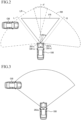
- the right front lateral radar sensor 261b transmits a radar wave to a region (right front lateral region) having an extension over a predetermined angle having, as a center, an axis R directed from the mounting position thereof toward a right front lateral (right diagonally front) direction of the own vehicle 100, and receives a reflected wave from the right front lateral region.
- a region (right front lateral region) RR in which the radar wave is transmitted by the right front lateral radar sensor 261b is schematically indicated as a region surrounded by the broken line.
- the front radar sensor 261a detects a target existing in the front region FR based on the relationship between the transmitted wave and the received wave, and transmits information on the detected target to the vehicle control ECU 10.
- the right front lateral radar sensor 261b detects a target existing in the right front lateral region RR based on the relationship between the transmitted wave and the received wave, and transmits information on the detected target to the vehicle control ECU 10.
- the left front lateral radar sensor 261c detects a target existing in the left front lateral region LR based on the relationship between the transmitted wave and the received wave, and transmits information on the detected target to the vehicle control ECU 10.
- the right front lateral and left front lateral are sometimes collectively referred to as "front lateral”.
- the right front lateral radar sensor 261b and the left front lateral radar sensor 261c are sometimes collectively referred to as "front lateral radar sensors 261s”.
- the camera sensor 262 includes a front camera sensor 262a.
- FIG. 3 shows a position at which the front camera sensor 262a is mounted to the own vehicle 100.
- the front camera sensor 262a is installed at, for example, a center of an upper portion of a front windshield of the own vehicle 100.
- An image pickup lens provided to a camera device of the front camera sensor 262a is a wide angle lens, and hence the front camera sensor 262a can capture an image of a relatively wide region, for example, the front region and the front lateral regions in front of the own vehicle 100.
- the vehicle control ECU 10 is connected, via a controller area network (CAN), to other ECUs including the drive ECU 31, the braking ECU 41, and the steering ECU 51 such that information can mutually be transmitted and received.
- CAN controller area network
- each ECU can acquire, via the CAN, information acquired by the other ECUs.
- the vehicle control device 1 is configured to be able to execute automatic driving control for the own vehicle 100.
- the vehicle control ECU 10 transmits, via the CAN, a control signal to each of the drive ECU 31, the braking ECU 41, and the steering ECU 51 based on the information acquired from the in-vehicle sensor 20.
- the drive ECU 31 controls the drive actuator 32 based on the control signal received from the vehicle control ECU 10.
- the braking ECU 41 controls the braking actuator 42 based on the control signal received from the vehicle control ECU 10.
- the steering ECU 51 controls the steering actuator 52 based on the control signal received from the vehicle control ECU 10.
- the vehicle control ECU 10 starts automatic brake control when the vehicle control ECU 10 determines that a probability of collision between the own vehicle 100 and a target (crossing target) predicted to cross a region (predicted travel region) in which the own vehicle 100 is predicted to travel is high.
- the vehicle control ECU 10 calculates the predicted travel region of the own vehicle 100 during the travel of the own vehicle 100.
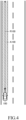
- FIG. 4 shows the predicted travel region of the own vehicle 100.
- the predicted travel region of the own vehicle 100 is a region in which the own vehicle 100 is predicted to travel subsequently to the current time.
- a predicted travel region A100 is a region having a center at a predicted travel path R100 of the own vehicle 100 and having a width equivalent to a vehicle width of the own vehicle 100.
- the predicted travel path R100 is a travel path on which a center portion of the own vehicle 100 in the vehicle width direction is predicted to travel when the own vehicle 100 travels while maintaining a steering angle ⁇ e or yaw rate Y e at the current time.
- the predicted travel path R100 illustrated in FIG. 4 is in a straight-line shape, but may be in a curved shape depending on a situation.
- the vehicle control ECU 10 calculates the predicted travel path R100 which is the path on which the center portion of the own vehicle 100 in the width direction is predicted to travel based on the own vehicle speed V e , the acceleration ⁇ e , and the steering angle ⁇ e (or the yaw rate Y e ). Moreover, the vehicle control ECU 10 calculates the predicted travel region A100 based on the calculated predicted travel path R100 and the vehicle width of the own vehicle 100.
- the vehicle control ECU 10 determines whether or not a moving target exists in the front region or the front lateral regions of the own vehicle 100 based on the information acquired from the front radar sensor 261a and the front lateral radar sensors 261s, and the front camera sensor 262a during the travel of the own vehicle 100.
- the vehicle control ECU 10 determines that a moving target exists in the front region or the front lateral regions of the own vehicle 100
- the vehicle control ECU 10 calculates a predicted movement region of this moving target.
- the predicted movement region of the moving target is a region in which the moving target travels along a path on which the moving target is predicted to travel.
- the predicted travel region A100 of the own vehicle 100 and the predicted movement region of the moving target can be expressed on a predetermined two-dimensional coordinate plane.
- the predicted travel region A100 of the own vehicle 100 and the predicted movement region of the moving target can be expressed on an X-Y coordinate plane having an origin at a predetermined position of the own vehicle 100 (for example, the center portion of the front end of the own vehicle 100), an X axis which passes through the origin and extends along the front-and-rear direction of the own vehicle 100, and a Y axis which passes through the origin and extends along the width direction of the own vehicle 100.
- the vehicle control ECU 10 determines whether or not the predicted travel region A100 of the own vehicle 100 and the predicted movement region of the moving target expressed on this X-Y coordinate plane intersect with each other. When the vehicle control ECU 10 determines that the predicted travel region A100 of the own vehicle 100 and the predicted movement region of the moving target intersect with each other, the vehicle control ECU 10 sets this moving target as a crossing target 200 which is predicted to cross the predicted travel region A100 of the own vehicle 100.
- FIG. 5 shows the predicted travel region A100 of the own vehicle 100 and a predicted movement region A200 of the crossing target 200 expressed on the X-Y coordinate plane.
- the origin O of the X-Y coordinate plane of FIG. 5 is the center portion of the front end of the own vehicle 100, the X axis passes through the origin O and extends in the front-and-rear direction of the own vehicle 100, and the Y axis passes through the origin O and extends in the width direction of the own vehicle 100.
- a region on an upper right side of the origin O is a region in which X>0 and Y>0.
- a region on an upper left side of the origin O is a region in which X>0 and Y ⁇ 0.
- a region on a lower right side of the origin O is a region in which X ⁇ 0 and Y>0.
- a region on a lower left side of the origin O is a region in which X ⁇ 0 and Y ⁇ 0.
- the own vehicle 100 travels along the X axis.
- the predicted travel region A100 of the own vehicle 100 is defined as a region surrounded by a straight line La directed upward in parallel with the X axis from a point P1 moved from the origin O toward the Y axis direction by +W/2 and a straight line Lb directed upward in parallel with the X axis from a point P2 moved from the origin O toward the Y axis direction by -W/2.
- W is the vehicle width of the own vehicle 100.
- the predicted movement region A200 of the crossing target 200 can be calculated based on the position of the crossing target 200, the speed vector AR1 of the crossing target 200, and an estimated value of the width of the crossing target 200 in a direction perpendicular to the speed vector AR1.
- the position of the crossing target 200 can be calculated based on the relative distance between the own vehicle 100 and the crossing target 200 and the orientation in which the crossing target 200 exists.
- the intersecting region CA can be defined as a region on the X-Y coordinate plane of FIG. 5 .
- the vehicle control ECU 10 determines, when the crossing target 200 is set, whether or not the own vehicle 100 possibly collides with the crossing target 200 in the intersecting region CA. In this case, for example, the vehicle control ECU 10 calculates positions at which the own vehicle 100 and the crossing target 200 probably exist each time a minute time elapses from the current time when assuming that the own vehicle 100 and the crossing target 200 maintain current speeds and accelerations. The vehicle control ECU 10 compares a relationship between the calculated position at which the own vehicle 100 probably exists and the calculated position at which the crossing target 200 probably exists each time the minute time elapses, to thereby determine whether or not the prediction that the own vehicle 100 and the crossing target 200 collide with each other is correct.
- the vehicle control ECU 10 determines whether or not a time TTC until the own vehicle 100 and the crossing target 200 collide with each other is equal to or shorter than a predetermined threshold time TTCth. After that, when the time TTC is equal to or shorter than the threshold time TTCth, the vehicle control ECU 10 determines that the probability of collision between the own vehicle 100 and the crossing target 200 is high.
- the vehicle control ECU 10 determines that the probability of collision between the own vehicle 100 and the crossing target 200 is high, the vehicle control ECU 10 starts the automatic brake control.
- the vehicle control ECU 10 When the vehicle control ECU 10 starts the automatic brake control, the vehicle control ECU 10 outputs a command signal to the braking ECU 41 such that the own vehicle 100 is forcibly braked. As a result, the braking actuator 42 is activated, to thereby forcibly brake the own vehicle 100. In this case, a certain braking force may be applied to the own vehicle 100, or a braking force stronger than a current braking force may be applied to the own vehicle 100 when the vehicle control ECU 10 determines that the collision cannot be avoided at the current braking force.
- the vehicle control ECU 10 determines whether or not the predetermined control finish condition is satisfied during the execution of the automatic brake control.
- the vehicle control ECU 10 is configured to finish the automatic brake control when the vehicle control ECU 10 determines that the control finish condition is satisfied.
- the vehicle control ECU 10 first determines whether or not the position of the crossing target 200 exists in the intersecting region CA in order to determine whether or not the control finish condition is satisfied during the execution of the automatic brake control.
- the position of the crossing target 200 exists in the intersecting region CA
- the vehicle control ECU 10 determines that the control finish condition is not satisfied.
- the vehicle control ECU 10 determines whether or not an own vehicle stop condition has been satisfied.
- the own vehicle stop condition is satisfied when the own vehicle 100 is stopped, and is not satisfied when the own vehicle 100 is moving. Whether or not this own vehicle stop condition is satisfied can be determined based on the own vehicle speed V e acquired from the vehicle speed sensor 251. When the own vehicle stop condition is satisfied, it is considered that the automatic brake control is completed. In this case, the vehicle control ECU 10 determines that the control finish condition is satisfied, and hence finishes the automatic brake control.
- the vehicle control ECU 10 determines whether or not a crossing target passage condition is satisfied.
- the crossing target passage condition is satisfied when the crossing target 200 has passed beyond the intersecting region CA, and is not satisfied when the crossing target 200 has not passed beyond the intersecting region CA.
- FIG. 6 shows a state in which the crossing target passage condition is satisfied.
- the crossing target 200 has already passed beyond the intersecting region CA, the own vehicle 100 which passes the intersecting region CA in the future and the crossing target 200 do not collide with each other in the intersecting region CA.
- the vehicle control ECU 10 determines that the control finish condition is satisfied, and hence finishes the automatic brake control. Whether or not the crossing target passage condition is satisfied can be determined based on, for example, the position and the movement direction of the crossing target 200.
- the vehicle control ECU 10 executes collision avoidance determination processing.
- the collision avoidance determination processing is processing of determining whether or not the collision between the own vehicle 100 and the crossing target 200 is avoidable through the automatic brake control which has been executed up to the current time.
- the vehicle control ECU 10 calculates the positions at which the own vehicle 100 and the crossing target 200 probably exist each time the minute time elapses from the current time when it is assumed that the own vehicle 100 and the crossing target 200 maintain current speeds and accelerations (decelerations).
- the vehicle control ECU 10 determines that the collision between the own vehicle 100 and the crossing target 200 is unavoidable. Meanwhile, when it is predicted, as a result of the calculation, that the own vehicle 100 and the crossing target 200 do not collide with each other, the vehicle control ECU 10 determines that the collision between the own vehicle 100 and the crossing target 200 is avoidable.
- FIG. 8 shows an example of the position at which the own vehicle 100 probably exists (own vehicle predicted position) and the position at which the crossing target 200 probably exists (crossing target predicted position) calculated by the collision avoidance determination processing.
- the own vehicle existing at the own vehicle predicted position is denoted by reference symbol 101, and a crossing target existing at the crossing target predicted position is denoted by reference symbol 201.
- FIG. 8 a part of the own vehicle predicted positions and the crossing target predicted positions calculated by the collision avoidance determination processing are illustrated.
- the own vehicle predicted positions and the crossing target predicted positions are actually calculated every more minute time (for example, every 0.01 second).
- the vehicle control ECU 10 determines that the collision between the own vehicle 100 and the crossing target 200 is unavoidable. In this case, the vehicle control ECU 10 determines that the control finish condition is not satisfied. When the collision between the own vehicle 100 and the crossing target 200 is determined to be unavoidable, the collision cannot be avoided with the current braking force applied to the own vehicle 100. Thus, in this case, the vehicle control ECU 10 can control the braking device 40 such that the braking force applied to the own vehicle 100 increases.
- the vehicle control ECU 10 determines that the collision between the own vehicle 100 and the crossing target 200 is avoidable.
- a collision avoidance mode of FIG. 9 the collision is avoided, but it is predicted that the crossing target 200 (201) crosses immediately in front of the own vehicle 100 (101).
- the driver of the own vehicle 100 has a sense of uneasiness.
- the vehicle control ECU 10 determines that the control finish condition is not satisfied when it is predicted that the collision is avoided by the own vehicle 100 reaching the intersecting region CA after the crossing target 200 crosses the intersecting region CA.
- the collision avoidance mode of FIG. 9 is hereinafter sometimes referred to as "avoidance mode 1".
- the vehicle control ECU 10 determines that the collision between the own vehicle 100 and the crossing target 200 is avoidable.
- the collision avoidance mode of FIG. 10 that is, the collision avoidance mode in which it is predicted that the collision is avoided by the crossing target 200 reaching the intersecting region CA after the own vehicle 100 passes beyond the intersecting region CA is hereinafter sometimes referred to as "avoidance mode 2".
- a situation in which it is predicted that the collision avoidance mode is the avoidance mode 2 is possibly a situation in which the crossing target 200 is moving at a low speed while reducing the speed before entering the intersecting region CA in order to allow the own vehicle 100 to first pass beyond the intersecting region CA. In this situation, it is better to finish the automatic brake control of the own vehicle 100 so that the own vehicle 100 passes beyond the intersecting region CA earlier. Meanwhile, in a case of an unexpected behavior of the crossing target 200, for example, sudden acceleration of the crossing target 200, when the automatic brake control is finished, there is a fear that the own vehicle 100 and the crossing target 200 may collide with each other in the intersecting region CA.
- the vehicle control ECU 10 of the vehicle control device 1 determines, in order to suppress the unnecessary continuation of the automatic brake control while avoiding the collision, that the control finish condition is satisfied when the collision avoidance in the avoidance mode 2 of FIG. 10 is predicted and the following avoidance condition is satisfied.
- the avoidance condition is a condition satisfaction or dissatisfaction of which is determined when the position of the crossing target 200 is a position before crossing the predicted travel region A100 of the own vehicle 100 (that is, the position of the crossing target 200 is a position before reaching the intersecting region CA) and the own vehicle 100 and the crossing target 200 are moving (that is, when none of the own vehicle 100 and the crossing target 200 are stopped).
- a situation in which the position of the crossing target 200 does not exist in the intersecting region CA, the own vehicle stop condition is not satisfied, the crossing target passage condition is not satisfied, and the crossing target stop condition is not satisfied is a situation in which the position of the crossing target 200 is a position before reaching the intersecting region CA and both of the own vehicle 100 and the crossing target 200 are moving.
- the avoidance condition is satisfied when a predetermined condition is satisfied.
- the predetermined condition is set based on an own vehicle passage predicted time which is a predicted time taken by the own vehicle 100 to pass beyond the intersecting region CA and a crossing target reaching predicted time which is a predicted time taken by the crossing target 200 to reach the intersecting region CA.
- the avoidance condition is satisfied when a condition that the own vehicle passage predicted time is shorter than the crossing target reaching predicted time is satisfied. That is, when the avoidance condition is satisfied, it is predicted that the own vehicle 100 first passes beyond the intersecting region CA and the crossing target 200 then reaches the intersecting region CA.
- the own vehicle passage predicted time is a predicted time taken by the own vehicle 100 to pass beyond the intersecting region CA from the current position when it is assumed that the own vehicle 100 finishes the automatic brake control at the current time and maintains the current speed.
- the crossing target reaching predicted time is a predicted time taken by the crossing target 200 to reach the intersecting region CA from the current position when it is assumed that the crossing target 200 accelerates from the current speed at a predetermined acceleration and a predetermined acceleration gradient.
- the acceleration set for the crossing target 200 varies depending on the type of the crossing target 200.
- the acceleration gradient set for the crossing target 200 also varies depending on the type of the crossing target 200. For example, when the crossing target 200 is a vehicle, a two-wheeled vehicle, or a bicycle, the acceleration to be set is 3 m/sec. 2 , and the acceleration gradient to be set is 3 m/sec. 3 .
- the vehicle control ECU 10 can execute, for example, the following calculation.
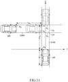
- FIG. 11 shows a positional relationship between the own vehicle 100 and the crossing target 200 at a certain time during the execution of the automatic brake control.
- the predicted travel region A100 of the own vehicle 100 and the predicted movement region A200 of the crossing target 200 are orthogonal to each other.
- the intersecting region CA is a quadrangle.
- the crossing target 200 is moving such that the crossing target 200 enters the intersecting region CA from the left side of the own vehicle 100.
- the crossing target 200 enters the intersecting region CA from an edge H L which is out of four edges surrounding the intersecting region CA and exists on the left side, passes through the intersecting region CA, and exits from an edge H R on the right side.
- the own vehicle 100 enters the intersecting region CA from an edge H D which is out of the four edges surrounding the intersecting region CA and exists on the lower side, passes through the intersecting region CA, and exits from an edge H U on the upper side.
- Od in is a distance between a position Pe of the front end (left front end) of the own vehicle 100 at the current time and the collision avoidance point P, and B is an overall length of the own vehicle 100.
- a distance traveled by the crossing target 200 from the current position of FIG. 11 to reach the intersecting region CA is represented by Td in
- a speed (current speed) of the crossing target 200 at the current time is represented by V p
- the distance Td in is a distance from a position Pp of a front end (left front end) of the crossing target 200 at the current time and the collision avoidance point P.
- the distance L 2 is calculated such that each "t” of Equation (3) is changed by a minute time, to thereby obtain “t” at which the distance L 2 is equal to the distance Td in .
- the value "t” obtained in this manner is the crossing target reaching predicted time T 2 .
- the CPU 11 calculates the predicted movement region of the detected moving target. After that, the CPU 11 determines whether or not the calculated predicted movement region of the moving target intersects with the predicted travel region A100 of the own vehicle 100 (S103). For example, the CPU 11 can determine whether or not the predicted movement region of the moving target intersects with the predicted travel region A100 of the own vehicle 100 based on whether or not the intersecting region of the predicted movement region of the moving target and the predicted travel region A100 of the own vehicle 100 is formed on the X-Y coordinate plane of FIG. 5 .
- the CPU 11 sets the detected moving target as the crossing target 200. After that, the CPU 11 determines the type of the crossing target 200 (S105). In this case, the CPU 11 can determine the type of the crossing target 200 based on the information acquired from the front camera sensor 262a. For example, the CPU 11 determines whether the crossing target 200 is a vehicle, a two-wheeled vehicle, a bicycle, or a pedestrian in S105.
- the CPU 11 executes collision possibility determination processing (S106).
- the CPU 11 calculates positions at which the own vehicle 100 and the crossing target 200 probably exist each time the minute time elapses from the current time when the own vehicle 100 and the crossing target 200 maintain the current speeds and accelerations.
- the CPU 11 compares a relationship between the calculated position at which the own vehicle 100 probably exists and the calculated position at which the crossing target 200 probably exists each time the minute time elapses, to thereby determine whether or not the prediction that the own vehicle 100 and the crossing target 200 collide with each other is correct.
- the CPU 11 determines whether or not the prediction of the collision between the own vehicle 100 and the crossing target 200 is determined as correct, that is, whether or not the collision possibility exists (S107).
- the CPU 11 temporarily finishes this program.
- the processing proceeds to S108.
- the CPU 11 determines whether or not the time TTC until the own vehicle 100 and the crossing target 200 collide with each other is equal to or shorter than the predetermined threshold time TTCth set in advance. When the time TTC is longer than the threshold time TTCth (No in S108), the CPU 11 temporarily finishes this program. When the time TTC is equal to or shorter than the threshold time TTCth (Yes in S108), the CPU 11 determines that the probability of the collision between the own vehicle 100 and the crossing target 200 is high. Thus, the processing proceeds to S109.
- the CPU 11 starts the automatic brake control. After that, the CPU 11 calculates a requested deceleration ⁇ Dreq (S110).
- the requested deceleration ⁇ Dreq may be a fixed value or a variable value. After that, the processing proceeds to S111.
- the CPU 11 outputs, to the braking ECU 41, a deceleration command signal for controlling the braking actuator 42 so that the deceleration of the own vehicle 100 matches the requested deceleration ⁇ Dreq.
- the braking ECU 41 controls the braking actuator 42 so that the deceleration matches the requested deceleration ⁇ Dreq.
- the own vehicle 100 decelerates.
- the CPU 11 determines whether or not a control finish flag F is set to 1.
- the control finish flag F is set to 1 when the control finish condition for the automatic brake control is satisfied, and is set to 0 when the control finish condition is not satisfied.
- the CPU 11 determines that the control finish flag F is not set to 1 in S112, that is, the control finish flag F is set to 0 (No in S112), the CPU 11 determines that the control finish condition for the automatic brake control is not satisfied.
- the processing returns to S110. In this case, the CPU 11 again calculates the requested deceleration ⁇ Dreq (S110), and outputs the deceleration command signal (S111). As a result, the automatic brake control is continued.
- FIG. 13 is a flowchart for illustrating an example of a control finish condition determination program executed by the CPU 11 of the vehicle control ECU 10 to set the control finish flag F.
- This program is executed when the automatic brake control is started in S109 of FIG. 12A .
- the CPU 11 first determines whether or not the position of the crossing target 200 exists in the intersecting region CA in S201 of FIG. 13 . In this case, the CPU 11 can determine whether or not the position of the crossing target 200 exists in the intersecting region CA based on the relationship between the position of the crossing target 200 and the position of the intersecting region CA.
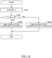
- FIG. 14 is a flowchart for illustrating an example of an own vehicle stop condition determination program executed by the CPU 11 of the vehicle control ECU 10 to determine whether or not the own vehicle stop condition is satisfied.
- the CPU 11 acquires the own vehicle speed V e in S301 of FIG. 14 .
- the CPU 11 determines whether or not the own vehicle speed V e is 0 km/H, that is, the own vehicle 100 is stopped (S302).
- the processing proceeds to S304.
- the own vehicle speed V e is 0 km/H (Yes in S302)
- the processing proceeds to S303.
- the CPU 11 determines that the own vehicle stop condition is satisfied. After that, the CPU 11 finishes this program. Moreover, in S304, the CPU 11 determines that the own vehicle stop condition is not satisfied. After that, the CPU 11 finishes this program.
- FIG. 15 is a flowchart for illustrating an example of a crossing target passage condition determination program executed by the CPU 11 of the vehicle control ECU 10 to determine whether or not the crossing target passage condition is satisfied.
- the CPU 11 estimates a movement direction D of the crossing target 200 in S401 of FIG. 15 .
- the CPU 11 obtains the speed vector of the crossing target 200 based on the relative distance and the relative speed between the crossing target 200 and the own vehicle 100 and the orientation in which the crossing target 200 exists.
- the CPU 11 can estimate the movement direction D of the crossing target 200 from the obtained direction of the speed vector of the crossing target 200.
- the CPU 11 determines that the crossing target 200 has not yet passed beyond the intersecting region CA. In this case, the processing proceeds to S404. In S404, the CPU 11 determines that the crossing target passage condition is not satisfied. After that, the CPU 11 finishes this program.
- FIG. 16 is a flowchart for illustrating an example of a crossing target stop condition determination program executed by the CPU 11 of the vehicle control ECU 10 to determine whether or not the crossing target stop condition is satisfied.
- the CPU 11 calculates the speed V p of the crossing target 200 in S501 of FIG. 16 . After that, the CPU 11 determines whether or not the speed V p of the crossing target 200 is 0 km/H, that is, the crossing target 200 is stopped (S502). When the speed V p of the crossing target 200 is not 0 km/H (No in S502), the processing proceeds to S504. In S504, the CPU 11 determines that the crossing target stop condition is not satisfied. After that, the CPU 11 finishes this program. Meanwhile, when the speed V p of the crossing target 200 is 0 km/H (Yes in S502), the processing proceeds to S503. In S503, the CPU 11 determines that the crossing target stop condition is satisfied. After that, the CPU 11 finishes this program.
- the CPU 11 executes the crossing target stop condition determination program described above, to thereby determine that the crossing target stop condition is satisfied when the crossing target 200 is stopped and determine that the crossing target stop condition is not satisfied when the crossing target 200 is moving.
- the case in which the CPU 11 executes the crossing target stop condition determination program of FIG. 16 is a case in which the position of the crossing target 200 does not exist in the intersecting region CA and the crossing target passage condition is not satisfied, that is, the crossing target 200 has not passed beyond the intersecting region CA.
- the case in which it is determined, through the execution of this program, that the crossing target stop condition is satisfied is the case in which the crossing target 200 is stopped before reaching the intersecting region CA.
- the case in which it is determined, through execution of this program, that the crossing target stop condition is not satisfied is the case in which the crossing target 200 is moving at a position before reaching the intersecting region CA.
- the processing proceeds to S206.
- S206 the CPU 11 determines whether or not the collision between the own vehicle 100 and the crossing target 200 is avoidable based on a result of the collision avoidance determination processing. When the collision is unavoidable (No in S206), the processing proceeds to S209. In S209, the CPU 11 determines that the control finish condition is not satisfied, and sets the control finish flag F to 0. After that, the CPU 11 finishes this program.
- the processing proceeds to S207.
- the CPU 11 determines whether or not the collision avoidance mode is the avoidance mode 2. That is, the CPU 11 determines, through the collision avoidance determination processing, whether or not it is predicted that the collision is avoided by the crossing target 200 reaching the intersecting region CA after the own vehicle 100 has passed beyond the intersecting region CA as illustrated in FIG. 10 .
- the collision avoidance mode is not the avoidance mode 2, that is, the collision avoidance mode is the avoidance mode 1 of FIG. 9 (No in 207)
- the CPU 11 determines that the control finish condition is not satisfied.
- the CPU 11 sets the control finish flag F to 0 (S209). After that, the CPU 11 finishes this program.
- FIG. 17 is a flowchart for illustrating an example of an avoidance condition determination program executed by the CPU 11 of the vehicle control ECU 10 to determine whether or not the avoidance condition is satisfied.
- the CPU 11 calculates the distance Od in in S601 of FIG. 17 .
- the CPU 11 can calculate, as the distance Od in , the distance in the X-axis direction between the position Pe of the left front end of the own vehicle 100 existing at the current position and the collision avoidance point P.
- the CPU 11 calculates the distance Td in (S602). For example, when the own vehicle 100 and the crossing target 200 move as illustrated in FIG. 11 , the CPU 11 can calculate, as the distance Td in , the distance in the Y-axis direction between the position Pp of the left front end of the crossing target 200 existing at the current position and the collision avoidance point P.
- the CPU 11 acquires the own vehicle speed V e at the current time (S603), and further acquires the speed V p of the crossing target 200 at the current time (S604).
- the CPU 11 calculates the own vehicle passage predicted time T 1 (S605).
- the own vehicle passage predicted time T 1 is the time taken to pass beyond the intersecting region CA (specifically, the collision avoidance point P of the intersecting region CA) from the current position when it is assumed that the own vehicle 100 maintains the current speed (speed V e ) (that is, the automatic brake control is finished at the current time).
- the own vehicle passage predicted time T 1 can be calculated as given by Equation (2).
- Equation (2) the overall length B of the own vehicle 100 is stored in advance.
- the CPU 11 reads out the acceleration ⁇ p and the acceleration gradient ⁇ p corresponding to the type of the crossing target 200 from the ROM 12, and uses the read-out acceleration ⁇ p and acceleration gradient ⁇ p to calculate the crossing target reaching predicted time T 2 .
- the CPU 11 determines whether or not the own vehicle passage predicted time T 1 is shorter than the crossing target reaching predicted time T 2 (S607).
- the CPU 11 determines that the own vehicle 100 first passes beyond the intersecting region CA, and the crossing target 200 traveling while accelerating at the predetermined acceleration ⁇ p and acceleration gradient ⁇ p then reaches the intersecting region CA even when the automatic brake control is finished at the current time. In this case, the CPU 11 determines that the avoidance condition is satisfied (S608). After that, the CPU 11 finishes this program.
- the CPU 11 determines that the crossing target 200 traveling while accelerating at the predetermined acceleration ⁇ p and acceleration gradient ⁇ p enters the intersecting region CA before the own vehicle 100 passes beyond the intersecting region CA when the automatic brake control is finished at the current time. In this case, the CPU 11 determines that there is a possibility of a collision between the own vehicle 100 and the crossing target 200 with each other in the intersecting region CA when the automatic brake control is finished at the current time, and hence determines that the avoidance condition is not satisfied (S609). After that, the CPU 11 finishes this program.
- the CPU 11 executes the avoidance condition determination program described above, to thereby determine that the avoidance condition is satisfied when the own vehicle passage predicted time T 1 is shorter than the crossing target reaching predicted time T 2 and determine that the avoidance condition is not satisfied when the own vehicle passage predicted time T 1 is equal to or longer than the crossing target reaching predicted time T 2 .
- the CPU 11 determines that the avoidance condition is satisfied in S208 of FIG. 13 (Yes in S208), the CPU 11 determines that the control finish condition is satisfied as a result of the avoidance condition being satisfied. Thus, in S210, the CPU 11 sets the control finish flag F to 1. After that, the CPU 11 finishes this program. Meanwhile, when the CPU 11 determines that the avoidance condition is not satisfied in S208 (No in S208), the CPU 11 determines that the control finish condition is not satisfied. Thus, the CPU 11 sets the control finish flag F to 0 (S209). After that, the CPU 11 finishes this program.
- the automatic brake control is finished. Moreover, when the own vehicle stop condition is not satisfied, the crossing target passage condition is not satisfied, and the crossing target stop condition is not satisfied, it is determined whether or not the avoidance condition is satisfied. After that, when the avoidance condition is satisfied, the automatic brake control is finished.
- the vehicle control device according to the at least one embodiment of the present disclosure can be configured as described in the following modification examples.
- the crossing target reaching predicted time used to determine whether or not the avoidance condition is satisfied may be a time taken by the crossing target to reach the intersecting region CA from the current position when it is assumed that the crossing target maintains the current speed.
- the vehicle control ECU 10 may calculate, as the crossing target reaching predicted time, the time taken by the crossing target to reach the intersecting region CA from the current position when it is assumed that the crossing target maintains the current speed (that is, the acceleration and the acceleration gradient are 0).
- the crossing target reaching predicted time may be a time taken by the crossing target to reach the intersecting region CA from the current position when it is assumed that the crossing target accelerates at a predetermined acceleration from the current speed. That is, the crossing target reaching predicted time may be calculated without setting the acceleration gradient for the crossing target.
Landscapes
- Engineering & Computer Science (AREA)
- Transportation (AREA)
- Mechanical Engineering (AREA)
- Automation & Control Theory (AREA)
- Physics & Mathematics (AREA)
- General Physics & Mathematics (AREA)
- Human Computer Interaction (AREA)
- Traffic Control Systems (AREA)
- Regulating Braking Force (AREA)
- Control Of Driving Devices And Active Controlling Of Vehicle (AREA)
Applications Claiming Priority (1)
| Application Number | Priority Date | Filing Date | Title |
|---|---|---|---|
| JP2023213258A JP2025097140A (ja) | 2023-12-18 | 2023-12-18 | 車両制御装置 |
Publications (1)
| Publication Number | Publication Date |
|---|---|
| EP4574604A1 true EP4574604A1 (de) | 2025-06-25 |
Family
ID=93648469
Family Applications (1)
| Application Number | Title | Priority Date | Filing Date |
|---|---|---|---|
| EP24214909.4A Pending EP4574604A1 (de) | 2023-12-18 | 2024-11-22 | Fahrzeugsteuerungsvorrichtung |
Country Status (5)
| Country | Link |
|---|---|
| US (1) | US20250196821A1 (de) |
| EP (1) | EP4574604A1 (de) |
| JP (1) | JP2025097140A (de) |
| KR (1) | KR20250094586A (de) |
| CN (1) | CN120171520A (de) |
Citations (4)
| Publication number | Priority date | Publication date | Assignee | Title |
|---|---|---|---|---|
| DE102014006486A1 (de) * | 2013-05-03 | 2014-11-06 | Mando Corporation | Verfahren zum verhindern einer fahrzeugkollision |
| JP2018111335A (ja) | 2017-01-06 | 2018-07-19 | トヨタ自動車株式会社 | 衝突回避装置 |
| US20220281482A1 (en) * | 2021-03-03 | 2022-09-08 | Honda Motor Co., Ltd. | Vehicle control device, vehicle control method, and computer-readable storage medium storing program |
| CN116714589A (zh) * | 2023-06-21 | 2023-09-08 | 吉林大学 | 一种拟人化的左转交叉路口决策方法 |
-
2023
- 2023-12-18 JP JP2023213258A patent/JP2025097140A/ja active Pending
-
2024
- 2024-11-21 US US18/955,175 patent/US20250196821A1/en active Pending
- 2024-11-22 EP EP24214909.4A patent/EP4574604A1/de active Pending
- 2024-12-17 KR KR1020240188138A patent/KR20250094586A/ko active Pending
- 2024-12-17 CN CN202411860076.1A patent/CN120171520A/zh active Pending
Patent Citations (4)
| Publication number | Priority date | Publication date | Assignee | Title |
|---|---|---|---|---|
| DE102014006486A1 (de) * | 2013-05-03 | 2014-11-06 | Mando Corporation | Verfahren zum verhindern einer fahrzeugkollision |
| JP2018111335A (ja) | 2017-01-06 | 2018-07-19 | トヨタ自動車株式会社 | 衝突回避装置 |
| US20220281482A1 (en) * | 2021-03-03 | 2022-09-08 | Honda Motor Co., Ltd. | Vehicle control device, vehicle control method, and computer-readable storage medium storing program |
| CN116714589A (zh) * | 2023-06-21 | 2023-09-08 | 吉林大学 | 一种拟人化的左转交叉路口决策方法 |
Also Published As
| Publication number | Publication date |
|---|---|
| CN120171520A (zh) | 2025-06-20 |
| US20250196821A1 (en) | 2025-06-19 |
| KR20250094586A (ko) | 2025-06-25 |
| JP2025097140A (ja) | 2025-06-30 |
Similar Documents
| Publication | Publication Date | Title |
|---|---|---|
| JP4762610B2 (ja) | 車両の走行安全装置 | |
| US11370432B2 (en) | Vehicle control apparatus | |
| US11731619B2 (en) | Collision avoidance assist apparatus | |
| CN114701496B (zh) | 车辆驾驶支援装置 | |
| US20180126965A1 (en) | Vehicle control device, vehicle control method, and vehicle control program | |
| CN111149142A (zh) | 控制对象车辆设定装置、控制对象车辆设定系统及控制对象车辆设定方法 | |
| US20210114591A1 (en) | Driving assistance control apparatus for vehicle, driving assistance control system for vehicle, and driving assistance control method for vehicle | |
| JP2022024322A (ja) | 衝突回避支援装置 | |
| US20210370924A1 (en) | Driving assistance apparatus | |
| JP2008296887A (ja) | 車両制御装置 | |
| CN115175837B (zh) | 停车辅助装置以及停车辅助方法 | |
| JP2012224316A (ja) | 走行制御装置 | |
| US11072325B2 (en) | Drive assist device, drive assist method and non-transitory computer readable storage medium for storing programs thereof | |
| CN113942501B (zh) | 车辆控制装置 | |
| US20210300469A1 (en) | Travel control system | |
| JP7268464B2 (ja) | 車両制御装置 | |
| US20250196821A1 (en) | Vehicle control device | |
| US20230123788A1 (en) | Vehicle traveling control device and vehicle traveling control method | |
| JP7690891B2 (ja) | 追越し制御方法 | |
| KR102950101B1 (ko) | 운전 지원 장치, 운전 지원 방법 및 기억 매체 | |
| US12252117B2 (en) | Vehicle driving assistance apparatus, vehicle driving assistance method, and computer-readable storage medium storing vehicle driving assistance program | |
| US20250196848A1 (en) | Driving assistance device, driving assistance method, and program | |
| US12600352B2 (en) | Vehicle driving support device | |
| US20250136111A1 (en) | Travel control device | |
| US20240140411A1 (en) | Vehicle control apparatus |
Legal Events
| Date | Code | Title | Description |
|---|---|---|---|
| PUAI | Public reference made under article 153(3) epc to a published international application that has entered the european phase |
Free format text: ORIGINAL CODE: 0009012 |
|
| STAA | Information on the status of an ep patent application or granted ep patent |
Free format text: STATUS: REQUEST FOR EXAMINATION WAS MADE |
|
| 17P | Request for examination filed |
Effective date: 20241122 |
|
| AK | Designated contracting states |
Kind code of ref document: A1 Designated state(s): AL AT BE BG CH CY CZ DE DK EE ES FI FR GB GR HR HU IE IS IT LI LT LU LV MC ME MK MT NL NO PL PT RO RS SE SI SK SM TR |