EP4574609A1 - Dispositif d'aide à la conduite, procédé d'aide à la conduite et programme d'aide à la conduite - Google Patents
Dispositif d'aide à la conduite, procédé d'aide à la conduite et programme d'aide à la conduite Download PDFInfo
- Publication number
- EP4574609A1 EP4574609A1 EP24221244.7A EP24221244A EP4574609A1 EP 4574609 A1 EP4574609 A1 EP 4574609A1 EP 24221244 A EP24221244 A EP 24221244A EP 4574609 A1 EP4574609 A1 EP 4574609A1
- Authority
- EP
- European Patent Office
- Prior art keywords
- vehicle
- preceding vehicle
- lane
- turn
- general road
- Prior art date
- Legal status (The legal status is an assumption and is not a legal conclusion. Google has not performed a legal analysis and makes no representation as to the accuracy of the status listed.)
- Pending
Links
Images


Classifications
-
- B—PERFORMING OPERATIONS; TRANSPORTING
- B60—VEHICLES IN GENERAL
- B60W—CONJOINT CONTROL OF VEHICLE SUB-UNITS OF DIFFERENT TYPE OR DIFFERENT FUNCTION; CONTROL SYSTEMS SPECIALLY ADAPTED FOR HYBRID VEHICLES; ROAD VEHICLE DRIVE CONTROL SYSTEMS FOR PURPOSES NOT RELATED TO THE CONTROL OF A PARTICULAR SUB-UNIT
- B60W30/00—Purposes of road vehicle drive control systems not related to the control of a particular sub-unit, e.g. of systems using conjoint control of vehicle sub-units
- B60W30/14—Adaptive cruise control
- B60W30/143—Speed control
- B60W30/146—Speed limiting
-
- B—PERFORMING OPERATIONS; TRANSPORTING
- B60—VEHICLES IN GENERAL
- B60W—CONJOINT CONTROL OF VEHICLE SUB-UNITS OF DIFFERENT TYPE OR DIFFERENT FUNCTION; CONTROL SYSTEMS SPECIALLY ADAPTED FOR HYBRID VEHICLES; ROAD VEHICLE DRIVE CONTROL SYSTEMS FOR PURPOSES NOT RELATED TO THE CONTROL OF A PARTICULAR SUB-UNIT
- B60W30/00—Purposes of road vehicle drive control systems not related to the control of a particular sub-unit, e.g. of systems using conjoint control of vehicle sub-units
- B60W30/08—Active safety systems predicting or avoiding probable or impending collision or attempting to minimise its consequences
- B60W30/09—Taking automatic action to avoid collision, e.g. braking and steering
-
- G—PHYSICS
- G08—SIGNALLING
- G08G—TRAFFIC CONTROL SYSTEMS
- G08G1/00—Traffic control systems for road vehicles
- G08G1/09—Arrangements for giving variable traffic instructions
- G08G1/0962—Arrangements for giving variable traffic instructions having an indicator mounted inside the vehicle, e.g. giving voice messages
- G08G1/0967—Systems involving transmission of highway information, e.g. weather, speed limits
- G08G1/096708—Systems involving transmission of highway information, e.g. weather, speed limits where the received information might be used to generate an automatic action on the vehicle control
- G08G1/096725—Systems involving transmission of highway information, e.g. weather, speed limits where the received information might be used to generate an automatic action on the vehicle control where the received information generates an automatic action on the vehicle control
-
- B—PERFORMING OPERATIONS; TRANSPORTING
- B60—VEHICLES IN GENERAL
- B60Q—ARRANGEMENT OF SIGNALLING OR LIGHTING DEVICES, THE MOUNTING OR SUPPORTING THEREOF OR CIRCUITS THEREFOR, FOR VEHICLES IN GENERAL
- B60Q1/00—Arrangement of optical signalling or lighting devices, the mounting or supporting thereof or circuits therefor
- B60Q1/26—Arrangement of optical signalling or lighting devices, the mounting or supporting thereof or circuits therefor the devices being primarily intended to indicate the vehicle, or parts thereof, or to give signals, to other traffic
- B60Q1/34—Arrangement of optical signalling or lighting devices, the mounting or supporting thereof or circuits therefor the devices being primarily intended to indicate the vehicle, or parts thereof, or to give signals, to other traffic for indicating change of drive direction
-
- B—PERFORMING OPERATIONS; TRANSPORTING
- B60—VEHICLES IN GENERAL
- B60W—CONJOINT CONTROL OF VEHICLE SUB-UNITS OF DIFFERENT TYPE OR DIFFERENT FUNCTION; CONTROL SYSTEMS SPECIALLY ADAPTED FOR HYBRID VEHICLES; ROAD VEHICLE DRIVE CONTROL SYSTEMS FOR PURPOSES NOT RELATED TO THE CONTROL OF A PARTICULAR SUB-UNIT
- B60W10/00—Conjoint control of vehicle sub-units of different type or different function
- B60W10/18—Conjoint control of vehicle sub-units of different type or different function including control of braking systems
-
- B—PERFORMING OPERATIONS; TRANSPORTING
- B60—VEHICLES IN GENERAL
- B60W—CONJOINT CONTROL OF VEHICLE SUB-UNITS OF DIFFERENT TYPE OR DIFFERENT FUNCTION; CONTROL SYSTEMS SPECIALLY ADAPTED FOR HYBRID VEHICLES; ROAD VEHICLE DRIVE CONTROL SYSTEMS FOR PURPOSES NOT RELATED TO THE CONTROL OF A PARTICULAR SUB-UNIT
- B60W30/00—Purposes of road vehicle drive control systems not related to the control of a particular sub-unit, e.g. of systems using conjoint control of vehicle sub-units
- B60W30/14—Adaptive cruise control
- B60W30/143—Speed control
-
- B—PERFORMING OPERATIONS; TRANSPORTING
- B60—VEHICLES IN GENERAL
- B60W—CONJOINT CONTROL OF VEHICLE SUB-UNITS OF DIFFERENT TYPE OR DIFFERENT FUNCTION; CONTROL SYSTEMS SPECIALLY ADAPTED FOR HYBRID VEHICLES; ROAD VEHICLE DRIVE CONTROL SYSTEMS FOR PURPOSES NOT RELATED TO THE CONTROL OF A PARTICULAR SUB-UNIT
- B60W30/00—Purposes of road vehicle drive control systems not related to the control of a particular sub-unit, e.g. of systems using conjoint control of vehicle sub-units
- B60W30/14—Adaptive cruise control
- B60W30/16—Control of distance between vehicles, e.g. keeping a distance to preceding vehicle
- B60W30/162—Speed limiting therefor
-
- B—PERFORMING OPERATIONS; TRANSPORTING
- B60—VEHICLES IN GENERAL
- B60W—CONJOINT CONTROL OF VEHICLE SUB-UNITS OF DIFFERENT TYPE OR DIFFERENT FUNCTION; CONTROL SYSTEMS SPECIALLY ADAPTED FOR HYBRID VEHICLES; ROAD VEHICLE DRIVE CONTROL SYSTEMS FOR PURPOSES NOT RELATED TO THE CONTROL OF A PARTICULAR SUB-UNIT
- B60W30/00—Purposes of road vehicle drive control systems not related to the control of a particular sub-unit, e.g. of systems using conjoint control of vehicle sub-units
- B60W30/18—Propelling the vehicle
- B60W30/18009—Propelling the vehicle related to particular drive situations
- B60W30/18109—Braking
-
- B—PERFORMING OPERATIONS; TRANSPORTING
- B60—VEHICLES IN GENERAL
- B60W—CONJOINT CONTROL OF VEHICLE SUB-UNITS OF DIFFERENT TYPE OR DIFFERENT FUNCTION; CONTROL SYSTEMS SPECIALLY ADAPTED FOR HYBRID VEHICLES; ROAD VEHICLE DRIVE CONTROL SYSTEMS FOR PURPOSES NOT RELATED TO THE CONTROL OF A PARTICULAR SUB-UNIT
- B60W40/00—Estimation or calculation of non-directly measurable driving parameters for road vehicle drive control systems not related to the control of a particular sub unit, e.g. by using mathematical models
- B60W40/02—Estimation or calculation of non-directly measurable driving parameters for road vehicle drive control systems not related to the control of a particular sub unit, e.g. by using mathematical models related to ambient conditions
-
- G—PHYSICS
- G08—SIGNALLING
- G08G—TRAFFIC CONTROL SYSTEMS
- G08G1/00—Traffic control systems for road vehicles
- G08G1/01—Detecting movement of traffic to be counted or controlled
- G08G1/04—Detecting movement of traffic to be counted or controlled using optical or ultrasonic detectors
-
- G—PHYSICS
- G08—SIGNALLING
- G08G—TRAFFIC CONTROL SYSTEMS
- G08G1/00—Traffic control systems for road vehicles
- G08G1/01—Detecting movement of traffic to be counted or controlled
- G08G1/052—Detecting movement of traffic to be counted or controlled with provision for determining speed or overspeed
-
- G—PHYSICS
- G08—SIGNALLING
- G08G—TRAFFIC CONTROL SYSTEMS
- G08G1/00—Traffic control systems for road vehicles
- G08G1/09—Arrangements for giving variable traffic instructions
- G08G1/0962—Arrangements for giving variable traffic instructions having an indicator mounted inside the vehicle, e.g. giving voice messages
- G08G1/0967—Systems involving transmission of highway information, e.g. weather, speed limits
- G08G1/096766—Systems involving transmission of highway information, e.g. weather, speed limits where the system is characterised by the origin of the information transmission
- G08G1/096791—Systems involving transmission of highway information, e.g. weather, speed limits where the system is characterised by the origin of the information transmission where the origin of the information is another vehicle
-
- B—PERFORMING OPERATIONS; TRANSPORTING
- B60—VEHICLES IN GENERAL
- B60W—CONJOINT CONTROL OF VEHICLE SUB-UNITS OF DIFFERENT TYPE OR DIFFERENT FUNCTION; CONTROL SYSTEMS SPECIALLY ADAPTED FOR HYBRID VEHICLES; ROAD VEHICLE DRIVE CONTROL SYSTEMS FOR PURPOSES NOT RELATED TO THE CONTROL OF A PARTICULAR SUB-UNIT
- B60W2420/00—Indexing codes relating to the type of sensors based on the principle of their operation
- B60W2420/40—Photo, light or radio wave sensitive means, e.g. infrared sensors
- B60W2420/403—Image sensing, e.g. optical camera
-
- B—PERFORMING OPERATIONS; TRANSPORTING
- B60—VEHICLES IN GENERAL
- B60W—CONJOINT CONTROL OF VEHICLE SUB-UNITS OF DIFFERENT TYPE OR DIFFERENT FUNCTION; CONTROL SYSTEMS SPECIALLY ADAPTED FOR HYBRID VEHICLES; ROAD VEHICLE DRIVE CONTROL SYSTEMS FOR PURPOSES NOT RELATED TO THE CONTROL OF A PARTICULAR SUB-UNIT
- B60W2420/00—Indexing codes relating to the type of sensors based on the principle of their operation
- B60W2420/40—Photo, light or radio wave sensitive means, e.g. infrared sensors
- B60W2420/408—Radar; Laser, e.g. lidar
-
- B—PERFORMING OPERATIONS; TRANSPORTING
- B60—VEHICLES IN GENERAL
- B60W—CONJOINT CONTROL OF VEHICLE SUB-UNITS OF DIFFERENT TYPE OR DIFFERENT FUNCTION; CONTROL SYSTEMS SPECIALLY ADAPTED FOR HYBRID VEHICLES; ROAD VEHICLE DRIVE CONTROL SYSTEMS FOR PURPOSES NOT RELATED TO THE CONTROL OF A PARTICULAR SUB-UNIT
- B60W2520/00—Input parameters relating to overall vehicle dynamics
- B60W2520/10—Longitudinal speed
- B60W2520/105—Longitudinal acceleration
-
- B—PERFORMING OPERATIONS; TRANSPORTING
- B60—VEHICLES IN GENERAL
- B60W—CONJOINT CONTROL OF VEHICLE SUB-UNITS OF DIFFERENT TYPE OR DIFFERENT FUNCTION; CONTROL SYSTEMS SPECIALLY ADAPTED FOR HYBRID VEHICLES; ROAD VEHICLE DRIVE CONTROL SYSTEMS FOR PURPOSES NOT RELATED TO THE CONTROL OF A PARTICULAR SUB-UNIT
- B60W2552/00—Input parameters relating to infrastructure
- B60W2552/05—Type of road, e.g. motorways, local streets, paved or unpaved roads
-
- B—PERFORMING OPERATIONS; TRANSPORTING
- B60—VEHICLES IN GENERAL
- B60W—CONJOINT CONTROL OF VEHICLE SUB-UNITS OF DIFFERENT TYPE OR DIFFERENT FUNCTION; CONTROL SYSTEMS SPECIALLY ADAPTED FOR HYBRID VEHICLES; ROAD VEHICLE DRIVE CONTROL SYSTEMS FOR PURPOSES NOT RELATED TO THE CONTROL OF A PARTICULAR SUB-UNIT
- B60W2552/00—Input parameters relating to infrastructure
- B60W2552/10—Number of lanes
-
- B—PERFORMING OPERATIONS; TRANSPORTING
- B60—VEHICLES IN GENERAL
- B60W—CONJOINT CONTROL OF VEHICLE SUB-UNITS OF DIFFERENT TYPE OR DIFFERENT FUNCTION; CONTROL SYSTEMS SPECIALLY ADAPTED FOR HYBRID VEHICLES; ROAD VEHICLE DRIVE CONTROL SYSTEMS FOR PURPOSES NOT RELATED TO THE CONTROL OF A PARTICULAR SUB-UNIT
- B60W2552/00—Input parameters relating to infrastructure
- B60W2552/53—Road markings, e.g. lane marker or crosswalk
-
- B—PERFORMING OPERATIONS; TRANSPORTING
- B60—VEHICLES IN GENERAL
- B60W—CONJOINT CONTROL OF VEHICLE SUB-UNITS OF DIFFERENT TYPE OR DIFFERENT FUNCTION; CONTROL SYSTEMS SPECIALLY ADAPTED FOR HYBRID VEHICLES; ROAD VEHICLE DRIVE CONTROL SYSTEMS FOR PURPOSES NOT RELATED TO THE CONTROL OF A PARTICULAR SUB-UNIT
- B60W2554/00—Input parameters relating to objects
- B60W2554/40—Dynamic objects, e.g. animals, windblown objects
- B60W2554/404—Characteristics
- B60W2554/4041—Position
-
- B—PERFORMING OPERATIONS; TRANSPORTING
- B60—VEHICLES IN GENERAL
- B60W—CONJOINT CONTROL OF VEHICLE SUB-UNITS OF DIFFERENT TYPE OR DIFFERENT FUNCTION; CONTROL SYSTEMS SPECIALLY ADAPTED FOR HYBRID VEHICLES; ROAD VEHICLE DRIVE CONTROL SYSTEMS FOR PURPOSES NOT RELATED TO THE CONTROL OF A PARTICULAR SUB-UNIT
- B60W2554/00—Input parameters relating to objects
- B60W2554/40—Dynamic objects, e.g. animals, windblown objects
- B60W2554/404—Characteristics
- B60W2554/4042—Longitudinal speed
-
- B—PERFORMING OPERATIONS; TRANSPORTING
- B60—VEHICLES IN GENERAL
- B60W—CONJOINT CONTROL OF VEHICLE SUB-UNITS OF DIFFERENT TYPE OR DIFFERENT FUNCTION; CONTROL SYSTEMS SPECIALLY ADAPTED FOR HYBRID VEHICLES; ROAD VEHICLE DRIVE CONTROL SYSTEMS FOR PURPOSES NOT RELATED TO THE CONTROL OF A PARTICULAR SUB-UNIT
- B60W2554/00—Input parameters relating to objects
- B60W2554/40—Dynamic objects, e.g. animals, windblown objects
- B60W2554/404—Characteristics
- B60W2554/4045—Intention, e.g. lane change or imminent movement
-
- B—PERFORMING OPERATIONS; TRANSPORTING
- B60—VEHICLES IN GENERAL
- B60W—CONJOINT CONTROL OF VEHICLE SUB-UNITS OF DIFFERENT TYPE OR DIFFERENT FUNCTION; CONTROL SYSTEMS SPECIALLY ADAPTED FOR HYBRID VEHICLES; ROAD VEHICLE DRIVE CONTROL SYSTEMS FOR PURPOSES NOT RELATED TO THE CONTROL OF A PARTICULAR SUB-UNIT
- B60W2554/00—Input parameters relating to objects
- B60W2554/80—Spatial relation or speed relative to objects
- B60W2554/802—Longitudinal distance
-
- B—PERFORMING OPERATIONS; TRANSPORTING
- B60—VEHICLES IN GENERAL
- B60W—CONJOINT CONTROL OF VEHICLE SUB-UNITS OF DIFFERENT TYPE OR DIFFERENT FUNCTION; CONTROL SYSTEMS SPECIALLY ADAPTED FOR HYBRID VEHICLES; ROAD VEHICLE DRIVE CONTROL SYSTEMS FOR PURPOSES NOT RELATED TO THE CONTROL OF A PARTICULAR SUB-UNIT
- B60W2554/00—Input parameters relating to objects
- B60W2554/80—Spatial relation or speed relative to objects
- B60W2554/804—Relative longitudinal speed
-
- B—PERFORMING OPERATIONS; TRANSPORTING
- B60—VEHICLES IN GENERAL
- B60W—CONJOINT CONTROL OF VEHICLE SUB-UNITS OF DIFFERENT TYPE OR DIFFERENT FUNCTION; CONTROL SYSTEMS SPECIALLY ADAPTED FOR HYBRID VEHICLES; ROAD VEHICLE DRIVE CONTROL SYSTEMS FOR PURPOSES NOT RELATED TO THE CONTROL OF A PARTICULAR SUB-UNIT
- B60W2555/00—Input parameters relating to exterior conditions, not covered by groups B60W2552/00, B60W2554/00
- B60W2555/60—Traffic rules, e.g. speed limits or right of way
-
- B—PERFORMING OPERATIONS; TRANSPORTING
- B60—VEHICLES IN GENERAL
- B60W—CONJOINT CONTROL OF VEHICLE SUB-UNITS OF DIFFERENT TYPE OR DIFFERENT FUNCTION; CONTROL SYSTEMS SPECIALLY ADAPTED FOR HYBRID VEHICLES; ROAD VEHICLE DRIVE CONTROL SYSTEMS FOR PURPOSES NOT RELATED TO THE CONTROL OF A PARTICULAR SUB-UNIT
- B60W2556/00—Input parameters relating to data
- B60W2556/45—External transmission of data to or from the vehicle
- B60W2556/50—External transmission of data to or from the vehicle of positioning data, e.g. GPS [Global Positioning System] data
-
- B—PERFORMING OPERATIONS; TRANSPORTING
- B60—VEHICLES IN GENERAL
- B60W—CONJOINT CONTROL OF VEHICLE SUB-UNITS OF DIFFERENT TYPE OR DIFFERENT FUNCTION; CONTROL SYSTEMS SPECIALLY ADAPTED FOR HYBRID VEHICLES; ROAD VEHICLE DRIVE CONTROL SYSTEMS FOR PURPOSES NOT RELATED TO THE CONTROL OF A PARTICULAR SUB-UNIT
- B60W2720/00—Output or target parameters relating to overall vehicle dynamics
- B60W2720/10—Longitudinal speed
- B60W2720/106—Longitudinal acceleration
Definitions
- a preceding vehicle makes a left (right) turn
- the preceding vehicle is driving at a constant speed with its turn signal indicating a left (right) turn
- the conventional device does not perform automatic braking.
- the conventional device performs automatic braking when it detects that the preceding vehicle has started to decelerate.
- the timing for starting automatic braking is relatively late.
- the driver and passengers (occupants) of the own vehicle recognize that the turn signal of the preceding vehicle is activated, the occupants are likely to anticipate that the preceding vehicle will decelerate later. In such a situation, there is a possibility that the occupants may feel anxious if the own vehicle continues to travel without decelerating. Additionally, during this period, the distance between the own vehicle and the preceding vehicle may decrease, leading to a potential situation where the own vehicle and the preceding vehicle are in close proximity. In this case, the occupants of the own vehicle may feel anxious.
- One of the objectives of the present invention is to provide a driving assistance device that can improve the comfort of the occupants of the own vehicle in situations where the preceding vehicle is making a left or right turn.
- the driving assistance device of the present invention comprises:
- the processor is configured to:
- the driving assistance program according to the present invention causes a computer provided in the own vehicle to execute:
- the speed adjustment step includes:
- the processor executes the mild deceleration process or the acceleration suppression process in the first and second specific scenes. If the processor executes the mild deceleration process, the distance between the own vehicle and the preceding vehicle increases. If the processor executes the acceleration suppression process, the reduction in the distance between the own vehicle and the preceding vehicle is suppressed. In other words, according to the present invention, the distance between the own vehicle and the preceding vehicle can be relatively well maintained in these specific scenes. As a result, the likelihood of causing anxiety for the occupants is reduced.
- the present invention can improve the comfort of the own vehicle's occupants.
- the processor terminates the execution of the mild deceleration process or the acceleration suppression process at a second point in time when a predetermined time has elapsed from a first point in time when the execution of the mild deceleration process or the acceleration suppression process began in the first specific scene and the second specific scene.
- the distance between the own vehicle and the preceding vehicle may become excessively large.
- the upper limit of the time for executing the mild deceleration process or the acceleration suppression process is specified, the excessive increase in the distance between the own vehicle and the preceding vehicle is prevented.
- the processor executes a following process in scenes other than the first specific scene and the second specific scene, as the speed adjustment process, to adjust the speed of the own vehicle so that the distance between the own vehicle and the preceding vehicle matches a target value determined based on the speeds of the own vehicle and the preceding vehicle.
- the processor controls the drive device and/or the braking device to decelerate the own vehicle. That is, the own vehicle is automatically braked.
- the own vehicle can be decelerated with ample margin in such automatic braking. In other words, the deceleration (backward acceleration) of the own vehicle is small. This helps prevent the comfort of the occupants in the own vehicle from being compromised.
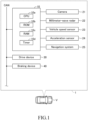
- the driving assistance device 1 As shown in FIG. 1 , the driving assistance device 1 according to one embodiment of the present invention is applied to a vehicle V (hereinafter referred to as the "own vehicle") equipped with an autonomous driving function.
- the driving assistance device 1 has a speed adjustment function that supports the driver's operation in adjusting the speed of the own vehicle when the autonomous driving function is disabled.
- the driving assistance device 1 comprises an ECU 10, an in-vehicle sensor 20, a drive device 30, and a braking device 40.
- the ECU 10 includes a microcomputer equipped with a CPU 10a, ROM 10b (rewritable non-volatile memory), RAM 10c, and a timer 10d.
- the CPU executes various functions by running programs (instructions) stored in the ROM.
- the ECU 10 is connected to other ECUs via a Controller Area Network (CAN).
- CAN Controller Area Network
- the in-vehicle sensor 20 includes a camera 21 and a millimeter-wave radar 22, both of which are used to acquire information about the preceding vehicle V1 located ahead of the own vehicle.
- the camera 21 includes an imaging device and an image analysis device.
- the imaging device is, for example, equipped with a built-in CCD. It is installed at the front of the own vehicle and oriented towards the front of the vehicle.
- the imaging device captures the area in front of the own vehicle at a predetermined frame rate to obtain image data.
- the image analysis device acquires the image data from the imaging device and analyzes it to recognize objects (targets) present within the field of view.
- the image analysis device recognizes, for example, lane markings (lane boundaries), road signs (such as those indicating left-turn or right-turn lanes), and identifies the preceding vehicle V1 positioned directly ahead of the own vehicle in its lane.
- the image analysis device recognizes the operating state of the turn signal (turn indicator) of the preceding vehicle V1, such as whether the turn signal is on.
- the recognition results are provided to the ECU 10.
- the millimeter-wave radar 22 includes a transmission/reception unit and a signal processing unit.
- the transmission/reception unit emits millimeter-wave band radio waves (hereinafter referred to as "millimeter waves") into the surrounding area in front of the own vehicle and receives reflected millimeter waves (echo waves) from objects in the area.
- the signal processing unit acquires various information about the reflection points of the millimeter waves based on physical quantities such as the time it takes for the echo wave to return, the attenuation level of the echo wave, and the frequency difference between the emitted and received millimeter waves. For example, the signal processing unit calculates the position (relative direction and distance) of each reflection point relative to the transmission/reception unit. It also calculates the velocity (relative speed) of each reflection point relative to the own vehicle. The results of these calculations (data showing the distribution of reflection points, such as their positions and velocities relative to the own vehicle) are provided to the ECU 10.
- the field of view of the camera 21 overlaps with the field of view of the millimeter-wave radar 22 (the area where millimeter waves are emitted).
- the ECU 10 can acquire information about objects ahead of the own vehicle, including the position (relative position) and speed (relative velocity) of objects relative to the own vehicle, based on fusion information that integrates data obtained from the camera 21 and the millimeter-wave radar 22.
- the in-vehicle sensor 20 also includes a vehicle speed sensor 23 and an acceleration sensor 24, which are used to acquire information about the behavior of the own vehicle.
- the vehicle speed sensor 23 includes a rotational speed measurement circuit and a speed calculation device.
- the rotational speed measurement circuit comprises a pulse generation circuit that outputs pulses (electrical signals) every time the vehicle's wheels rotate by a certain angle and a counter circuit that counts the number of pulses.
- the speed calculation device acquires the output value of the counter circuit (pulse count) at predetermined intervals (e.g., every unit time) and resets the count value to zero. In this way, the speed calculation device obtains the rotational speed N of the wheels per unit time. By multiplying the rotational speed N by a coefficient k, the speed calculation device obtains the speed vs (the absolute value of the forward speed) of the own vehicle.
- the speed calculation device provides the obtained speed vs to the ECU 10.
- the ECU 10 calculates the relative speed vr between the own vehicle and the preceding vehicle V1.
- the acceleration sensor 24 includes a piezoelectric element. When the own vehicle accelerates or decelerates in the forward or backward direction, the piezoelectric element deforms accordingly, causing the output voltage of the piezoelectric element to change. The acceleration sensor 24 measures the acceleration of the own vehicle in the forward and backward directions based on the output voltage of the piezoelectric element and provides this acceleration data to the ECU 10.
- the in-vehicle sensor 20 also includes a navigation system 25, which acts as a sensor for acquiring information about the road on which the own vehicle and the preceding vehicle V1 are traveling.
- the navigation system 25 determines the position (latitude and longitude) of the own vehicle based on GPS signals and stores map information.
- the map information includes data on the type of road (general road or highway) and lane information (e.g., number of lanes, left-turn lanes, right-turn lanes).
- the navigation system 25 provides information on the type of road and lane the own vehicle is traveling on, based on its position and the map data, to the ECU 10.
- the drive device 30 generates driving force and applies this force to the drive wheels (left front wheel, right front wheel, left rear wheel, and right rear wheel) of the vehicle.
- the drive device 30 includes an engine ECU, an internal combustion engine, and a transmission.
- the engine ECU receives the target driving force value from the ECU 10 and controls the throttle valve of the internal combustion engine (the opening of the solenoid valve) to ensure that the driving force applied to the drive wheels matches the target value.
- the output (driving force) of the internal combustion engine is transmitted to the drive wheels through the transmission and the drive force transmission mechanism (e.g., drive shaft).
- the engine ECU adjusts the driving force generated by either or both of the "internal combustion engine and electric motor” to match the target value. If the own vehicle is a battery electric vehicle (BEV), the engine ECU is replaced with a motor ECU, which adjusts the driving force generated by the electric motor to match the target value.
- HEV hybrid electric vehicle
- BEV battery electric vehicle
- the braking device 40 applies braking force to the wheels.
- the braking device 40 includes a brake ECU, a hydraulic circuit, and brake calipers.
- the hydraulic circuit includes components such as a reservoir (not shown), an oil pump, various valve devices, and a hydraulic sensor.
- the brake caliper is a hydraulic actuator with a cylinder and piston. When oil is supplied to the cylinder, the piston is pushed out. The brake pad is attached to the tip of the piston, and it presses against the brake disc to create braking force.
- the brake ECU receives the target braking force value from the ECU 10 and controls the hydraulic circuit to ensure that the braking force applied to the wheels matches the target value.
- the ECU 10 determines that a preceding vehicle V1 is present, it performs a following process to control the drive device 30 and/or braking device 40 (hereinafter referred to as "drive devices, etc.") to ensure that the distance (D) between the own vehicle and the preceding vehicle V1 matches a target value (Dd), and that the speed (vs) of the own vehicle follows the speed (vs1) of the preceding vehicle V1.
- This function is referred to as the "following function.”
- the ECU 10 will execute a mild deceleration process, controlling the drive devices, etc., to gently decelerate the own vehicle instead of performing the following process. This function is referred to as the "mild deceleration function.”
- the ECU 10 sequentially acquires the distance (D) between the own vehicle and the preceding vehicle V1, as well as the relative speed (vr) based on information obtained from the camera 21 and the millimeter-wave radar 22. Additionally, the ECU 10 sequentially acquires the speed (vs) of the own vehicle from the vehicle speed sensor 23. Based on the relative speed vr and the speed vs (the speed relative to the road surface), the ECU 10 calculates the speed (vs1) of the preceding vehicle V1 relative to the road. The ECU 10 determines the target distance (Dd) between the own vehicle and the preceding vehicle based on the speed vs of the own vehicle and the speed vs1 of the preceding vehicle.
- the distance (D) between the own vehicle and the preceding vehicle increases.
- the ECU 10 sets the target acceleration ( ⁇ ) of the own vehicle to a predetermined value ⁇ 1 (> 0) so that the speed vs of the own vehicle becomes greater than the speed vs1 of the preceding vehicle.
- the ECU 10 controls the drive devices, etc., so that the actual acceleration ( ⁇ ) of the own vehicle matches the predetermined value ⁇ 1 (acceleration process). This reduces the distance D, bringing it closer to the target distance Dd.
- the ECU 10 sets the target acceleration ( ⁇ ) to "0" and controls the drive devices, etc., so that the own vehicle travels at the same speed as the preceding vehicle V1.
- the ECU 10 sets the target deceleration ( ⁇ ) of the own vehicle to a predetermined value ⁇ 1 so that the speed vs of the own vehicle becomes smaller than the speed vs1 of the preceding vehicle. Deceleration ( ⁇ ) corresponds to the reduction rate of the forward speed of the own vehicle.
- the ECU 10 controls the drive devices, etc., so that the actual deceleration ( ⁇ ) of the own vehicle matches the predetermined value ⁇ 1 (deceleration process). This increases the distance D, bringing it closer to the target distance Dd.
- the ECU 10 sets the target deceleration ( ⁇ ) to "0" and controls the drive devices, etc., so that the own vehicle travels at the same speed as the preceding vehicle V1.
- the target distance Dd is correlated with the speed vs of the own vehicle and the speed vs1 of the preceding vehicle. For example, when the speeds vs and vs1 are relatively low, the target distance Dd is smaller than when the speeds vs and vs1 are relatively high.
- a database (table) or parameters defining a formula for calculating the target distance Dd based on the relationship between the speeds vs, vs1, and the target distance Dd is stored in the ROM 10b. The ECU 10 determines the target distance Dd based on this database or formula.
- the own vehicle and the preceding vehicle V1 are traveling in the leftmost lane (L) of a general road composed of multiple lanes or in a single-lane (S) general road, the turn signal of the preceding vehicle V1 is indicating a left turn (the left turn signal is flashing), and the preceding vehicle V1 is not decelerating (see FIG. 2A , FIG. 3A , and FIG. 4A ).
- the own vehicle and the preceding vehicle V1 are traveling in the rightmost lane (R) of a general road composed of multiple lanes or in a single-lane (S) general road, the turn signal of the preceding vehicle V1 is indicating a right turn (the right turn signal is flashing), and the preceding vehicle V1 is not decelerating (see FIG. 2B , FIG. 3B , and FIG. 4B ).
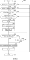
- the ECU 10 measures the elapsed time ( ⁇ t) from the point in time (t1) when the mild deceleration process was initiated. When the elapsed time ( ⁇ t) reaches a threshold value ( ⁇ t_th) at time (t2), the ECU 10 ends the mild deceleration process and resumes the following process.
- the threshold value ( ⁇ t_th) is a predetermined time, calculated as the standard time between the activation of the preceding vehicle's turn signal and the point when the preceding vehicle begins to decelerate. However, if the ECU 10 detects that the preceding vehicle V1 has begun decelerating while the mild deceleration process is being executed, it ends the mild deceleration process at that point and resumes the following process.
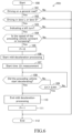
- step 201 the CPU determines whether the own vehicle is traveling on a general road based on information obtained from the navigation system 25. If the CPU determines that the own vehicle is traveling on a general road (201: Yes), it proceeds to step 202. If the CPU determines that the own vehicle is not traveling on a general road (201: No), it proceeds to step 212, where the execution of program PR2 is terminated.
- step 202 the CPU determines whether the own vehicle is traveling in lane R or lane S based on information obtained from the navigation system 25. If the CPU determines that the own vehicle is traveling in lane R or lane S (202: Yes), it proceeds to step 203. If the CPU determines that the own vehicle is not traveling in lane R or lane S (202: No), it proceeds to step 212, where the execution of program PR2 is terminated.
- the ECU 10 may execute an acceleration suppression process that controls the drive device 30 and/or the braking device 40 to prevent the own vehicle from accelerating (increasing the speed vs). For example, even if the driver presses the accelerator pedal in SCN1 or SCN2, the ECU 10 will not increase the target driving force.
- the ECU 10 can execute both the acceleration process and deceleration process during the following process.
- the ECU 10 may be configured to execute only the deceleration process during the following process. In other words, in scenes other than SCN1 and SCN2, it may be permissible for the distance D to increase beyond the target distance Dd.
Landscapes
- Engineering & Computer Science (AREA)
- Mechanical Engineering (AREA)
- Transportation (AREA)
- Automation & Control Theory (AREA)
- Physics & Mathematics (AREA)
- General Physics & Mathematics (AREA)
- Chemical & Material Sciences (AREA)
- Combustion & Propulsion (AREA)
- Atmospheric Sciences (AREA)
- Life Sciences & Earth Sciences (AREA)
- Mathematical Physics (AREA)
- Traffic Control Systems (AREA)
- Control Of Driving Devices And Active Controlling Of Vehicle (AREA)
Applications Claiming Priority (1)
| Application Number | Priority Date | Filing Date | Title |
|---|---|---|---|
| JP2023214509A JP2025098404A (ja) | 2023-12-20 | 2023-12-20 | 運転支援装置、運転支援方法、及び運転支援プログラム |
Publications (1)
| Publication Number | Publication Date |
|---|---|
| EP4574609A1 true EP4574609A1 (fr) | 2025-06-25 |
Family
ID=93926336
Family Applications (1)
| Application Number | Title | Priority Date | Filing Date |
|---|---|---|---|
| EP24221244.7A Pending EP4574609A1 (fr) | 2023-12-20 | 2024-12-18 | Dispositif d'aide à la conduite, procédé d'aide à la conduite et programme d'aide à la conduite |
Country Status (5)
| Country | Link |
|---|---|
| US (1) | US20250206305A1 (fr) |
| EP (1) | EP4574609A1 (fr) |
| JP (1) | JP2025098404A (fr) |
| KR (1) | KR20250096618A (fr) |
| CN (1) | CN120183225A (fr) |
Citations (4)
| Publication number | Priority date | Publication date | Assignee | Title |
|---|---|---|---|---|
| JP2006044590A (ja) | 2004-08-06 | 2006-02-16 | Toyota Motor Corp | 車両の減速制御装置 |
| US20150183433A1 (en) * | 2013-12-26 | 2015-07-02 | Fuji Jukogyo Kabushiki Kaisha | Vehicle control device and vehicle control method |
| DE102019109797A1 (de) * | 2019-04-12 | 2020-10-15 | Bayerische Motoren Werke Aktiengesellschaft | Verfahren und Steuereinheit zum Betrieb eines Abstandsreglers eines Fahrzeugs |
| US20210253136A1 (en) * | 2020-02-13 | 2021-08-19 | Honda Motor Co., Ltd. | Vehicle control device, vehicle control method, and storage medium |
Family Cites Families (3)
| Publication number | Priority date | Publication date | Assignee | Title |
|---|---|---|---|---|
| JP4941059B2 (ja) * | 2007-04-02 | 2012-05-30 | 株式会社豊田中央研究所 | 運転支援装置 |
| JP6344147B2 (ja) * | 2014-08-28 | 2018-06-20 | 日産自動車株式会社 | 車間距離制御装置 |
| JP2019168960A (ja) * | 2018-03-23 | 2019-10-03 | トヨタ自動車株式会社 | 運転支援装置 |
-
2023
- 2023-12-20 JP JP2023214509A patent/JP2025098404A/ja active Pending
-
2024
- 2024-11-26 US US18/960,673 patent/US20250206305A1/en active Pending
- 2024-12-18 EP EP24221244.7A patent/EP4574609A1/fr active Pending
- 2024-12-18 CN CN202411867675.6A patent/CN120183225A/zh active Pending
- 2024-12-19 KR KR1020240190925A patent/KR20250096618A/ko active Pending
Patent Citations (4)
| Publication number | Priority date | Publication date | Assignee | Title |
|---|---|---|---|---|
| JP2006044590A (ja) | 2004-08-06 | 2006-02-16 | Toyota Motor Corp | 車両の減速制御装置 |
| US20150183433A1 (en) * | 2013-12-26 | 2015-07-02 | Fuji Jukogyo Kabushiki Kaisha | Vehicle control device and vehicle control method |
| DE102019109797A1 (de) * | 2019-04-12 | 2020-10-15 | Bayerische Motoren Werke Aktiengesellschaft | Verfahren und Steuereinheit zum Betrieb eines Abstandsreglers eines Fahrzeugs |
| US20210253136A1 (en) * | 2020-02-13 | 2021-08-19 | Honda Motor Co., Ltd. | Vehicle control device, vehicle control method, and storage medium |
Also Published As
| Publication number | Publication date |
|---|---|
| KR20250096618A (ko) | 2025-06-27 |
| CN120183225A (zh) | 2025-06-20 |
| JP2025098404A (ja) | 2025-07-02 |
| US20250206305A1 (en) | 2025-06-26 |
Similar Documents
| Publication | Publication Date | Title |
|---|---|---|
| EP3446941B1 (fr) | Appareil d'aide à la conduite de véhicules | |
| US8751134B2 (en) | Method and device for regulating the speed of a motor vehicle | |
| KR101883063B1 (ko) | 차량 주행 제어 장치 | |
| US12036988B2 (en) | Method and control unit for operating an adaptive cruise controller | |
| EP1349131A1 (fr) | Appareil de prevention des collisions entre vehicules | |
| US11260860B2 (en) | Vehicle control device | |
| US12515644B2 (en) | Vehicle deceleration assistance apparatus | |
| US20230286505A1 (en) | Driving assistance apparatus | |
| JP2022114062A (ja) | 車両運転支援装置 | |
| JP7700718B2 (ja) | 減速支援装置 | |
| JP2023103648A (ja) | 加速抑制装置 | |
| EP4574609A1 (fr) | Dispositif d'aide à la conduite, procédé d'aide à la conduite et programme d'aide à la conduite | |
| JP2020069953A (ja) | 車両用運転支援装置 | |
| US20240336265A1 (en) | Vehicle control device, vehicle control method and program | |
| US12351178B2 (en) | Driving assistance device, driving assistance method, and driving assistance program | |
| JP7211291B2 (ja) | 車両走行制御装置 | |
| CN116215524B (zh) | 驾驶支援装置 | |
| JP7678406B2 (ja) | 運転支援装置 | |
| US12227180B2 (en) | Driving support device, driving support method, and driving support program | |
| US11897467B2 (en) | Vehicle driving assist apparatus | |
| JP2025074390A (ja) | 衝突防止装置 | |
| JP2025076153A (ja) | 走行制御装置 | |
| CN120840609A (zh) | 自适应巡航控制系统acc的控制方法和设备 |
Legal Events
| Date | Code | Title | Description |
|---|---|---|---|
| PUAI | Public reference made under article 153(3) epc to a published international application that has entered the european phase |
Free format text: ORIGINAL CODE: 0009012 |
|
| STAA | Information on the status of an ep patent application or granted ep patent |
Free format text: STATUS: REQUEST FOR EXAMINATION WAS MADE |
|
| 17P | Request for examination filed |
Effective date: 20241218 |
|
| AK | Designated contracting states |
Kind code of ref document: A1 Designated state(s): AL AT BE BG CH CY CZ DE DK EE ES FI FR GB GR HR HU IE IS IT LI LT LU LV MC ME MK MT NL NO PL PT RO RS SE SI SK SM TR |