EP4574629A1 - Structure de carrosserie inférieure de véhicule - Google Patents
Structure de carrosserie inférieure de véhicule Download PDFInfo
- Publication number
- EP4574629A1 EP4574629A1 EP24221636.4A EP24221636A EP4574629A1 EP 4574629 A1 EP4574629 A1 EP 4574629A1 EP 24221636 A EP24221636 A EP 24221636A EP 4574629 A1 EP4574629 A1 EP 4574629A1
- Authority
- EP
- European Patent Office
- Prior art keywords
- vehicle
- rocker
- projecting portion
- joined
- width direction
- Prior art date
- Legal status (The legal status is an assumption and is not a legal conclusion. Google has not performed a legal analysis and makes no representation as to the accuracy of the status listed.)
- Pending
Links
Images

Classifications
-
- B—PERFORMING OPERATIONS; TRANSPORTING
- B62—LAND VEHICLES FOR TRAVELLING OTHERWISE THAN ON RAILS
- B62D—MOTOR VEHICLES; TRAILERS
- B62D21/00—Understructures, i.e. chassis frame on which a vehicle body may be mounted
- B62D21/15—Understructures, i.e. chassis frame on which a vehicle body may be mounted having impact absorbing means, e.g. a frame designed to permanently or temporarily change shape or dimension upon impact with another body
- B62D21/157—Understructures, i.e. chassis frame on which a vehicle body may be mounted having impact absorbing means, e.g. a frame designed to permanently or temporarily change shape or dimension upon impact with another body for side impacts
-
- B—PERFORMING OPERATIONS; TRANSPORTING
- B62—LAND VEHICLES FOR TRAVELLING OTHERWISE THAN ON RAILS
- B62D—MOTOR VEHICLES; TRAILERS
- B62D25/00—Superstructure or monocoque structure sub-units; Parts or details thereof not otherwise provided for
- B62D25/02—Side panels
- B62D25/025—Side sills thereof
-
- B—PERFORMING OPERATIONS; TRANSPORTING
- B62—LAND VEHICLES FOR TRAVELLING OTHERWISE THAN ON RAILS
- B62D—MOTOR VEHICLES; TRAILERS
- B62D21/00—Understructures, i.e. chassis frame on which a vehicle body may be mounted
- B62D21/02—Understructures, i.e. chassis frame on which a vehicle body may be mounted comprising longitudinally or transversely arranged frame members
-
- B—PERFORMING OPERATIONS; TRANSPORTING
- B62—LAND VEHICLES FOR TRAVELLING OTHERWISE THAN ON RAILS
- B62D—MOTOR VEHICLES; TRAILERS
- B62D21/00—Understructures, i.e. chassis frame on which a vehicle body may be mounted
- B62D21/15—Understructures, i.e. chassis frame on which a vehicle body may be mounted having impact absorbing means, e.g. a frame designed to permanently or temporarily change shape or dimension upon impact with another body
-
- B—PERFORMING OPERATIONS; TRANSPORTING
- B60—VEHICLES IN GENERAL
- B60Y—INDEXING SCHEME RELATING TO ASPECTS CROSS-CUTTING VEHICLE TECHNOLOGY
- B60Y2306/00—Other features of vehicle sub-units
- B60Y2306/09—Reducing noise
Definitions
- the present disclosure relates to a vehicle lower body structure.
- JP-A Japanese Patent Application Laid-open
- JP-A No. 2018-188086 discloses an invention relating to a vehicle body lower portion structure.
- a box-shaped bulkhead is provided inside a rocker.
- the cross-section of the rocker may deform so as to expand and contract in the vehicle up-down direction while the vehicle is moving, resulting in the propagation of road noise to the occupant and a reduction in the ride quality of the vehicle.
- the present disclosure obtains a vehicle lower body structure that can improve the ride quality of a vehicle.
- a vehicle lower body structure pertaining to a first aspect includes: a rocker configuring a part of a vehicle lower side of a vehicle side portion, the rocker disposed along a vehicle front-rear direction; and a reinforcement including a body portion provided inside the rocker and a projecting portion that projects in a vehicle up-down direction from the body portion and that is joined to a wall surface of the rocker positioned on a projecting direction side of the projecting portion.
- a part of the vehicle lower side of the vehicle side portion is configured by the rocker, and the rocker is disposed along the vehicle front-rear direction.
- the cross-section of the rocker may deform so as to expand and contract in the vehicle up-down direction while the vehicle is moving, resulting in the propagation of road noise to the occupant and a reduction in the ride quality of the vehicle.
- the rocker is reinforced by the reinforcement that includes the body portion and the projecting portion.
- the body portion is provided inside the rocker, and the projecting portion projects in the vehicle up-down direction from the body portion and is joined to the wall surface of the rocker that is positioned on the projecting direction side of the projecting portion.
- the projecting portion and the body portion resist the deformation of the rocker, with the result that the rocker is less likely to be deformed by the loads. That is, in the present aspect, the rigidity of the rocker with respect to loads in the vehicle up-down direction can be improved by the reinforcement.
- a vehicle lower body structure pertaining to a second aspect is the vehicle lower body structure pertaining to the first aspect, and the body portion is configured such that an inside of the body portion is an impact absorber that is divided in a vehicle width direction, a first projecting portion configuring the projecting portion projects in a vehicle upward direction from the impact absorber and the first projecting portion is joined to a vehicle upper part of the rocker, and a second projecting portion configuring the projecting portion projects in a vehicle downward direction from the impact absorber and the second projecting portion is joined to a vehicle lower part of the rocker.
- the vehicle lower body structure pertaining to the second aspect includes the impact absorber whose inside is divided in the vehicle width direction, and in the impact absorber plural spaces are formed in the vehicle width direction.
- the parts of the impact absorber around the spaces become crushed and can thereby absorb the impact energy.
- the first projecting portion projects in the vehicle upward direction from the impact absorber and is joined to the vehicle upper part of the rocker
- the second projecting portion projects in the vehicle downward direction from the impact absorber and is joined to the vehicle lower part of the rocker.
- a vehicle lower body structure pertaining to a third aspect is the vehicle lower body structure pertaining to the second aspect, and the first projecting portion and the second projecting portion are disposed as a set as viewed in the vehicle up-down direction, and the first projecting portion and the second projecting portion are disposed on a same side in the vehicle width direction relative to a vehicle width direction center position of the rocker.
- the first projecting portion and the second projecting portion are disposed as a set as viewed in the vehicle up-down direction. Additionally, the first projecting portion and the second projecting portion are disposed on the same side in the vehicle width direction relative to the vehicle width direction center position of the rocker.
- Loads received by the first projecting portion from the vehicle upper part of the rocker can be supported by the second projecting portion, and loads received by the second projecting portion from the vehicle lower part of the rocker can be supported by the first projecting portion.
- the rigidity of the rocker with respect to loads in the vehicle up-down direction can be improved.
- a vehicle lower body structure pertaining to a fourth aspect is the vehicle lower body structure pertaining to any one of the first aspect to the third aspect, and the body portion is joined to an outer part and an inner part, in the vehicle width direction, of the rocker.
- the body portion is joined to the outer part and the inner part, in the vehicle width direction, of the rocker, and expansion and contraction of the rocker in the vehicle width direction are restrained by the body portion.
- the rigidity of the rocker with respect to loads in the vehicle up-down direction can be further improved.
- a vehicle lower body structure pertaining to a fifth aspect is the vehicle lower body structure pertaining to any one of the first aspect to the fourth aspect, and the reinforcement further includes a shared panel that is provided inside the rocker, that extends in the vehicle up-down direction, and that interconnects a vehicle upper part and a vehicle lower part of the rocker.
- the reinforcement includes the shared panel provided inside the rocker.
- the shared panel extends in the vehicle up-down direction, and the vehicle upper part and the vehicle lower part of the rocker are interconnected by the shared panel. Expansion and contraction of the rocker in the vehicle up-down direction are restrained by the shared panel, with the result that the rigidity of the rocker with respect to loads in the vehicle up-down direction can be further improved.
- a vehicle lower body structure pertaining to a sixth aspect is the vehicle lower body structure pertaining to any one of the first aspect to the fifth aspect, and the projecting portion is formed integrally with at least one of a vehicle upper part or a vehicle lower part of the body portion.
- the projecting portion is formed integrally with at least one of the vehicle upper part or the vehicle lower part of the body portion.
- the number of parts configuring the vehicle can be reduced and the manufacturing process of the vehicle can be simplified.
- a vehicle lower body structure pertaining to a seventh aspect is the vehicle lower body structure pertaining to the sixth aspect, and the projecting portion and a part of the body portion at which the projecting portion is provided are formed by the same sheet material.
- the body portion and the projecting portion can be integrally formed by bending a sheet material, with the result that the manufacturing process of the vehicle can be further simplified.
- a vehicle lower body structure pertaining to an eighth aspect is the vehicle lower body structure pertaining to any one of the first aspect to the seventh aspect, and a joint surface of the projecting portion joined to the rocker and the part of the rocker joined to the joint surface are in parallel as viewed in the vehicle front-rear direction.
- the joint surface of the projecting portion joined to the rocker and the part of the rocker joined to the joint surface are in parallel as viewed in the vehicle front-rear direction, and the projecting portion and the rocker can be brought into planar contact with each other.
- the vehicle lower body structure pertaining to the present disclosure has the effect that it can improve the ride quality of a vehicle.
- FIG. 1 and FIG. 2 A first embodiment of the vehicle lower body structure pertaining to the present disclosure will be described below using FIG. 1 and FIG. 2 .
- arrow FR shown where appropriate in the drawings indicates a vehicle forward direction
- arrow UP indicates a vehicle upward direction
- arrow LH indicates a leftward direction in a vehicle width direction.
- the vehicle 10 basically has a bilaterally symmetrical configuration, so mainly configurations of the vehicle width direction left part of the vehicle 10 will be described below, and description of the vehicle width direction right part will be omitted as appropriate.
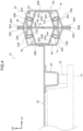
- the vehicle 10 is configured to include a vehicle body 12, a power unit such as a motor (not shown in the drawings) installed in the vehicle 10, and a battery pack 14 attached to the vehicle body 12.
- the power unit is driven upon receiving a supply of power from the battery pack 14, and the vehicle 10 travels on driving power generated by the power unit.
- the vehicle body 12 includes a cabin 16, and the vehicle lower part of the cabin 16 is configured by a floor portion 18.
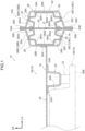
- the floor portion 18 is configured to include a floor panel 20, rockers 22, and side members 24.
- the floor panel 20 is formed by stamping a steel sheet and extends in the vehicle front-rear direction and the vehicle width direction as viewed in the vehicle up-down direction.
- a left-right pair of the rockers 22 are disposed along the vehicle front-rear direction at outer edge portions, in the vehicle width direction, of the floor panel 20. It will be noted that the rockers 22 configure a part of a vehicle lower side of a vehicle side portion 10A.
- the rockers 22 are made of steel, extend in the vehicle front-rear direction, and are each configured to include a rocker outer panel 26 that configures the vehicle width direction outer part thereof and a rocker inner panel 28 that configures the vehicle width direction inner part thereof.
- the rocker outer panel 26 includes an upper wall portion 26A that configures the vehicle upper part thereof, a side wall portion 26B that configures the vehicle width direction outer part thereof, a lower wall portion 26C that configures the vehicle lower part thereof, and a pair of flange portions 26D. Furthermore, the cross-sectional shape of the rocker outer panel 26 as viewed in the vehicle front-rear direction is configured in the shape of a hat that opens inward in the vehicle width direction.
- the rocker inner panel 28 includes an upper wall portion 28A that configures the vehicle upper part thereof, a side wall portion 28B that configures the vehicle width direction inner part thereof, a lower wall portion 28C that configures the vehicle lower part thereof, and a pair of flange portions 28D. Furthermore, the cross-sectional shape of the rocker inner panel 28 as viewed in the vehicle front-rear direction is configured in the shape of a hat that opens outward in the vehicle width direction. It will be noted that a vehicle width direction outer end portion 20A of the floor panel 20 is joined to the side wall portion 28B by joints (not shown in the drawings) formed by welding or the like.
- the flange portions 26D of the rocker outer panel 26 and the flange portions 28D of the rocker inner panel 28 are joined to each other by joints (not shown in the drawings) formed by welding or the like, so that the rocker 22 has a closed cross-sectional structure whose cross-sectional shape as viewed in the vehicle front-rear direction is a substantially hexagonal closed cross-section.
- the side members 24 are made of steel, extend in the vehicle front-rear direction, and are disposed on both sides, in the vehicle width direction, of the floor panel 20 on the vehicle lower side of the floor panel 20. It will be noted that the side members 24 are positioned inward in the vehicle width direction relative to the rockers 22.
- each of the side members 24 as viewed in the vehicle front-rear direction is configured in the shape of a hat that opens in the upward direction, and flange portions 24A thereof are joined to the floor panel 20 by joints (not shown in the drawings) formed by welding or the like. Furthermore, the side members 24 configure with the floor panel 20 closed cross-sectional structural units as a result of being joined to the floor panel 20. In the present embodiment, the battery pack 14 is attached to the side members 24.
- the battery pack 14 includes a battery case 30 whose main part is configured by an aluminum alloy and a battery module (not shown in the drawings) disposed inside the battery case 30.
- the battery case 30 includes a body portion 30A that houses the battery module and a base portion 30B that configures the vehicle lower part of the battery case 30.
- the battery case 30 is secured to the vehicle body 12 as a result of the base portion 30B being attached by attachment members (not shown the drawings) to the side members 24 in a state in which the main part of the body portion 30A is housed between the side members 24 and a state in which mount members 32 are interposed between the base portion 30B and the side members 24. It will be noted that the height position of a part of the battery pack 14 overlaps the rockers 22 as viewed in the vehicle width direction.
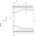
- the vehicle lower body structure has a characteristic in that the rockers 22 are reinforced by reinforcements 34 provided inside the rockers 22.
- the configuration of the reinforcements 34 will be described in detail below.
- the first projecting portion 36B is formed in the vehicle width direction central portion of the upper wall 36A1, extends in the vehicle front-rear direction, projects in the upward direction from the upper wall 36A1 as viewed in the vehicle front-rear direction, and is configured in the shape of a U that opens in the downward direction.
- an upper surface 36B1 of the first projecting portion 36B is configured as a joint surface joined to the upper wall portion 26A of the rocker outer panel 26 and is in parallel to the upper wall portion 26A as viewed in the vehicle front-rear direction.
- the upper surface 36B1 and the wall surface of the upper wall portion 26A of the rocker outer panel 26 are joined to each other by joints (not shown in the drawings) formed by friction stir welding or the like.
- first projecting portion 36B and the second projecting portion 36C are disposed as a set so as to overlap each other as viewed in the vehicle up-down direction and are positioned outward in the vehicle width direction relative to a center, in the vehicle width direction, of the rocker 22, more specifically, relative to a center of gravity G of the cross-section of the rocker 22 as viewed in the vehicle front-rear direction.
- the inner reinforcement member 38 is formed by stamping a single steel sheet, extends in the vehicle front-rear direction, and is configured to include a base portion 38A that configures the main part thereof, a first projecting portion 38B configuring a projecting portion, and a second projecting portion 38C configuring a projecting portion.
- the shared panel 66 has the same configuration as the shared panel 40, and an upper end portion 66A thereof is sandwiched between and joined by joints (not shown in the drawings) formed by welding or the like to the rocker outer panel 26 and the rocker inner panel 28.
Landscapes
- Engineering & Computer Science (AREA)
- Chemical & Material Sciences (AREA)
- Combustion & Propulsion (AREA)
- Transportation (AREA)
- Mechanical Engineering (AREA)
- Body Structure For Vehicles (AREA)
Applications Claiming Priority (1)
| Application Number | Priority Date | Filing Date | Title |
|---|---|---|---|
| JP2023217308A JP2025100152A (ja) | 2023-12-22 | 2023-12-22 | 車両下部構造 |
Publications (1)
| Publication Number | Publication Date |
|---|---|
| EP4574629A1 true EP4574629A1 (fr) | 2025-06-25 |
Family
ID=93926349
Family Applications (1)
| Application Number | Title | Priority Date | Filing Date |
|---|---|---|---|
| EP24221636.4A Pending EP4574629A1 (fr) | 2023-12-22 | 2024-12-19 | Structure de carrosserie inférieure de véhicule |
Country Status (5)
| Country | Link |
|---|---|
| US (1) | US20250206379A1 (fr) |
| EP (1) | EP4574629A1 (fr) |
| JP (1) | JP2025100152A (fr) |
| KR (1) | KR20250098926A (fr) |
| CN (1) | CN120191437A (fr) |
Citations (5)
| Publication number | Priority date | Publication date | Assignee | Title |
|---|---|---|---|---|
| DE102018003558A1 (de) * | 2018-05-02 | 2018-11-29 | Daimler Ag | Kraftverteileranordnung für ein Fahrzeug sowie Verstärkungseinrichtung eingerichtet zur Verwendung in einer Kraftverteileranordnung |
| JP2018188086A (ja) | 2017-05-11 | 2018-11-29 | 本田技研工業株式会社 | 車体下部構造 |
| US10486746B2 (en) * | 2017-02-17 | 2019-11-26 | Honda Motor Co., Ltd. | Substructure of vehicle body |
| US20200114973A1 (en) * | 2018-10-12 | 2020-04-16 | Toyota Jidosha Kabushiki Kaisha | Vehicle lower section structure |
| US10752292B2 (en) * | 2017-04-28 | 2020-08-25 | Toyota Jidosha Kabushiki Kaisha | Vehicle lower section structure |
Family Cites Families (3)
| Publication number | Priority date | Publication date | Assignee | Title |
|---|---|---|---|---|
| JPH01165779U (fr) * | 1988-05-16 | 1989-11-20 | ||
| DE112015001712T5 (de) * | 2014-04-09 | 2017-01-12 | Honda Motor Co., Ltd. | Fahrzeugrahmenkonstruktion und Verfahren |
| US9758193B2 (en) * | 2015-02-10 | 2017-09-12 | Honda Motor Co., Ltd. | Structural reinforcement member for a vehicle body |
-
2023
- 2023-12-22 JP JP2023217308A patent/JP2025100152A/ja active Pending
-
2024
- 2024-11-22 CN CN202411681556.1A patent/CN120191437A/zh active Pending
- 2024-11-25 KR KR1020240169403A patent/KR20250098926A/ko active Pending
- 2024-12-16 US US18/981,652 patent/US20250206379A1/en active Pending
- 2024-12-19 EP EP24221636.4A patent/EP4574629A1/fr active Pending
Patent Citations (5)
| Publication number | Priority date | Publication date | Assignee | Title |
|---|---|---|---|---|
| US10486746B2 (en) * | 2017-02-17 | 2019-11-26 | Honda Motor Co., Ltd. | Substructure of vehicle body |
| US10752292B2 (en) * | 2017-04-28 | 2020-08-25 | Toyota Jidosha Kabushiki Kaisha | Vehicle lower section structure |
| JP2018188086A (ja) | 2017-05-11 | 2018-11-29 | 本田技研工業株式会社 | 車体下部構造 |
| DE102018003558A1 (de) * | 2018-05-02 | 2018-11-29 | Daimler Ag | Kraftverteileranordnung für ein Fahrzeug sowie Verstärkungseinrichtung eingerichtet zur Verwendung in einer Kraftverteileranordnung |
| US20200114973A1 (en) * | 2018-10-12 | 2020-04-16 | Toyota Jidosha Kabushiki Kaisha | Vehicle lower section structure |
Also Published As
| Publication number | Publication date |
|---|---|
| US20250206379A1 (en) | 2025-06-26 |
| CN120191437A (zh) | 2025-06-24 |
| JP2025100152A (ja) | 2025-07-03 |
| KR20250098926A (ko) | 2025-07-01 |
Similar Documents
| Publication | Publication Date | Title |
|---|---|---|
| CN108791522B (zh) | 车辆下部结构 | |
| US10486746B2 (en) | Substructure of vehicle body | |
| US10464406B2 (en) | Vehicle body bottom structure | |
| CN110588800B (zh) | 车身下部结构 | |
| CN109383257B (zh) | 车辆侧部构造 | |
| JP4858183B2 (ja) | 車体下部構造 | |
| US20190275874A1 (en) | Lower vehicle body structure | |
| JP7535249B2 (ja) | 車両用バッテリパックの固定構造 | |
| CN112739611B (zh) | 车身下部结构 | |
| JP2020011640A (ja) | 車体側部構造 | |
| US20250010918A1 (en) | Lower structure of automotive body and side sill structure of automobile | |
| JP7192904B2 (ja) | 車両下部構造 | |
| JP2024121020A (ja) | 車両下部構造 | |
| JP7665975B2 (ja) | 車両用バッテリパックの構造 | |
| JP2021091341A (ja) | 車体側部構造 | |
| EP4574495A1 (fr) | Structure de carrosserie inférieure de véhicule | |
| EP4574629A1 (fr) | Structure de carrosserie inférieure de véhicule | |
| US20240387920A1 (en) | Case side wall of battery case | |
| JP7850108B2 (ja) | 自動車用バッテリーケースおよびその製造方法 | |
| US20250214655A1 (en) | Vehicle lower part structure | |
| EP2428432B1 (fr) | Châssis antérieur d'un véhicule | |
| US20240387921A1 (en) | Case side wall of battery case | |
| WO2025047137A1 (fr) | Structure de carrosserie de véhicule | |
| CN115610525A (zh) | 用于车辆的地板骨架和具有其的车辆 | |
| CN120792960A (zh) | 车辆下部结构 |
Legal Events
| Date | Code | Title | Description |
|---|---|---|---|
| PUAI | Public reference made under article 153(3) epc to a published international application that has entered the european phase |
Free format text: ORIGINAL CODE: 0009012 |
|
| STAA | Information on the status of an ep patent application or granted ep patent |
Free format text: STATUS: REQUEST FOR EXAMINATION WAS MADE |
|
| 17P | Request for examination filed |
Effective date: 20241219 |
|
| AK | Designated contracting states |
Kind code of ref document: A1 Designated state(s): AL AT BE BG CH CY CZ DE DK EE ES FI FR GB GR HR HU IE IS IT LI LT LU LV MC ME MK MT NL NO PL PT RO RS SE SI SK SM TR |