EP4574643A1 - Mât principal d'un voilier - Google Patents
Mât principal d'un voilier Download PDFInfo
- Publication number
- EP4574643A1 EP4574643A1 EP24216085.1A EP24216085A EP4574643A1 EP 4574643 A1 EP4574643 A1 EP 4574643A1 EP 24216085 A EP24216085 A EP 24216085A EP 4574643 A1 EP4574643 A1 EP 4574643A1
- Authority
- EP
- European Patent Office
- Prior art keywords
- mainmast
- upright
- connecting portion
- airfoil
- axis
- Prior art date
- Legal status (The legal status is an assumption and is not a legal conclusion. Google has not performed a legal analysis and makes no representation as to the accuracy of the status listed.)
- Pending
Links
Images


Classifications
-
- B—PERFORMING OPERATIONS; TRANSPORTING
- B63—SHIPS OR OTHER WATERBORNE VESSELS; RELATED EQUIPMENT
- B63H—MARINE PROPULSION OR STEERING
- B63H9/00—Marine propulsion provided directly by wind power
- B63H9/04—Marine propulsion provided directly by wind power using sails or like wind-catching surfaces
- B63H9/06—Types of sail; Constructional features of sails; Arrangements thereof on vessels
- B63H9/061—Rigid sails; Aerofoil sails
-
- B—PERFORMING OPERATIONS; TRANSPORTING
- B63—SHIPS OR OTHER WATERBORNE VESSELS; RELATED EQUIPMENT
- B63H—MARINE PROPULSION OR STEERING
- B63H9/00—Marine propulsion provided directly by wind power
- B63H9/04—Marine propulsion provided directly by wind power using sails or like wind-catching surfaces
-
- B—PERFORMING OPERATIONS; TRANSPORTING
- B63—SHIPS OR OTHER WATERBORNE VESSELS; RELATED EQUIPMENT
- B63H—MARINE PROPULSION OR STEERING
- B63H9/00—Marine propulsion provided directly by wind power
- B63H9/04—Marine propulsion provided directly by wind power using sails or like wind-catching surfaces
- B63H9/08—Connections of sails to masts, spars, or the like
-
- B—PERFORMING OPERATIONS; TRANSPORTING
- B63—SHIPS OR OTHER WATERBORNE VESSELS; RELATED EQUIPMENT
- B63B—SHIPS OR OTHER WATERBORNE VESSELS; EQUIPMENT FOR SHIPPING
- B63B35/00—Vessels or similar floating structures specially adapted for specific purposes and not otherwise provided for
- B63B2035/009—Wind propelled vessels comprising arrangements, installations or devices specially adapted therefor, other than wind propulsion arrangements, installations, or devices, such as sails, running rigging, or the like, and other than sailboards or the like or related equipment
Definitions
- the present invention relates to a mainmast of a sailing boat, which is designed, in particular, for offshore sailing competitions, to which the following description will make explicit reference without thereby losing generality.
- the present invention finds advantageous but not exclusive application in a sailing boat having a single hull and provided with hydrodynamic lifting foils, usually indicated with the English term “hydrofoil”, or more simply “foil”, which are configured so as to have a hydrodynamic lift that is able to support the weight of the vessel and keep the hull out of the water when the vessel is sailing at relatively high speeds.
- a sailing boat essentially comprises a hull, closed at the top by a deck, at least one mainmast that protrudes vertically from the hull and from the deck, a forestay that connects the upper end portion of the mainmast to the bow of the hull, a main sail known as mainsail, hoisted on the mainmast, and a front sail known as jib, hoisted on the forestay.
- the mainsail In regular sailing conditions, the mainsail is used to sail upwind, whereas the jib helps the boat tack correctly and allows to maintain control of the bow.
- hydrodynamic lifting foils or hydrofoils or even more simply foils, are mounted on racing sailing boats, in order to keep the hull out of the water when given cruising speeds are reached, in a condition that is commonly referred to as "flying on the surface of the water", in order to reduce hydrodynamic resistance during navigation.
- hydrofoils have been used both on multi-hull sailing boats, especially on trimarans, and on mono-hull sailing boats, in order to maximize the speed of the boats designed for sports competitions.
- the mainmast has also been the subject of innovations, in particular by providing a cross-section area having an elongated drop shape, in order to define an aerofoil.
- the mainmast is defined by a symmetrical, vertically extruded profile, which often also has the ability to rotate about its vertical axis with respect to the deck of the hull, in order to try to align the front edge, or leading edge, of the airfoil defined by the mainmast with respect to the direction of the apparent wind, namely, the AWA ("apparent wind angle").
- the presence of the jib in front of the mainmast generally has the effect of locally varying (in particular the effect of reducing) the angle of the air flowing towards the leading edge of the mainmast.
- the object of the invention is therefore to satisfy the above-mentioned needs, preferably in a simple and/or effective and/or inexpensive manner.
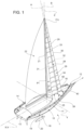
- reference number 1 denotes, as a whole, a sailing boat, of the monohull type (illustrated partially and by simplifying some parts).
- the sailing boat 1 comprises a hull 11 extending along a longitudinal axis X between a forward end or bow, indicated by reference 12, and a rear end or stern, indicated by reference 13.
- the longitudinal axis X coincides with a normal advancement direction V of the sailing boat 1.
- the hull 11 extends, furthermore, in width and height along a transverse axis Y and along an axis Z, perpendicular to one another and to the longitudinal axis X, so as to form a Cartesian triplet of orthogonal axes, fixed with respect to the hull 11.
- the longitudinal axis X, the transverse axis Y and the axis Z are commonly referred to as the roll axis, the pitch axis, and the yaw axis, respectively.
- the hull 11 is delimited laterally by opposite sides 14, 15, extending between the bow 12 and the stern 13, and is normally closed at the top by a deck 16.
- the sailing boat 1 preferably comprises, furthermore, a keel or centreboard 18, which protrudes downwards along an axis parallel to the axis Z starting from a portion 19 of the hull 11 arranged in an intermediate position between the bow 12 and the stern 13, and centrally between the sides 14, 15 of the hull 11.
- the centreboard 18 has a lower end that supports or defines a bulb 20, having a mass (for example of about 8-10 tons) so as to place the centre of gravity of the sailing boat 1 in a relatively low position, in particular to allow the self-righting of the sailing boat 1 even in the event of a totally capsizing.
- the sailing boat 1 is of the type suitable for offshore sailing competitions and is provided with lateral arms, known and not illustrated, provided with respective hydrofoils or more simply foils (also known and not illustrated) and connected to the hull 11 so as to be independently movable between a lowered position, in which they immerse their foil in the water, and a raised position, in which they keep their foil out of the water.
- the sailing boat 1 comprises, furthermore, a mainmast 21 having a support base S mounted in a fixed position with respect to the hull 11 and an upright P, which protrudes upwards from the support base S along an axis which, in the specific example illustrated, coincides with the axis Z.
- the upright P of the mainmast 21 defines an airfoil or aerofoil, better shown in Figures 3 and 4 : such airfoil is configured in order to have two opposite surfaces 21a and 21b, which are convex, extend from a leading edge 50 and are symmetrical with one another with respect to an ideal median plane, on which the axis Z and the leading edge 50 lie.
- the surfaces 21a and 21b are arranged, one, upwind and, the other, downwind (in the example illustrated, the surface 21b is downwind).
- the leading edge 50 of the upright P is rectilinear and parallel to the axis Z, and the cross-sections of its airfoil have an invariant shape throughout its axial height.
- the dimensions of the cross-sections of the upright P also remain equal to one another, throughout its height, without tapering.
- the sailing boat 1 comprises, furthermore, a mainsail 22, hoisted in a known manner and not described in detail on the mainmast 21.
- the mainsail 22 has opposite surfaces, arranged upwind and downwind, respectively.
- the sailing boat 1 comprises, furthermore, one or more jibs, in the case illustrated two, indicated respectively with the references 25 and 26, which are arranged in front of the mainmast 21, namely, between the latter and the bow 12, and are configured, when cross-sectioned with horizontal section planes, according to given aerofoils in each cross-section.
- the jibs 25 and 26 have respective opposite surfaces, arranged upwind and downwind, respectively.
- the jibs 25 and 26 define respective slats with respect to the airfoil defined by a lower portion P1 of the upright P, which is immediately adjacent towards the stern.
- the jib 26 is instead arranged in front of the jib 25, precisely between the latter and the bow 12.
- the sailing boat 1 comprises, furthermore, one or more actuators (not illustrated) to move the ribs 31, 32 and/or the support elements 29, 30 along planes transverse to the longitudinal axis X and to the vertical axis Z.
- a first actuator is used to move the support element 29 and a second actuator, different from the first, to move the support element 30.
- the air flow that impacts the lower portion P1 of the upright P has an angle of incidence that varies precisely as the height varies.
- the aerodynamic operating conditions of the mainmast 21, caused by the air flows directed towards the upright P are potentially different as the height position along the upright P varies.
- the mainmast 21 comprises a fairing 60, which is arranged in front of at least a part of the lower portion P1, so as to cover the same towards the bow.
- the fairing 60 is formed by a relatively thin-walled semi-shell, made of flexible material, namely, elastically deformable, having two surfaces opposite to one another, one facing the lower portion P1 of the upright P and the other, indicated by the reference 61, exposed to the wind.
- the surface 61 defines an airfoil which, in practice, covers and replaces that of the lower portion P1.
- the surface 61 comprises a leading edge 62 and two lateral surfaces 63a and 63b, which extend from the leading edge 62 on opposite sides of the fairing 60 so as to form a series of aerofoils (illustrated schematically and indicated with the references Q1, Q2, Q3, etc.) when the fairing 60 is cross sectioned by any section plane orthogonal to the axis Z.
- the fairing 60 comprises a first and a second connecting portion, indicated with the references 64 and 65, arranged in positions spaced apart from one another along the axis Z and coupled so as to support the fairing 60 and keep the same in front of the lower portion P1.
- the connecting portion 64 is coupled to the upright P so as to rotate together with the upright P about the axis Z with respect to the connecting portion 65 and therefore twist the airfoil defined by the surface 61 due to the rotation.
- Figures 3 and 4 show, by way of example, a rotation of the upright P in a clockwise direction, with respect to a reference condition in which the leading edge 62 lies in the ideal median plane of the upright P.
- the leading edge 62 no longer lies in the ideal median plane of the upright P, but takes on a curved shape.
- the aerofoils Q1, Q2, Q3, etc. are progressively rotated about the axis Z, with increasingly greater rotation angles going from the connecting portion 65 towards the connecting portion 64, or vice versa.
- the connecting portion 65 is coupled to the support base S.
- it could be coupled to a different support element, however fixed with respect to the hull 11.
- the connecting portion 65 is defined by a lower end of the fairing 60, and is fixed to the support base (S), for example, by gluing, rivets, screws, etc.
- the connecting portion 65 is wider than the upright P and is spaced from the leading edge 50 of the lower portion P1, so as to define, in a radial direction with respect to the axis Z, an inner cavity between the fairing 60 and the same lower portion P1. Said spacing facilitates the elastic deformation of the fairing 60 during the rotation of the upright P about the axis Z.
- the fairing 60 ends with respective end flaps 66, which extend parallel to the axis Z along the lower portion P1 and rest on the surfaces 21a and 21b, respectively, in positions that are substantially diametrically opposite to one another.
- the connecting portion 64 is defined by an upper end of the fairing 60 and is fixed to the upright P, for example by gluing. At this upper end, the fairing 60 completely rests onto the airfoil of the upright P, namely, it completely rests onto the surfaces 21a and 21b and on the leading edge 50, without defining any empty space with respect to the upright P; in other words, at the upper end, the airfoil of the fairing 60 and the airfoil of the upright P overlap and, given the negligible thickness of the fairing 60, they extend along the axis Z one after the other substantially without interruption.
- the fairing 60 comprises a tapered portion 67, arranged in an axial position that is intermediate between the connecting portions 64 and 65 and is immediately adjacent to the connecting portion 64.
- the cross-sections of the fairing 60 (defining the aerofoils Q1, Q2, Q3, etc., mentioned above) have different dimensions one from the other, based on the different height position, as well as having a different orientation (or angle) based on the rotation of the upright P about the axis Z.
- the fairing 60 by deforming, automatically adapts the orientation of the leading edge 62 based on the height position, in response to the rotation of the upright P.
- This automatic twisting of the airfoil of the fairing 60 allows the orientation of the aerofoils Q1, Q2, Q3, etc., to be automatically adapted to the different angle of incidence of the air flow coming from the jib 25.
- the curvature of the leading edge 62 along the lower portion P1 of the upright P tends to substantially follow the curvature of the trailing edge of the jib 25, so that the leading edge 62 tends to be arranged according to the direction of the air guided by the jib 25.
- This optimised positioning allows to avoid (or at least limit) stall phenomena on the mainmast 21.
- the airfoil of the fairing 60 aligns with that of the upright P and is interrupted.
- the fairing 60 is absent along the upper portion P2, on which the jib 25 has no influence.
- the proposed solution moreover, is extremely simple, and easy to install.
- the presence of the fairing 60 in front of the lower portion P1 of the mainmast 21 is independent of the type and number of jibs that are provided in front of the mainmast 21 (for example, the jib sails could be of the traditional type, without ribs).
- the external profile of the fairing 60 could be different from that illustrated by way of example in the attached figures.
- the fairing 60 could be coupled to the upright P and to a fixed support element of the boat in ways other than those indicated above, possibly also by way of the interposition of intermediate elements and/or by way of a coupling that does not define a rigid fixing.
- the axis of the upright P may not coincide with the yaw axis of the boat 1 and/or may not be straight: for example, the upper portion P2 could be canted towards the stern.
Landscapes
- Engineering & Computer Science (AREA)
- Life Sciences & Earth Sciences (AREA)
- Sustainable Development (AREA)
- Sustainable Energy (AREA)
- Chemical & Material Sciences (AREA)
- Combustion & Propulsion (AREA)
- Mechanical Engineering (AREA)
- Ocean & Marine Engineering (AREA)
- Toys (AREA)
- Structures Of Non-Positive Displacement Pumps (AREA)
Applications Claiming Priority (1)
| Application Number | Priority Date | Filing Date | Title |
|---|---|---|---|
| IT102023000027834A IT202300027834A1 (it) | 2023-12-22 | 2023-12-22 | Albero maestro di una barca a vela |
Publications (1)
| Publication Number | Publication Date |
|---|---|
| EP4574643A1 true EP4574643A1 (fr) | 2025-06-25 |
Family
ID=90057402
Family Applications (1)
| Application Number | Title | Priority Date | Filing Date |
|---|---|---|---|
| EP24216085.1A Pending EP4574643A1 (fr) | 2023-12-22 | 2024-11-28 | Mât principal d'un voilier |
Country Status (3)
| Country | Link |
|---|---|
| EP (1) | EP4574643A1 (fr) |
| IT (1) | IT202300027834A1 (fr) |
| WO (1) | WO2025133773A1 (fr) |
Citations (4)
| Publication number | Priority date | Publication date | Assignee | Title |
|---|---|---|---|---|
| US4047493A (en) * | 1976-12-03 | 1977-09-13 | Menegus Robert L | Automatically rotatable sloop rig |
| US5249542A (en) * | 1992-06-03 | 1993-10-05 | Latham Ronald D | Cambered airfoil, and craft comprising same |
| US10392088B2 (en) * | 2014-06-18 | 2019-08-27 | Cws Morel | Wing for the propulsion of a vehicle |
| US10906620B2 (en) * | 2016-11-08 | 2021-02-02 | Ayro | Ship with sail propulsion |
-
2023
- 2023-12-22 IT IT102023000027834A patent/IT202300027834A1/it unknown
-
2024
- 2024-11-28 WO PCT/IB2024/061982 patent/WO2025133773A1/fr active Pending
- 2024-11-28 EP EP24216085.1A patent/EP4574643A1/fr active Pending
Patent Citations (4)
| Publication number | Priority date | Publication date | Assignee | Title |
|---|---|---|---|---|
| US4047493A (en) * | 1976-12-03 | 1977-09-13 | Menegus Robert L | Automatically rotatable sloop rig |
| US5249542A (en) * | 1992-06-03 | 1993-10-05 | Latham Ronald D | Cambered airfoil, and craft comprising same |
| US10392088B2 (en) * | 2014-06-18 | 2019-08-27 | Cws Morel | Wing for the propulsion of a vehicle |
| US10906620B2 (en) * | 2016-11-08 | 2021-02-02 | Ayro | Ship with sail propulsion |
Also Published As
| Publication number | Publication date |
|---|---|
| WO2025133773A1 (fr) | 2025-06-26 |
| IT202300027834A1 (it) | 2025-06-22 |
Similar Documents
| Publication | Publication Date | Title |
|---|---|---|
| JP7684939B2 (ja) | 帆推進力を有する船 | |
| KR102768978B1 (ko) | 추진 장치 | |
| US6918346B2 (en) | Marine craft towed by a kite-type canopy | |
| KR102800059B1 (ko) | 선박, 특히 대형선용 강성 돛, 및 강성 돛을 가진 선박 | |
| US10597124B2 (en) | Apparatus and method to optimize sailing efficiency | |
| DK3052379T3 (en) | Method of rigging and controlling a wing sail | |
| US3949695A (en) | Multi-hull sailing vessels | |
| US4453483A (en) | Sail assembly for vessels | |
| US6732670B2 (en) | Sailing craft | |
| US3561388A (en) | Hydrofoil saling craft | |
| EP4574643A1 (fr) | Mât principal d'un voilier | |
| EP4574642A1 (fr) | Mât de bateau à voile | |
| EP4524022A1 (fr) | Bateau avec système de voile amélioré | |
| US4945845A (en) | High-speed sailing craft | |
| GB2160165A (en) | Wing sail | |
| CN107074330A (zh) | 简化顺风换舷/迎风换舷操纵的索具 | |
| US6662738B2 (en) | Lifting-sail boat apparatus and method | |
| EP2752360A2 (fr) | Vaisseau à voiles amélioré | |
| US20180015987A1 (en) | Sailboat | |
| WO2025244551A1 (fr) | Système de voile et procédé d'exploitation de système de voile | |
| EP1557350A1 (fr) | Bateau à voile à hautes performances avec des éléments d'aile et des voiles de sustention | |
| WO2003101822A1 (fr) | Greement de voilure de mats jumeles | |
| EP4382410A1 (fr) | Structure d'aile pour la propulsion assistée par le vent d'un navire | |
| AU752459B2 (en) | Sailing craft | |
| WO2024227161A1 (fr) | Voile souple activée par le vent ou mécanique |
Legal Events
| Date | Code | Title | Description |
|---|---|---|---|
| PUAI | Public reference made under article 153(3) epc to a published international application that has entered the european phase |
Free format text: ORIGINAL CODE: 0009012 |
|
| STAA | Information on the status of an ep patent application or granted ep patent |
Free format text: STATUS: THE APPLICATION HAS BEEN PUBLISHED |
|
| AK | Designated contracting states |
Kind code of ref document: A1 Designated state(s): AL AT BE BG CH CY CZ DE DK EE ES FI FR GB GR HR HU IE IS IT LI LT LU LV MC ME MK MT NL NO PL PT RO RS SE SI SK SM TR |
|
| STAA | Information on the status of an ep patent application or granted ep patent |
Free format text: STATUS: REQUEST FOR EXAMINATION WAS MADE |
|
| STAA | Information on the status of an ep patent application or granted ep patent |
Free format text: STATUS: EXAMINATION IS IN PROGRESS |
|
| 17P | Request for examination filed |
Effective date: 20251231 |
|
| 17Q | First examination report despatched |
Effective date: 20260120 |