EP4574680A1 - Dispositif de capot de protection de moteur pour assurer l'étanchéité à l'air d'un moteur d'un aéronef ou d'un engin spatial - Google Patents
Dispositif de capot de protection de moteur pour assurer l'étanchéité à l'air d'un moteur d'un aéronef ou d'un engin spatial Download PDFInfo
- Publication number
- EP4574680A1 EP4574680A1 EP23218106.5A EP23218106A EP4574680A1 EP 4574680 A1 EP4574680 A1 EP 4574680A1 EP 23218106 A EP23218106 A EP 23218106A EP 4574680 A1 EP4574680 A1 EP 4574680A1
- Authority
- EP
- European Patent Office
- Prior art keywords
- cover
- engine
- air intake
- same
- ducts
- Prior art date
- Legal status (The legal status is an assumption and is not a legal conclusion. Google has not performed a legal analysis and makes no representation as to the accuracy of the status listed.)
- Pending
Links
Images
Classifications
-
- F—MECHANICAL ENGINEERING; LIGHTING; HEATING; WEAPONS; BLASTING
- F02—COMBUSTION ENGINES; HOT-GAS OR COMBUSTION-PRODUCT ENGINE PLANTS
- F02C—GAS-TURBINE PLANTS; AIR INTAKES FOR JET-PROPULSION PLANTS; CONTROLLING FUEL SUPPLY IN AIR-BREATHING JET-PROPULSION PLANTS
- F02C7/00—Features, components parts, details or accessories, not provided for in, or of interest apart form groups F02C1/00 - F02C6/00; Air intakes for jet-propulsion plants
- F02C7/28—Arrangement of seals
-
- B—PERFORMING OPERATIONS; TRANSPORTING
- B64—AIRCRAFT; AVIATION; COSMONAUTICS
- B64F—GROUND OR AIRCRAFT-CARRIER-DECK INSTALLATIONS SPECIALLY ADAPTED FOR USE IN CONNECTION WITH AIRCRAFT; DESIGNING, MANUFACTURING, ASSEMBLING, CLEANING, MAINTAINING OR REPAIRING AIRCRAFT, NOT OTHERWISE PROVIDED FOR; HANDLING, TRANSPORTING, TESTING OR INSPECTING AIRCRAFT COMPONENTS, NOT OTHERWISE PROVIDED FOR
- B64F1/00—Ground or aircraft-carrier-deck installations
- B64F1/005—Protective coverings for aircraft not in use
-
- F—MECHANICAL ENGINEERING; LIGHTING; HEATING; WEAPONS; BLASTING
- F02—COMBUSTION ENGINES; HOT-GAS OR COMBUSTION-PRODUCT ENGINE PLANTS
- F02C—GAS-TURBINE PLANTS; AIR INTAKES FOR JET-PROPULSION PLANTS; CONTROLLING FUEL SUPPLY IN AIR-BREATHING JET-PROPULSION PLANTS
- F02C7/00—Features, components parts, details or accessories, not provided for in, or of interest apart form groups F02C1/00 - F02C6/00; Air intakes for jet-propulsion plants
-
- F—MECHANICAL ENGINEERING; LIGHTING; HEATING; WEAPONS; BLASTING
- F02—COMBUSTION ENGINES; HOT-GAS OR COMBUSTION-PRODUCT ENGINE PLANTS
- F02C—GAS-TURBINE PLANTS; AIR INTAKES FOR JET-PROPULSION PLANTS; CONTROLLING FUEL SUPPLY IN AIR-BREATHING JET-PROPULSION PLANTS
- F02C7/00—Features, components parts, details or accessories, not provided for in, or of interest apart form groups F02C1/00 - F02C6/00; Air intakes for jet-propulsion plants
- F02C7/04—Air intakes for gas-turbine plants or jet-propulsion plants
- F02C7/05—Air intakes for gas-turbine plants or jet-propulsion plants having provisions for obviating the penetration of damaging objects or particles
- F02C7/055—Air intakes for gas-turbine plants or jet-propulsion plants having provisions for obviating the penetration of damaging objects or particles with intake grids, screens or guards
-
- B—PERFORMING OPERATIONS; TRANSPORTING
- B64—AIRCRAFT; AVIATION; COSMONAUTICS
- B64D—EQUIPMENT FOR FITTING IN OR TO AIRCRAFT; FLIGHT SUITS; PARACHUTES; ARRANGEMENT OR MOUNTING OF POWER PLANTS OR PROPULSION TRANSMISSIONS IN AIRCRAFT
- B64D33/00—Arrangement in aircraft of power plant parts or auxiliaries not otherwise provided for
- B64D33/02—Arrangement in aircraft of power plant parts or auxiliaries not otherwise provided for of combustion air intakes
-
- F—MECHANICAL ENGINEERING; LIGHTING; HEATING; WEAPONS; BLASTING
- F05—INDEXING SCHEMES RELATING TO ENGINES OR PUMPS IN VARIOUS SUBCLASSES OF CLASSES F01-F04
- F05D—INDEXING SCHEME FOR ASPECTS RELATING TO NON-POSITIVE-DISPLACEMENT MACHINES OR ENGINES, GAS-TURBINES OR JET-PROPULSION PLANTS
- F05D2230/00—Manufacture
Definitions
- the present invention relates to an engine protection cover device for airtight sealing of an aircraft or spacecraft.
- the present invention furthermore relates to an aircraft or spacecraft with an engine protection cover device of this kind.
- Engines of an aircraft or spacecraft have to be protected against foreign object debris (FOD) and corrosion due to high moisture, in particular during daily aircraft handling operations, during short term or long term storage or during shipment of engines from a manufacturer to an aircraft builder, MRO service providers or aircraft operators.
- FOD foreign object debris
- covers in particular PVC tarpaulin covers or inflatable plugs or the same.
- an engine protection cover for a protection against foreign object debris or damage and for enhancing the possibility of controlling and reducing air humidity inside the engine during storage. Furthermore, it is an object to provide an engine protection cover being able to be customized to different types of engines in an easy manner.
- an engine protection cover device for airtight sealing an engine of an aircraft or spacecraft.
- This engine protection cover device comprises an air intake cover being inflatable to correspond to the internal dimension of the air intake for airtight sealing the same, wherein the air intake cover comprises an airtight sealable access opening for attaching or passing through an air drying means for drying the air inside the engine.
- the exact dimension of the air intake cover can be adapted to the respective type of engine.
- an air intake cover it is advantageously possible to seal the intake of the engine in an airtight manner, wherein a respective drying means can be connected to the access opening or can be passed through the access opening and inserted into the inside of the engine for reducing and controlling the air humidity inside the engine during daily aircraft handling operations or shipments of engines, or in case of short term or long term storage without detaching, moving or turning the cover.
- the access opening is airtight sealed during non-use by means of a corresponding airtight sealing hatch, lid, flap or the same.
- the access opening is advantageously sealed in an airtight manner in a non-use state by means of the closed hatch, for example by means of a corresponding locking device.
- an air drying means can be connected to the access opening or can be introduced to the inside of the engine by passing it through the access opening. After such a drying step, the access opening can be closed again in an airtight sealing manner such that the complete air intake cover seals the air intake of the engine in an airtight sealing manner.
- the access opening comprises a connecting means for connecting a drying tube of a drying device, in particular of an active humidity controller or the same, wherein the connecting means is in particular designed as a bayonet lock or the same.
- the connecting means is in particular designed as a bayonet lock or the same.
- the air intake cover comprises a friction protection means at the outside of the air intake cover in the vicinity of the access opening, in particular below the access opening, for protecting the surface of the engine against damage during the respective drying process, wherein for example the friction protection means is formed as a neoprene flap, carpet or the same.
- the surface of the engine being in contact with for example the tube of a drying device is advantageously protected against friction damage or the same.
- the neoprene flap might be stored in a respective storage bag or the same during non-use being also part of the air intake cover.
- the air intake cover comprises a carrying device, in particular a mesh bag or the same, being positioned at the backside of the air intake cover behind the access opening for carrying an inserted air drying means or desiccant, for example a desiccant bag or the same.
- a carrying device in particular a mesh bag or the same, being positioned at the backside of the air intake cover behind the access opening for carrying an inserted air drying means or desiccant, for example a desiccant bag or the same.
- the mesh bag comprises a continuous and resistant bottom for carrying the air drying means or desiccant means without coming into direct contact with parts of the engine.
- the desiccant bags are not able to damage the surface of engine parts due to a direct contact with these parts. For example, a negative chemical reaction can thus be avoided advantageously.
- the air intake cover comprises several handles for correctly handling and positioning the air intake cover, wherein in particular two handles are positioned about at the horizontal center line symmetrical to each other.
- the air intake cover can advantageously be positioned and press fitted in an efficient manner due to the fact that the handles are centered. Additional handles at further positions are also possible in order to achieve a suitable press-fit and position of the air intake cover.
- the air intake cover comprises at least one safety line, for example a safety pin strap or the same, for attaching the air intake cover to an external surface of the engine, wherein the at least one safety line is for example stored during non-use in a respective stow and/or protection device being provided at the front side of the air intake cover.
- a foreign object debris FOD is avoided on the runway in case of an unintended deflation of the cover when the cover is installed on the engine.
- the engine protection cover device further comprises an air exhaust cover, wherein the air exhaust cover comprises a C-ducts cover, an exhaust nozzle cover and/or a nozzle end cap.
- the air exhaust cover comprises a C-ducts cover, an exhaust nozzle cover and/or a nozzle end cap.
- the C-ducts cover comprises two C-ducts cover parts being also inflatable to correspond to the internal dimensions of the two engine C-ducts, respectively, for airtight sealing the same.
- the exact dimension of the two C-ducts cover parts can be adapted to the respective type of engine.
- the C-ducts cover is adapted to the specific shape of the C-ducts also taking respective webs or protrusions between the C-ducts into consideration.
- the exhaust nozzle cover is also inflatable to correspond to the internal dimensions of the engine nozzle for airtight sealing the same.
- the exhaust nozzle cover can be press fitted into the respective exhaust nozzle opening of the engine in an airtight sealed manner.
- the exact dimension of the exhaust nozzle cover can be adapted to the respective type of engine.
- each C-ducts cover part and/or the exhaust nozzle cover comprise one or more handles at predetermined areas thereof, respectively, in particular at an upper area, an area of the horizontal center line, a lower area or the same.
- the two C-ducts cover parts are designed as a press fit, in particular in the upper and/or lower interface areas, in order to provide a closed or almost closed configuration.
- the entrance of moisture from the outside to the inside of the engine can advantageously be prevented in order to keep the humidity inside the engine low.
- an additional moisture barrier is provided in particular at the lower interface of the two C-ducts cover parts.
- the nozzle end cap preferably made of a PVC material or the same, is attached to the exhaust nozzle cover by means of one or more safety belts being positioned about in the horizontal center line thereof, in particular by two safety belts.
- these safety belts are advantageously positioned symmetrical to each other close to the horizontal center line of the nozzle end cap in order to achieve an optimized holding stability.
- the air intake cover, the C-ducts cover parts and/or the exhaust nozzle cover comprise a valve, in particular at the respective front side, and a safety relief valve, in particular at the respective rear side.
- the respective covers cannot be inflated with a too high pressure as a protection against bursting or damaging engine parts.
- the valves are positioned at an advantageous position in order not to damage parts of the engine and in order to facilitate the handling of inflation.
- the air intake cover and/or the air exhaust cover comprise on the respective front side an information labelling, for example an information marking, a caution sign, an engine type specific lettering, a position marking, an introduction marking or the same.
- an information labelling for example an information marking, a caution sign, an engine type specific lettering, a position marking, an introduction marking or the same.
- the air intake cover and/or the air exhaust cover, in particular the C-ducts cover parts comprise one or more distance positioning indicator markings, flappers, flaps or the same, in particular being located at the outer peripheral area of the respective cover. These markings enhance advantageously the introduction quality of the respective cover such that the cover is not pushed too far into the engine, does not damage the engine, does not push desiccant bags into the engine and is not positioned above sensitive engine parts.
- an aircraft or spacecraft comprising an engine protection cover device according to one or more of the above mentioned embodiments.
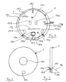
- Figure 1 shows a front view of an air intake cover 2 of an engine protection cover device according to a preferred embodiment of the present invention being installed into the intake opening of an air intake 10 of an exemplary engine 3.
- the air intake cover 1 comprises a disc shape, in particular round or oval, which is adapted in an inflated condition to the internal dimension of the intake opening of the air intake 10 of the specific engine 3 of an aircraft or spacecraft in order to be press fitted into the intake opening.
- the air intake cover 1 is preferably installed inside the skin area of the air intake 10 of the engine 3.
- the air intake cover 1 consists preferably of a PE, AST/ASA material, epoxy, carbon or any other suitable material which is resistant and inflatable.
- the air intake cover 1 comprises several handles 107 being positioned at predetermined areas of the air intake cover 1.
- at least two handles 107 are placed about at the horizontal centre line thereof symmetrical to each other. This improves the handling quality of the air intake cover 1. It is obvious to a person skilled in the art that the number and the position of handles can differ from the preferred embodiment as illustrated in Fig. 1 .
- the air intake cover 1 comprises a safety line 108 or safety pin strap which is attachable to a respective attachment means of the air intake 10. This advantageously aims to avoid a foreign object debris on the runway in case of an unintended deflation of the air intake cover 1 in case it is installed on the engine.
- the safety line 108 can be stored in a corresponding pocket 113 or the same during non-use of the air intake cover 1.
- the air intake cover 1 comprises a valve 109.
- the valve 109 is advantageously positioned at the front side of the air intake cover 1 in order not to come in contact with a surface of the engine and in order to provide an easy access for an inflation tube or inflation device.
- the valve 109 can be designed as a safety relief valve or an additional pressure relief means can be provided.
- a pressure relief threshold of about 5 to 7 psi, in particular of about 6,5 psi, is provided in order to protect the air intake cover 1 against bursting and the contacted surface of the engine 3 against damage. It is obvious to a skilled person that this threshold can be reduced or raised and can be adapted to the specific needs.
- the air intake cover 1 preferably comprises several distance positioning flaps 110, for example two distance positioning flaps 110 being positioned at about 4 and 8 o'clock positions as illustrated in Figure 1 .
- These distance positioning flaps 110 indicate the correct distance from for example a respective rivet line of the air intake 10 of the engine in order to address specific engineering requirements to avoid a damage to the nacelle structure due to the press fit configuration of the air intake cover 1.
- these flappers 110 can be conFigured as velcro fasteners in order to store the flappers 110 in an appropriate manner in case of non-use.
- the air intake cover 1 preferably comprises one or more specific information labellings 112.
- These information labellings 112 give information for example regarding the orientation of the intake cover 1, namely for example which part is the top of the air intake cover 1, for example by means of an arrow or a lettering, regarding the engine type to address the use of the right cover set for the correct engine type due to different sizing of different engines, regarding specific caution signs, for example "to be removed before flight", “sensor behind”, “safety pin stow location” or the same in order to avoid damages to the engine or specific engine parts, or regarding any other useful information.
- the air intake cover 1 is on the front side preferably designed in a signal colour, for example in red, in order to indicate to the operator that the air intake cover 1 is not part of the engine and has to be removed before the use of the engine.
- the air intake cover 1 of the present invention comprises an access opening 100 being airtight sealable by a corresponding hatch 101.
- the hatch 101 is lockable by a respective locking device in a closed position in which the hatch 101 closes the access opening 100 completely in an airtight sealed manner.
- the access opening 100 serves on the one hand for attaching a tube of a respective drying means (not shown), for example by means of bayonet lock of the same, in order to provide the possibility of connecting an air drying device to the access opening 100 of the air intake cover 1.
- the air drying device can be designed as an active humidity controller controlling the humidity content inside the engine 3 during storage, in particular during a long term storage.
- the access opening 100 of the air intake cover 1 aims to enable access to the inside of the engine for placing specific desiccant materials, in particular desiccant bags, to the inside of the engine or for replacing desiccant materials after use without the need of removing or shifting the air intake cover 1.
- the operation time is highly decreased advantageously.
- a mesh bag 105 is attached to the backside of the air intake cover 1 at the position of the access opening 100 in order to store the desiccant bags to be introduced via the access opening 100.
- the mesh bag 105 comprises a continuous and resistant bottom side 106 for carrying the desiccant bags without coming into direct contact with parts of the engine.
- the access opening 100, the corresponding hatch 101 and/or the mesh bag 105 can be designed in a round, oval, rectangular cross-sectional shape or the same. It is obvious to a person skilled in the art that the shapes and geometries of the access opening 100, the hatch 101 as well as of the mesh bag 105 and all other parts can differ from the embodiment illustrated in Figure 1 and can be designed in any other suitable shape and geometry.
- the air intake cover 1 further preferably comprises a friction protection means 104, for example being designed as a neoprene flap or the same, in order to protect the surface of the air intake seal against friction damage by the connected tube of an air drying device.
- the friction protection flap 104 can be stored in a respective pocket (not shown) or the same during non-use.
- the air intake cover 1 preferably further comprises an additional reinforcement layer or patch 111 at a predetermined location for protecting the air intake cover 1 against damages during contact with engine parts during the installation process.
- the additional patch or reinforcement layer 111 is preferably positioned in the centre of the air intake cover 1 at the backside thereof in order to avoid damages caused by the inlet cone of the engine 3 during the installation process. It is obvious to a person skilled in the art that further reinforcement layers or patches can be placed at any other suitable positions on the backside of the air intake cover 1.
- a suitable air intake cover 1 corresponding to the specific engine type, which has to be sealed, is selected and is placed in a deflated condition into the opening of the air intake 10 in a correct orientation and alignment.
- a pump is connected to the valve 109 and the air intake cover 1 is inflated at least partially in order to press fit the air intake cover 1 into the opening of the air intake 10.
- the distance positioning flaps 110 are used as a support to place the air intake cover 1 in the correct position in longitudinal direction of the engine 3.
- the operator uses the respective handles 107 accordingly.
- the access opening 100 is airtight sealed and the air intake cover 1 completely seals the air intake 10 in an airtight manner.
- desiccant bags or the same can be introduced via the access opening 100 to the mesh bag 105 at the inside of the engine 3.
- a respective air dryer in particular an active humidity controller, can be connected by means of a respective tube or pipe to the access opening 100 by means of a bayonet lock or the same.
- the engine protection cover device preferably additionally comprises an air exhaust cover 2 for airtight sealing the air exhaust 11 of the engine 3 in order to create an completely airtight sealed engine 3 and an engine being completely protected against foreign object debris.
- an air exhaust cover 2 for airtight sealing the air exhaust 11 of the engine 3 in order to create an completely airtight sealed engine 3 and an engine being completely protected against foreign object debris.
- the air exhaust cover 2 preferably exists of three cover parts, namely a C-ducts cover comprising two C-ducts cover parts 20a and 20b, an exhaust nozzle cover 30 and a nozzle end cap 40.
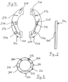
- the two C-ducts cover parts 20a and 20b are illustrated in Figure 4 in a front view, wherein Figure 5 illustrates a left side view thereof.
- the two C-ducts cover parts 20a and 20b can be designed as disconnected single parts or a specific connection line or flap might exist between them, for example in the lower area thereof.
- Analogue to the air intake cover 1, the two C-ducts cover parts 20a, 20b are made from an inflatable and resistant material like preferably a PE material, AST/ASA material, epoxy, carbon or any other suitable material which is resistant and inflatable.
- the two C-ducts cover parts 20a and 20b are formed with about a half ring shape being adapted to the C-ducts dimensions of the respective engine type being sealed, respectively. Respective rips or parts of the C-ducts of the engine 3 and interfaces thereof are taken into consideration for a suitable shape of the two C-ducts cover parts 20a, 20b such that a press fit into the two C-ducts of the engine 3 is provided.
- the two C-ducts cover parts 20a and 20b comprise several handles 207, wherein at least one handle 207 is positioned around the horizontal centre line and a further handle 207 is positioned in the upper area of each C-ducts cover part 20a and 20b, respectively, as illustrated in Figure 4 . It is obvious for a person skilled in the art that the number and positions of the handles can be adapted to the needs of the installation operator such that an installation can be conducted with the upmost quality and time efficiency.
- each C-ducts cover part 20a, 20b comprises a valve 209, wherein analogue to the air intake cover 1 the valve 209 can be formed as a safety relief valve or the same.
- a pressure relief threshold can be set to about 3 to 5 psi, in particular to about 3,5 psi. It is obvious to a person skilled in the art that this threshold can vary depending on the specific needs and in order to fulfil the requirements of specific seating performances.
- the respective valves 209 are positioned at lower front side positions, for example at 5 and 7 o'clock positions in order to avoid cosmetic damage to the engine surrounding area potentially caused by an inflation tube or the same.
- Each C-ducts cover part 20a, 20b further comprises one or more information labellings 212, wherein in this respect it is referred to the information labellings 112 of above described air intake cover 1, since the above-mentioned statements regarding the information labellings can be transferred to the present C-ducts cover parts 20a, 20b in an analogous manner.
- the above mentioned signal colour red can be used for all covers of the air exhaust cover 2, namely for the C-ducts cover parts 20a, 20b, for the exhaust nozzle cover 30 as well as for the nozzle end cap 40. Again it is referred to the explanations above in respect to the air intake cover 1.
- each C-ducts cover part 20a and 20b comprises a position marking 201, for example in form of a coloured marking line, indicating a proper installation position of each C-ducts cover part 20a, 20b.
- position markings 201 are provided for example on the outer circumference in a radial direction of each C-ducts cover part 20a, 20b.
- each C-ducts cover part 20a, 20b comprises a press fit design in particular in the upper and lower areas of the intersections of the two C-ducts cover parts 20a, 20b in order to provide a closed configuration and to avoid small gaps on these interface areas to the nacelle and to improve the engine preservation efficiency.
- an additional moisture barrier can be provided, in particular at the lower interface area of the two C-ducts cover parts 20a, 20b.
- the exhaust nozzle cover 30 is shaped in form of a ring and is adapted to the shape of a corresponding exhaust nozzle of a specific engine type being sealed.
- the exhaust nozzle cover 30 is also made from an inflatable material and comprises a valve 309, in particular at the front side of the exhaust nozzle cover 30.
- the exhaust nozzle cover 30 is made from an inflatable and resistant material like preferably a PE material, AST/ASA material, epoxy, carbon or any other suitable material which is resistant and inflatable. In this respect it is again referred to the explanations above in respect to the air intake cover 1 and the two C-ducts cover parts 20a, 20b.
- the exhaust nozzle cover 30 also comprises one or more information labellings 312. Again it is referred to the explanations above in respect to the information labellings 112 of air intake cover 1 as well as to the information labellings 212 of the C-ducts cover parts 20a, 20b.
- the exhaust nozzle cover 30 preferably comprises several handles 307, wherein two handles 307 are preferably positioned at 3 o'clock position and 9 o'clock positions as illustrated in Figure 6 , in order to improve the installation process as well as a safety connection which will be described further below.
- the exhaust nozzle cover 30 further comprises one or more distance positioning flaps 310, for example three positioning flaps at 3 o'clock, 6 o'clock and 9 o'clock positions, in order to indicate the maximum allowable positioning depth of the exhaust nozzle cover 30 to avoid that for example desiccant bags are being pushed into the engine during installation of the exhaust nozzle cover 30.
- one or more distance positioning flaps 310 for example three positioning flaps at 3 o'clock, 6 o'clock and 9 o'clock positions, in order to indicate the maximum allowable positioning depth of the exhaust nozzle cover 30 to avoid that for example desiccant bags are being pushed into the engine during installation of the exhaust nozzle cover 30.
- the exhaust nozzle cover 30 comprises a valve 309, wherein analogue to the air intake cover 1 the valve 309 can be formed as a safety relief valve or the same.
- a pressure relief threshold can be set to about 3 to 5 psi, in particular to about 3,5 psi.
- the air exhaust cover 2 further comprises a nozzle end cap 40, which is preferable made of a PVC material or the same.
- the nozzle end cap 40 is for example made as a tarpaulin cover being placed over the end nozzle of the engine 3.
- the nozzle end cap 40 has the shape of the respective end nozzle of the corresponding engine 3 being sealed.
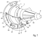
- Figure 7 illustrates an exemplary air exhaust 11 of an exemplary engine 3 being sealed with an air exhaust cover 2 existing of the two C-ducts cover parts 20a, 20b being press fitted into the corresponding C-ducts of the engine 3, the exhaust nozzle cover 30 being press fitted into the corresponding exhaust nozzle of the engine 3 and the nozzle end cap 40 being placed of the end nozzle of the corresponding engine 3.
- the exhaust nozzle cover 30 is connected to middle handles 207 of the C-ducts cover parts 20a, 20b by means of safety belts 308 in order to hold the exhaust nozzle cover 30 into a stable position.
- the nozzle end cap 40 is analogue secured by means of at least one safety belt 308 to the exhaust nozzle cover 30, wherein advantageously the middle handles 307 of the exhaust nozzle cover 30 are used for attaching the safety belt 408 of the nozzle end cap 40 to exhaust nozzle cover 30.
- the respective handles 207, 307 being positioned in the respective horizontal centre lines are used as an attachment means for an upmost stable attachment.
- the two C-ducts cover parts 20a, 20b are placed and aligned into the respective C-ducts of the engine 3 and inflated partly in order to press fit and to position them correctly. Afterwards, in case a predetermined position is achieved, the two C-ducts cover parts 20a, 20b are inflated to their full extend. Afterwards, the same is conducted with the exhaust nozzle cover 30 being inflated and press fitted into the corresponding exhaust nozzle of the engine 3. Afterwards, the safety belts 308 are attached to the respective handles 207 and 307 to secure the cover parts to each other. Finally, the nozzle end cap 40 is being placed over the end nozzle of the engine 3 and secured by means of the safety belt 408, also using the middle handles 307 of the exhaust nozzle cover 30.
Landscapes
- Engineering & Computer Science (AREA)
- Chemical & Material Sciences (AREA)
- Combustion & Propulsion (AREA)
- Mechanical Engineering (AREA)
- General Engineering & Computer Science (AREA)
- Aviation & Aerospace Engineering (AREA)
- Packaging Of Machine Parts And Wound Products (AREA)
- Filtering Of Dispersed Particles In Gases (AREA)
Priority Applications (3)
| Application Number | Priority Date | Filing Date | Title |
|---|---|---|---|
| EP23218106.5A EP4574680A1 (fr) | 2023-12-19 | 2023-12-19 | Dispositif de capot de protection de moteur pour assurer l'étanchéité à l'air d'un moteur d'un aéronef ou d'un engin spatial |
| CN202411859928.5A CN120175494A (zh) | 2023-12-19 | 2024-12-17 | 用于对航空器或航天器的发动机进行气密密封的发动机保护覆盖装置以及航空器或航天器 |
| US18/985,499 US12516625B2 (en) | 2023-12-19 | 2024-12-18 | Engine protection cover device for airtight sealing an engine of an aircraft or spacecraft |
Applications Claiming Priority (1)
| Application Number | Priority Date | Filing Date | Title |
|---|---|---|---|
| EP23218106.5A EP4574680A1 (fr) | 2023-12-19 | 2023-12-19 | Dispositif de capot de protection de moteur pour assurer l'étanchéité à l'air d'un moteur d'un aéronef ou d'un engin spatial |
Publications (1)
| Publication Number | Publication Date |
|---|---|
| EP4574680A1 true EP4574680A1 (fr) | 2025-06-25 |
Family
ID=89224575
Family Applications (1)
| Application Number | Title | Priority Date | Filing Date |
|---|---|---|---|
| EP23218106.5A Pending EP4574680A1 (fr) | 2023-12-19 | 2023-12-19 | Dispositif de capot de protection de moteur pour assurer l'étanchéité à l'air d'un moteur d'un aéronef ou d'un engin spatial |
Country Status (3)
| Country | Link |
|---|---|
| US (1) | US12516625B2 (fr) |
| EP (1) | EP4574680A1 (fr) |
| CN (1) | CN120175494A (fr) |
Families Citing this family (2)
| Publication number | Priority date | Publication date | Assignee | Title |
|---|---|---|---|---|
| US20250122814A1 (en) * | 2023-10-16 | 2025-04-17 | Serias-Lee, Llc | Aircraft Engine Opening Shield System with Installation Tool |
| US20250121955A1 (en) * | 2023-10-16 | 2025-04-17 | Serias-Lee, Llc | Aircraft Engine Opening Shield System with Installation Tool |
Citations (8)
| Publication number | Priority date | Publication date | Assignee | Title |
|---|---|---|---|---|
| US2744382A (en) * | 1954-06-21 | 1956-05-08 | Republic Aviat Corp | Removable inflatable protective closure for jet engine |
| US3000533A (en) * | 1959-04-24 | 1961-09-19 | William E Rockhill | Engine inlet plug |
| US5143321A (en) * | 1991-09-09 | 1992-09-01 | Thomas H. Jackson | Folding protective cover for turbo-engines |
| US20140008497A1 (en) * | 2012-07-09 | 2014-01-09 | Hamilton Sundstrand Corporation | Appartus and method for preventing gas turbine engine freezing |
| US20150089879A1 (en) * | 2012-02-08 | 2015-04-02 | The Boeing Company | Engine Cowl and Inlet Cover |
| CN105564667A (zh) * | 2016-02-05 | 2016-05-11 | 西安大鹏航空科技有限公司 | 一种飞机进气道封堵盖 |
| DE102019212436A1 (de) * | 2019-04-09 | 2020-10-15 | MTU Aero Engines AG | Verfahren zum enteisen eines mantelstromtriebwerks |
| WO2024083722A1 (fr) * | 2022-10-17 | 2024-04-25 | J.B. Roche (Mfg) Limited | Appareil à joint d'étanchéité de moteur d'aéronef |
Family Cites Families (10)
| Publication number | Priority date | Publication date | Assignee | Title |
|---|---|---|---|---|
| US3646980A (en) * | 1970-06-15 | 1972-03-07 | Peterson Products Of San Mateo | Jet engine cowl cover |
| FR2851787B1 (fr) * | 2003-02-28 | 2005-05-20 | Airbus France | Dispositif de protection d'une structure d'entree d'air d'un moteur a reaction |
| DE202012100112U1 (de) * | 2012-01-12 | 2012-02-27 | Klaus Rinck | Abdeckplane für Flugzeugtriebwerke |
| US8950701B2 (en) * | 2012-02-08 | 2015-02-10 | The Boeing Company | Engine cowl and inlet cover |
| US8651415B1 (en) * | 2012-02-08 | 2014-02-18 | The Boeing Company | Engine cowl and inlet cover |
| EP3565968B1 (fr) * | 2017-02-17 | 2020-11-04 | Siemens Gamesa Renewable Energy A/S | Procédé et couvercle destinés à couvrir une ouverture dans un élément d'une éolienne |
| WO2022032893A1 (fr) * | 2020-08-12 | 2022-02-17 | 田庆亮 | Couvercle de protection de moteur d'aéronef comportant un dispositif de gonflage |
| FR3126925B1 (fr) * | 2021-09-10 | 2025-04-18 | Airbus Operations Sas | Bâche de protection pour moteur de propulsion d’aéronef. |
| CA3183793A1 (fr) * | 2022-12-12 | 2024-06-12 | Protech Engine Solutions | Couvercle de protection pour moteurs d~aeronef |
| US20250121955A1 (en) * | 2023-10-16 | 2025-04-17 | Serias-Lee, Llc | Aircraft Engine Opening Shield System with Installation Tool |
-
2023
- 2023-12-19 EP EP23218106.5A patent/EP4574680A1/fr active Pending
-
2024
- 2024-12-17 CN CN202411859928.5A patent/CN120175494A/zh active Pending
- 2024-12-18 US US18/985,499 patent/US12516625B2/en active Active
Patent Citations (8)
| Publication number | Priority date | Publication date | Assignee | Title |
|---|---|---|---|---|
| US2744382A (en) * | 1954-06-21 | 1956-05-08 | Republic Aviat Corp | Removable inflatable protective closure for jet engine |
| US3000533A (en) * | 1959-04-24 | 1961-09-19 | William E Rockhill | Engine inlet plug |
| US5143321A (en) * | 1991-09-09 | 1992-09-01 | Thomas H. Jackson | Folding protective cover for turbo-engines |
| US20150089879A1 (en) * | 2012-02-08 | 2015-04-02 | The Boeing Company | Engine Cowl and Inlet Cover |
| US20140008497A1 (en) * | 2012-07-09 | 2014-01-09 | Hamilton Sundstrand Corporation | Appartus and method for preventing gas turbine engine freezing |
| CN105564667A (zh) * | 2016-02-05 | 2016-05-11 | 西安大鹏航空科技有限公司 | 一种飞机进气道封堵盖 |
| DE102019212436A1 (de) * | 2019-04-09 | 2020-10-15 | MTU Aero Engines AG | Verfahren zum enteisen eines mantelstromtriebwerks |
| WO2024083722A1 (fr) * | 2022-10-17 | 2024-04-25 | J.B. Roche (Mfg) Limited | Appareil à joint d'étanchéité de moteur d'aéronef |
Also Published As
| Publication number | Publication date |
|---|---|
| CN120175494A (zh) | 2025-06-20 |
| US20250198329A1 (en) | 2025-06-19 |
| US12516625B2 (en) | 2026-01-06 |
Similar Documents
| Publication | Publication Date | Title |
|---|---|---|
| US12516625B2 (en) | Engine protection cover device for airtight sealing an engine of an aircraft or spacecraft | |
| US5242206A (en) | Automotive hail blanket | |
| US6053348A (en) | Pivotable and sealable cap assembly for opening in a large container | |
| US5082244A (en) | Cargo air bag inflation valve and inflator combination | |
| US4073389A (en) | Dunnage bag fill valve device with integral combination baffle, plug retainer, and bladder separator | |
| US7178867B2 (en) | Secure life jacket container | |
| US20030213518A1 (en) | Air bag inflation/ deflation system | |
| US20070175378A1 (en) | Floatation system including life raft | |
| CA2622768A1 (fr) | Ameliorations de dispositifs d'etancheite | |
| US20090179167A1 (en) | Inflation/deflation adaptor assembly for inflating and deflating inflatable cargo dunnage bags | |
| US6644592B2 (en) | Floatation system | |
| US8235632B2 (en) | Cargo bag valve deflector | |
| US4469152A (en) | Dust-tight hatch closure assembly | |
| WO2006046038A3 (fr) | Procede et systeme ameliores | |
| EP1063176B1 (fr) | Fermeture pour récipient comportant une soupape à air | |
| US6182826B1 (en) | Inflatable protective cover for golf club bags | |
| CN209022740U (zh) | 一种汽车全封闭式充气防水装置 | |
| US10370168B1 (en) | Multi-chamber packaging devices | |
| JP2009139374A (ja) | 加圧能力を有する産業用梱包 | |
| CN1080397C (zh) | 一用于包袋、口袋或类似容器的充气阀 | |
| CN212981267U (zh) | 一种液态危险废物储存罐 | |
| JPH0155440B2 (fr) | ||
| US20170282653A1 (en) | Container for tire-balancing material | |
| EP0743021A3 (fr) | Dispositif de protection d'une personne transportée sur un véhicule ou un animal de transport | |
| US20250128867A1 (en) | Inflatable cover for transporting goods |
Legal Events
| Date | Code | Title | Description |
|---|---|---|---|
| PUAI | Public reference made under article 153(3) epc to a published international application that has entered the european phase |
Free format text: ORIGINAL CODE: 0009012 |
|
| STAA | Information on the status of an ep patent application or granted ep patent |
Free format text: STATUS: THE APPLICATION HAS BEEN PUBLISHED |
|
| AK | Designated contracting states |
Kind code of ref document: A1 Designated state(s): AL AT BE BG CH CY CZ DE DK EE ES FI FR GB GR HR HU IE IS IT LI LT LU LV MC ME MK MT NL NO PL PT RO RS SE SI SK SM TR |
|
| STAA | Information on the status of an ep patent application or granted ep patent |
Free format text: STATUS: REQUEST FOR EXAMINATION WAS MADE |
|
| 17P | Request for examination filed |
Effective date: 20251121 |