EP4574683A1 - Objet stabilise dans un espace flottant et procede de reglage de l'orientation d'un objet en surpesanteur ou en cas libre - Google Patents
Objet stabilise dans un espace flottant et procede de reglage de l'orientation d'un objet en surpesanteur ou en cas libre Download PDFInfo
- Publication number
- EP4574683A1 EP4574683A1 EP24203930.3A EP24203930A EP4574683A1 EP 4574683 A1 EP4574683 A1 EP 4574683A1 EP 24203930 A EP24203930 A EP 24203930A EP 4574683 A1 EP4574683 A1 EP 4574683A1
- Authority
- EP
- European Patent Office
- Prior art keywords
- reaction wheel
- gravity
- center
- wheel arrangement
- rotation
- Prior art date
- Legal status (The legal status is an assumption and is not a legal conclusion. Google has not performed a legal analysis and makes no representation as to the accuracy of the status listed.)
- Pending
Links
Images


Classifications
-
- B—PERFORMING OPERATIONS; TRANSPORTING
- B64—AIRCRAFT; AVIATION; COSMONAUTICS
- B64G—COSMONAUTICS; VEHICLES OR EQUIPMENT THEREFOR
- B64G1/00—Cosmonautic vehicles
- B64G1/22—Parts of, or equipment specially adapted for fitting in or to, cosmonautic vehicles
- B64G1/24—Guiding or controlling apparatus, e.g. for attitude control
- B64G1/242—Orbits and trajectories
-
- B—PERFORMING OPERATIONS; TRANSPORTING
- B64—AIRCRAFT; AVIATION; COSMONAUTICS
- B64G—COSMONAUTICS; VEHICLES OR EQUIPMENT THEREFOR
- B64G1/00—Cosmonautic vehicles
- B64G1/22—Parts of, or equipment specially adapted for fitting in or to, cosmonautic vehicles
- B64G1/40—Arrangements or adaptations of propulsion systems
- B64G1/409—Unconventional spacecraft propulsion systems
Definitions
- the invention relates to an object that can be stabilized while floating freely in space, in particular a space object, according to the preamble of patent claim 1. It further relates to a method for controlling the attitude of an object having a center of gravity in weightlessness or in free fall according to claim 13.
- the invention thus relates to an object that can be stabilized in a space, for example in outer space or in free fall under the influence of gravity, while floating freely, and that is coupled to an external object extension device (2) that can move independently in space.
- an object can, for example, be a space station to which a robot arm is coupled externally as an object extension device.
- Such an object can also, for example, be a satellite to be maintained or repaired, to which a robot satellite is coupled as a service satellite.
- the invention relates to a method for controlling the orientation of objects in weightlessness (for example in space) or in free fall in a gravitational field by means of an attitude determination and control system, and to the mechanical structure of a device suitable for carrying out this method, having an extended reaction wheel assembly, a so-called Extended Reaction Wheel Assembly (ERW).
- ERW Extended Reaction Wheel Assembly
- Attitude control systems are implemented in a variety of technical ways.
- Reaction wheels active momentum gyroscopes, or thrusters can be used.
- at least one reaction wheel is typically used for one spatial axis to control its orientation.
- the reaction wheels are rigidly connected to the object and form devices for exchanging angular momentum. These devices are used to control the orientation of space objects and typically feature actuated, i.e., drive-driven, rotating disks.
- An object within the meaning of the present application can be, for example, a satellite, a spacecraft, a space station, or even a non-technological space object, such as a rocket or rocket stage, a space debris object, or even an asteroid.
- the invention is not limited to the aforementioned space objects; it can also be applied to "terrestrial" flying objects, for example, when they are in free fall within the gravitational field of a celestial body.
- the rotational speed of such reaction wheels is proportional to the orientation of the object around the rotational axis of a respective rotational wheel.
- the maximum rotational speed and rotational acceleration of a rotational wheel are subject to technical and physical limitations, for example, due to the load limits of the rotational bearings and the centrifugal force resistance of the rotational wheel, as well as the motor power of a drive for the rotational wheel. Accordingly, the change in the orientation of the object is also subject to corresponding limitations. Changes or corrections to the Orientation of such an object can therefore only be performed to a limited extent, namely as frequently and as intensively as necessary until the rotation wheel has reached its maximum rotation speed.
- attitude control thrusters Changing the rotation speed of a reaction wheel for a spatial axis, for example, to reduce the rotation speed of the rotation wheel again, is usually accompanied by an undesirable change in the object's orientation and must therefore be compensated for by another attitude control system, such as attitude control thrusters.
- attitude control thrusters The major disadvantage of thrusters, however, is the limited fuel supply on the object and thus the limited service life of an attitude control system.
- the object of the present invention is to provide an object which can be stabilized in a freely suspended space and which is coupled to an external object extension device which can be moved independently in space, with improved attitude control properties and an improved method for the attitude control of such a unit consisting of an object and an object extension device, which function independently of fuel supplies even over a long period of time.
- An object that can be stabilized while floating freely in space is provided with a first position control device on the object side for controlling the position of the object having a center of gravity in weightlessness or in free fall, wherein the object is connected to an external device that can be moved independently in space.
- object extension device which in turn is provided with a second position control device movable relative to the object.
- Movements of an object extension device coupled to such an object are conventionally compensated by the object-side attitude control device, which can quickly reach its limits.
- the inventors have recognized that a second attitude control device additionally provided on the object extension device can not only relieve the load on the object-side, first attitude control device, but, in conjunction with the first attitude control device, can even improve its attitude control properties.
- the second attitude control device has at least one extended reaction wheel arrangement coupled to the object, which in turn has a center of gravity.
- a reaction wheel arrangement is a proven attitude control means.
- the extended reaction wheel arrangement is provided with at least one reaction wheel that can be rotated about a rotation axis by means of a rotation drive.
- the rotation axis of the reaction wheel can be displaced relative to the object's center of gravity by means of at least one actuator.
- the rotary drive and the at least one actuator can be controlled by a control device.
- a particularly preferred implementation of the invention is characterized in that the object is a space object.
- the object extension device comprises or is formed by a robot arm that can be moved in space.
- the at least one reaction wheel is attached to the object via a lever mechanism, wherein the reaction wheel is provided with the rotation drive and the lever mechanism is provided with the at least one actuator which is designed to subject at least one lever arm of the lever mechanism to a pivoting movement about an associated pivot axis in order to thus carry out the translational movement of the center of gravity of the reaction wheel arrangement along the circular path around the object center of gravity.
- the reaction wheel is mounted at the free end of a lever arm of the lever mechanism so that it can rotate about its rotation wheel axis.
- the lever mechanism has two or more lever arms, each of which can be pivoted about an associated pivot axis by means of an associated actuator.
- a lever mechanism comprising two lever arms coupled in series in a hinged manner is particularly advantageous, the joints of which each have an actuator and whose pivot axes run parallel to one another.
- the pivoting movement effected by the respective actuator in the respective lever joint is advantageously controlled by the control device in such a way that the The center of gravity of the extended reaction wheel arrangement performs a linear translational movement away from the object center of gravity or towards the object center of gravity in the first and third steps.
- the pivot axes of the lever arms run parallel to each other and parallel to the rotation axis of the reaction wheel.
- three reaction wheel arrangements are provided in an object, wherein the pivot and rotation axes of a first rotation wheel arrangement are orthogonal to the pivot and rotation axes of a second rotation wheel arrangement, wherein the pivot and rotation axes of the second rotation wheel arrangement are orthogonal to the pivot and rotation axes of a third rotation wheel arrangement, and wherein the pivot and rotation axes of the third rotation wheel arrangement are orthogonal to the pivot and rotation axes of the first rotation wheel arrangement.
- the rotational speed of a respective reaction wheel can, for example, be desaturated, i.e. brought to zero, without inducing a change in the orientation of the object.
- the actuator-controlled movement of the center of gravity of the extended reaction wheel arrangement on a radially outer path, in particular a circular path, around the object's center of gravity according to the second step induces, in principle, an angular momentum on the object, but this is compensated by the synchronous deceleration of the rotational speed of the reaction wheel.
- the rotation speed of the reaction wheel has reached the specified target value, for example zero, the movement of the reaction wheel on the path around the object's center of gravity is stopped.
- the reaction wheel is then moved translationally toward the object's center of gravity, for example, to restore the original radial distance.
- the rotational speed of the reaction wheel is changed, for example, reduced, without inducing any angular momentum in the object; the object therefore retains its position in space unchanged.
- the changed rotational speed of the reaction wheel forms a target variable according to which the translational movement of the center of gravity of the extended reaction wheel arrangement along the path, in particular the circular path, around the object's center of gravity is determined in the control device.
- a computer provided in or associated with the control device calculates, based on the target value of the desired rotational speed, the required trajectory of the reaction wheel when performing steps one to three, as well as the speed of the radial movements and the movement of the center of gravity of the extended reaction wheel arrangement along the circular path, and provides corresponding control signals for the actuators and the rotation drive.
- the changed rotational speed of the reaction wheel i.e., the target value of the rotational speed of the reaction wheel, is zero. This allows the full range of the position control capability of the reaction wheel arrangement to be restored.
- the target variable can also take any positive or negative value if, for example, an external impulse is expected to be applied to the object, for example when a spacecraft docks to a space station in order to achieve a permanent change in the orientation of the Object (e.g., the space station) after the docking maneuver.
- the method according to the invention can even be carried out synchronously during the docking maneuver in order to minimize or even prevent any change in the position of the object during docking.
- the core of the invention relating to the method thus consists in a method for controlling the position of an object having a center of gravity in weightlessness or in free fall by means of at least one extended reaction wheel arrangement coupled to the object and is characterized in that in a first step the at least one actuator moves the distance of the center of gravity of the extended reaction wheel arrangement in a first translational movement along a straight line emanating from the object center of gravity, wherein the rotational speed of the reaction wheel does not change; that in a second step the at least one actuator moves the center of gravity of the extended reaction wheel arrangement on a circular path around the object center of gravity, wherein at the same time the rotational drive changes the rotational speed of the reaction wheel such that the vectorial sum of the angular momentum of the reaction wheel rotating about the reaction wheel axis and the angular momentum of the extended reaction wheel arrangement moving about the object center of gravity axis along the circular path is constant, and that in a third step the at least one actuator moves the center of gravity of the extended reaction wheel arrangement in a second translational movement along
- Fig. 1 shows a schematic diagram of a device according to the invention for controlling the attitude of an object formed by a satellite 1 in space or in an orbit under the influence of weightlessness.
- the reaction wheel 20 of the reaction wheel arrangement 2' is rotatable about a rotation wheel axis 20' by means of a rotation drive 21 and is rotatably mounted on a first lever arm 23 of the lever mechanism 24 by means of a rotation bearing 22.
- the first lever arm 23 is mounted on a second lever arm 27 of the lever mechanism 24 by means of a first pivot bearing 25 and is pivotably mounted about a first pivot axis 25'.
- a first actuator 26 is provided in the region of the first pivot bearing 25 and is designed to pivot the first lever arm 23 relative to the second lever arm 27.
- the second lever arm 27 is pivotably mounted on the structure 10 of the satellite about a second pivot axis 28' by means of a second pivot bearing 28.
- a second actuator 29 is provided in the region of the second pivot bearing 28 and is designed to pivot the second lever arm 27 relative to the structure 10 of the satellite 1.
- the rotary drive 21, the first actuator 26 and the second actuator 29 are supplied with control signals by a control device 3, as shown in Fig. 1 symbolically shown by thin lines to carry out the method according to the invention.
- Fig. 1 schematically shown are the center of mass of the satellite 1, designated as the object center of mass So, with its object center of mass axis 13 and the center of mass of the reaction wheel arrangement 2', designated as the center of mass S ERW , as well as a circular path 4, on which the center of mass S ERW of the reaction wheel arrangement 2' moves according to the method of the invention, as described below with reference to the Fig. 2 will be explained later.
- the first pivot axis 25', the second pivot axis 28' and the rotation wheel axis 20' run parallel to each other and to the object center of gravity axis 13 and extend in Fig. 1 perpendicular to the plane of the drawing. Consequently, a pivoting movement of the lever arms 23 occurs and 27 of the lever mechanism 24 in one plane, namely in the plane of the Fig. 1 .
- Fig. 2 is a schematic representation of the movement profile that the center of gravity S ERW of the reaction wheel arrangement 2' travels through when the method of the invention is carried out.
- the first actuator 26 and the second actuator 29 are actuated synchronously such that the first lever arm 23 and the second lever arm 27 are pivoted such that the center of gravity S ERW of the extended reaction wheel arrangement 2' moves away from the object center of gravity So in a first translational movement along a straight line A emanating from the object center of gravity So, whereby the distance of the center of gravity S ERW from the object center of gravity So increases, wherein the rotational speed of the reaction wheel 20 does not change and consequently the angular momenta around the center of gravity S ERW of the extended reaction wheel arrangement 2' and around the object center of gravity So compensate each other, i.e. no angular momentum is induced in the object formed by the satellite 1.
- the two actuators 26, 29 are supplied with signals by the control device 3 such that they move the reaction wheel arrangement 2' such that the center of gravity S ERW of the extended reaction wheel arrangement 2' moves along a curved trajectory B on a circular path 4 around the object center of gravity axis 13 of the object center of gravity So.
- the rotation drive 21 is supplied with signals by the control device 3 such that the rotational speed of the reaction wheel 20 is gradually reduced.
- the sum of the angular momentum of the reaction wheel 20 rotating around the rotation wheel axis 20' and the angular momentum of the extended reaction wheel arrangement 2' moving around the object center of gravity axis along the circular path 4 remains constant.
- the rotational speed of the reaction wheel 20 is reduced—preferably to zero—by appropriately applying force to the reaction wheel drive 21, without inducing an additional angular momentum on the object 1; the object 1 thus maintains its orientation in space.
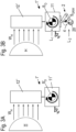
- Fig. 3A and 3B show an application for desaturating the reaction wheel while maintaining a constant orientation of the object during the execution of the trajectory optimized according to the invention.
- “Desaturation” refers to bringing the rotational speed of the reaction wheel 20 to zero.
- Fig. 3A shows a conventionally constructed satellite arrangement 1' with a satellite body 11' and a solar panel 12' extended therefrom, which is illuminated by the sun H.
- the radiation pressure of the solar radiation W H emanating from the sun H causes the satellite arrangement 1' to gradually rotate around its center of gravity So away from its desired orientation.
- the satellite is equipped with a reaction wheel arrangement 2' according to the invention.
- the reaction wheel 20 is required to compensate for the orientation disturbance caused by the sun's radiation pressure.
- the rotation speed of the reaction wheel 20 must be continuously changed in one direction. This inevitably leads to reaching the technical limits of the reaction wheel arrangement 2' (maximum rotation speed) at some point. This problem of reaching these limits is counteracted by the method according to the invention, since the reaction wheel can be desaturated from time to time.
- FIG. 4 shows another application of the method and device according to the invention, namely a targeted increase in the rotational speed of the reaction wheel 20 for the purpose of preparing for planned events.
- a space station 1" with a solar panel 12, a docking module 14 provided with a docking port 15, and a lounge module 16 is equipped with the reaction wheel arrangement 2' according to the invention.
- a space transporter 5 moves towards the space station.
- the rotational speed of space station 1" is zero at the beginning. Docking of space transporter 5 at docking port 15 is carried out by means of a docking interface 50. At the moment of docking, based on the law of conservation of momentum, a rotational speed around the overall center of gravity So would be induced on space station 1".
- this induced rotational velocity would be compensated by rotating wheels, which start at a rotational velocity dependent on previous maneuvers. Once a rotating wheel has reached its maximum speed, it can no longer contribute to compensating the induced angular momentum, and compensation must be performed by attitude control thrusters.
- the rotational speed of the reaction wheel can be changed independently of the orientation of the object, i.e. the space station 1". Accordingly, the rotational speed of the respective reaction wheel can be set before docking in the opposite direction of rotation to the direction of rotation required after docking in order to stabilize the space station 1". Due to this opposite initial direction of rotation, the The reaction wheel in question can generate torque in the desired direction for a longer period of time than, for example, a reaction wheel that initially has a rotational speed of zero. This has the advantage that either the object, i.e., the space station, can be stabilized more quickly, or that the reaction wheels used can be smaller.
- the mechanical structure of the device according to the invention thus comprises a chain of at least one actuator 26, 29 and at least one reaction wheel 20, wherein the reaction wheel 20 can be mounted either at the end of a serial chain or decentrally on or at the object 1.
- the method according to the invention is controlled by a control device 3 with a computer on which, for example, a program with an algorithm for the coordinated control of the actuators 26, 29 and the reaction wheel 20 runs with the aim of achieving a desired final rotation speed of the reaction wheel 20.
- a control device 3 with a computer on which, for example, a program with an algorithm for the coordinated control of the actuators 26, 29 and the reaction wheel 20 runs with the aim of achieving a desired final rotation speed of the reaction wheel 20.
- the control of the actuators 26, 29 takes place in a manner that changes the overall orientation of the object 1 only in a desired manner by observing the conservation of angular momentum.
- the trajectory of the extended reaction wheel arrangement 2' is determined, for example, by an optimization calculation based on equation (4). This takes advantage of the fact that the momentum h is constant due to momentum conservation. Accordingly, V_a and V_r are optimized such that V_s follows a desired setpoint trajectory (e.g., remains constant at zero to avoid inducing net rotation). As a further task in the optimization calculation, a cost function is formulated that causes the rotational speed of the reaction wheels 20 to follow a setpoint trajectory (e.g., is zero to desaturate the reaction wheel).
- the device according to the invention may also take on embodiments other than those described above.
- the device may have features that represent a combination of the respective individual features of the claims.
Landscapes
- Engineering & Computer Science (AREA)
- Remote Sensing (AREA)
- Chemical & Material Sciences (AREA)
- Combustion & Propulsion (AREA)
- Radar, Positioning & Navigation (AREA)
- Aviation & Aerospace Engineering (AREA)
- Control Of Position, Course, Altitude, Or Attitude Of Moving Bodies (AREA)
Applications Claiming Priority (1)
| Application Number | Priority Date | Filing Date | Title |
|---|---|---|---|
| DE102023136423.5A DE102023136423B4 (de) | 2023-12-21 | 2023-12-21 | In einem Raum freischwebend stabilisierbares Objekt und Verfahren zur Lageregelung eines Objekts in der Schwerelosigkeit oder im freien Fall |
Publications (1)
| Publication Number | Publication Date |
|---|---|
| EP4574683A1 true EP4574683A1 (fr) | 2025-06-25 |
Family
ID=92966913
Family Applications (1)
| Application Number | Title | Priority Date | Filing Date |
|---|---|---|---|
| EP24203930.3A Pending EP4574683A1 (fr) | 2023-12-21 | 2024-10-01 | Objet stabilise dans un espace flottant et procede de reglage de l'orientation d'un objet en surpesanteur ou en cas libre |
Country Status (2)
| Country | Link |
|---|---|
| EP (1) | EP4574683A1 (fr) |
| DE (1) | DE102023136423B4 (fr) |
Citations (4)
| Publication number | Priority date | Publication date | Assignee | Title |
|---|---|---|---|---|
| JPH09101822A (ja) * | 1995-10-06 | 1997-04-15 | Fujitsu Ltd | 姿勢安定化装置 |
| US20050077425A1 (en) * | 2003-10-10 | 2005-04-14 | Raymond Payette | Thruster for propelling and directing a vehicle without interacting with environment and method for making the same |
| DE102007041994B4 (de) * | 2007-09-04 | 2009-08-13 | Schepelmann, Jürgen | Mechanismus zum Ausschleudern einer Stoßmasse zur Ablenkung eines störenden Satelliten auf eine tolerierbare Bahn durch Kollision |
| CN113829360A (zh) * | 2021-08-30 | 2021-12-24 | 浙江万里学院 | 弹跳机器人及其动量轮组件和姿态控制方法 |
-
2023
- 2023-12-21 DE DE102023136423.5A patent/DE102023136423B4/de active Active
-
2024
- 2024-10-01 EP EP24203930.3A patent/EP4574683A1/fr active Pending
Patent Citations (4)
| Publication number | Priority date | Publication date | Assignee | Title |
|---|---|---|---|---|
| JPH09101822A (ja) * | 1995-10-06 | 1997-04-15 | Fujitsu Ltd | 姿勢安定化装置 |
| US20050077425A1 (en) * | 2003-10-10 | 2005-04-14 | Raymond Payette | Thruster for propelling and directing a vehicle without interacting with environment and method for making the same |
| DE102007041994B4 (de) * | 2007-09-04 | 2009-08-13 | Schepelmann, Jürgen | Mechanismus zum Ausschleudern einer Stoßmasse zur Ablenkung eines störenden Satelliten auf eine tolerierbare Bahn durch Kollision |
| CN113829360A (zh) * | 2021-08-30 | 2021-12-24 | 浙江万里学院 | 弹跳机器人及其动量轮组件和姿态控制方法 |
Also Published As
| Publication number | Publication date |
|---|---|
| DE102023136423B4 (de) | 2025-10-16 |
| DE102023136423A1 (de) | 2025-06-26 |
Similar Documents
| Publication | Publication Date | Title |
|---|---|---|
| DE69700728T2 (de) | Verfahren und Vorrichtung zur Lageerhaltung eines Satelliten | |
| DE69010286T2 (de) | Satellit und Verfahren, um einen Satelliten in eine Umlaufbahn mit Hilfe der Schwerkraft zu bringen. | |
| DE69316970T2 (de) | Raumfahrzeug mit Ost/Westorbitlageregelung während eines Nord- oder Südpositionshaltemanövers | |
| DE69926854T2 (de) | Methode und Vorrichtung zur Lageregelung eines Satelliten | |
| DE69412211T2 (de) | Verfahren zur Lageerhaltung eines Satelliten | |
| DE69111437T2 (de) | Verfahren zur steuerung des nickwinkels eines satelliten mittels sonnenwinddruck und satellit zur durchführung desselben. | |
| DE69022203T2 (de) | Verfahren zur Steuerung der Neigung eines Satelliten bezüglich der Roll- und der Gierachse. | |
| DE69616951T2 (de) | Verfahren und Vorrichtung zur Lageerhaltung eines durch Nicksrotation versetzen Satelliten | |
| DE69716499T2 (de) | System und Verfahren um mit Triebwerken mit hohen spezifischen Impulsen versehen ein Raumfahrzeug in eine Umlaufbahn zu bringen | |
| DE68910501T2 (de) | Vorrichtung und verfahren zur änderung des orbits eines künstlichen satelliten. | |
| DE2642061C2 (de) | Lageregelungs- und Bahnänderungsverfahren für einen dreiachsenstabilisierbaren Satelliten, insbesondere für einen geostationären Satelliten und Einrichtung zur Durchführung des Verfahrens | |
| DE69905005T2 (de) | Verfahren und vorrichtung zur ruderkontrolle in einem luft- oder wasserfahrzeug mittels einer betätigung in einer ebene | |
| DE69315129T2 (de) | Verfahren und Vorrichtung zur Momentausgleichung eines Satelliten | |
| DE69105048T2 (de) | Methode zur Ausrichtung der Lage eines zur Erde ausgerichteten Raumflugkörpers. | |
| DE69730110T2 (de) | Verfahren um Satelliten in nicht-koplanare Umlaufbahnen unter Verwendung von sehr excentrischen Umlaufbahnen und atmosphärischem Strömungswiderstand gleichzeitig zu bringen | |
| DE69206204T2 (de) | Verfahren und Vorrichtung zur kontinuierlichen und unidirektionalen Roll- und Gierlagesteuerung eines Satelliten. | |
| DE3136320C2 (de) | Verfahren und Vorrichtung zur Unterdrückung des Außenlast-Tragflügel-Flatterns von Flugzeugen | |
| EP1108647B1 (fr) | Système de contrôle d'attitude et d'arrondissement d'un parachute pour largage et méthode d'opération | |
| DE2604005A1 (de) | Einrichtung zur beeinflussung der position und lage eines satelliten | |
| DE69309624T2 (de) | Verfahren zur Immobilisierung von Treibstoff | |
| DE2931612C3 (de) | Verfahren und System zur Lageausrichtung eines drallstabilisierten Raumfahrzeugs | |
| DE102018211292B4 (de) | Lageregelungsvorrichtung für einen Satelliten und Verfahren zum Lageregeln eines Satelliten | |
| EP1094002A2 (fr) | Système et méthode de contrôle d'un satellite | |
| DE3918832A1 (de) | Fluglageregelanordnung | |
| DE3420441C2 (fr) |
Legal Events
| Date | Code | Title | Description |
|---|---|---|---|
| PUAI | Public reference made under article 153(3) epc to a published international application that has entered the european phase |
Free format text: ORIGINAL CODE: 0009012 |
|
| STAA | Information on the status of an ep patent application or granted ep patent |
Free format text: STATUS: THE APPLICATION HAS BEEN PUBLISHED |
|
| AK | Designated contracting states |
Kind code of ref document: A1 Designated state(s): AL AT BE BG CH CY CZ DE DK EE ES FI FR GB GR HR HU IE IS IT LI LT LU LV MC ME MK MT NL NO PL PT RO RS SE SI SK SM TR |
|
| STAA | Information on the status of an ep patent application or granted ep patent |
Free format text: STATUS: REQUEST FOR EXAMINATION WAS MADE |
|
| 17P | Request for examination filed |
Effective date: 20251204 |
|
| STAA | Information on the status of an ep patent application or granted ep patent |
Free format text: STATUS: EXAMINATION IS IN PROGRESS |
|
| 17Q | First examination report despatched |
Effective date: 20260327 |