EP4574745A1 - Manipulationssicherer flüssigkeitsabgabehahn - Google Patents
Manipulationssicherer flüssigkeitsabgabehahn Download PDFInfo
- Publication number
- EP4574745A1 EP4574745A1 EP23220842.1A EP23220842A EP4574745A1 EP 4574745 A1 EP4574745 A1 EP 4574745A1 EP 23220842 A EP23220842 A EP 23220842A EP 4574745 A1 EP4574745 A1 EP 4574745A1
- Authority
- EP
- European Patent Office
- Prior art keywords
- tap
- tamper evident
- cap
- configuration
- driving member
- Prior art date
- Legal status (The legal status is an assumption and is not a legal conclusion. Google has not performed a legal analysis and makes no representation as to the accuracy of the status listed.)
- Pending
Links
Images





Classifications
-
- B—PERFORMING OPERATIONS; TRANSPORTING
- B67—OPENING, CLOSING OR CLEANING BOTTLES, JARS OR SIMILAR CONTAINERS; LIQUID HANDLING
- B67D—DISPENSING, DELIVERING OR TRANSFERRING LIQUIDS, NOT OTHERWISE PROVIDED FOR
- B67D3/00—Apparatus or devices for controlling flow of liquids under gravity from storage containers for dispensing purposes
- B67D3/04—Liquid-dispensing taps or cocks adapted to seal and open tapping holes of casks, e.g. for beer
- B67D3/043—Liquid-dispensing taps or cocks adapted to seal and open tapping holes of casks, e.g. for beer with a closing element having a linear movement, in a direction perpendicular to the seat
Definitions
- the present invention relates to a tamper-evident tap for dispensing liquid from a container, and specifically from a container of the type "Bag-in-Box" (also referred to as BiB).
- tamper-evident taps for dispensing liquid from a respective container are known.
- These taps comprise driving members having wings that can be actuated by a user.
- a lifting force is applied to bias the driving member from a lower position to an upper position, mainly by the index and middle fingers placed on the wings and by the thumb placed on an upper surface of the tap in a position opposite to the lifting force.
- the driving member moves axially within the cap between the upper and lower positions in order to open the tap.
- the driving member is coupled to a valve, or a membrane, and is configured to bias such valve from a closed configuration to an open configuration.
- the valve In the closed configuration, the valve is configured to seal the tap and prevent the dispensing of liquids from the container.
- EP 4069628 A1 discloses a tamper-preventing tap for dispensing liquids and with an automatic opening that complies with these directives.
- the disclosed tap comprises a driving element with protruding wings coupled to an internal elastic valve and adapted to move axially inside a cap of the tap. It also comprises integrated sealing elements configured to be broken by the driving element when the tap is first opened.
- the known taps have the disadvantage of not fixing such tamper-evident element to the tap, which can lead to its detachment during transport, making it difficult to recycle it and increasing the risk of individual plastic elements entering the environment.
- the tap disclosed in EP 4069628 A1 requires the tamper-evident element (namely the sealing elements) to be broken by the drive element because of the lifting force applied. In this way, there is a risk that the breakage of the sealing elements will disperse a piece or fragment of plastic into the environment. Additionally, the fragments from the broken sealing elements may be introduced into the internal part of the cap and damage the elastic membrane, thereby compromising its sealing function. Worse still, a fragment may be introduced into the liquid as it is dispensed from the container, potentially harming the user.
- object of the present invention is providing a tamper-evident tap for dispensing liquid capable of overcoming the aforementioned prior art drawbacks.
- the tap of the present invention comprises a containing body connectable to a container, a valve element located therein, a hollow cap connected to the containing body and a driving member operatively connected to the valve element and adapted to move within the cap from a lower position to an upper position to bias the valve element from a closed configuration to an open configuration.
- the cap comprises tamper evident elements configured to cooperate with the driving member in order to be moved towards the cap upon the movement of the driving member to the upper position on first opening.
- the tamper evident elements give visual evidence of first opening of the tap, thus revealing any tampering attempts.
- the tamper evident elements are also retained within the cap, so that they do not interfere with further operations of the driving member in opening and closing the tap.
- the tap 1 refers to a tamper-evident liquid-dispensing tap.
- the tap 1 of the present invention is adapted for the dispensing of liquid from a container, not shown in the attached figures, specifically for a container of the type "Bag-in-Box" (or BiB container).
- the tap 1 comprises a containing body 2 having a dispensing opening 2a delimited by an internal surface 2b.
- the containing body 2 comprises a connecting portion 20 configured to be connected to the container.
- the dispensing opening 2a allows the dispensing of liquids from the container to the outside the tap 1.
- the containing body 2 is made of plastic material.
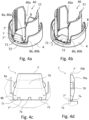
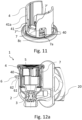
- the tap 1 also comprises a valve element 3 ( Figs. 3a, 3b , 5a, 6a , 7a, 8 , 12a-12c ) located inside the containing body 2 and configured to engage the containing body 2, and specifically the internal surface 2b of the containing body 2, to close the dispensing opening 2a in a closed configuration.
- the valve element 3 is configured to bias from the closed configuration, in which it seals the tap, to an open configuration, in which the valve element 3 allows the dispensing of liquids from the container to the outside of the tap 1.
- the valve element 3 when the valve element 3 is in the open configuration, the dispensing opening 2a is in fluid communication with the container.
- FIG. 1 An example of the closed configuration, before the first opening, is shown in figures 1, 2 , 5a , 9a, 10 and 12a , while an example of the closed configuration after the first opening is shown in figure 8 .
- An example of the open configuration is shown instead in figures 7a and 12c .
- the valve element 3 comprises an elastic valve or membrane. Still preferably, the valve element 3 is made of an elastic material, for example of rubber. In addition, the valve element 3 has a dome shape. The dome-shaped elastic valve is known in the prior art and will not be described further.
- the tap 1 comprises a hollow cap 4 connected to the containing body 2 and defines an internal cavity 5.
- the cap 4 is arranged on a top portion of the containing body 2 with respect to an axial direction X.
- the cap 4 has a substantially cylindrical shape.
- the cap 4 is made of plastic material.
- the tap 1 comprises a driving member 6 movably located into the cap 4 and operatively connected to the valve element 3.
- the driving member 6 is arranged inside the internal cavity 5.
- the driving member 6 is configured to move within the cap 4, and thus into the internal cavity 5, between a lower position and an upper position.
- the driving member 6 in configured to move from the lower position to the upper position to bias the valve element 3 from the closed configuration to the open configuration.
- the driving member 6 allows the opening of the tap 1 because of a traction force, i.e., a lifting force, exerted on the driving member 6 by a user, as shown in figure 1 .
- the driving member 6 is made of plastic material.
- the cap 4 comprises at least a guide 11 configured to stably limit the movement of the driving member 6 within the cap 4.
- the guide 11 allows a translation of the driving member 6 in the axial direction X, while movements along other directions are prevented.
- the driving member 6 comprises a pin 9 extending along the axial direction X.
- the valve element 3 comprises a seat 10 configured to receive and connect to the pin 9 of the driving member 6.
- the seat 10 comprises an annular protrusion 10a
- the pin 9 comprises an annular groove 9a configured to receive the annual protrusion 10a.
- the tap 1 has an automatic self-closing mechanism.
- the valve element 3 is attached to the driving member 6 and is configured to return the driving member 6 from the upper position to the lower position due to a spring effect of the valve element 3.
- the elastic properties and the dome shape of the valve element 3 ensure the automatic return of the valve element 3 to the closed configuration once the lifting force has ceased.
- the cap 4 comprises a main body 4a that delimits the internal cavity 5 and has a top wall 42.
- the top wall 42 extends transversally to the axial direction X.
- the cap 4 also comprises tamper evident elements 7 configured to cooperate with the driving member 6 upon first opening.
- the driving member 6 is configured to act on the tamper evident elements 7 to move them towards the internal cavity 5 of the cap 4 when the driving member 6 moves from the lower position to the upper position on first opening of the tap 1.
- the tamper evident elements 7 are configured to irreversibly move from a first configuration, before the first opening of the tap, and hence before they have been moved inside the cap, to a second configuration, after the first opening.
- the tamper evident elements 7 in the first configuration are substantially parallel to the axial direction X. Still preferably, the tamper evident elements 7 in the second configuration are inclined with respect to the axial direction X. More preferably, the tamper evident elements 7 in the second configuration are retained within the cap 4, as better described below.
- each tamper evident element 7 is connected to the top wall 42. Still preferably, each tamper evident element 7 extends between a first end 7' and a second end 7".
- each tamper evident element 7 comprises at least a flexible portion 7a configured to be bent towards the internal cavity 5 by action of the driving member 6 on the tamper evident element 7.
- the tamper evident elements 7 are hinged to the top wall 42 of the cap 4 and are configured to pivot or rotate around a respective rotation axis upon action of the driving member 6 on first opening.
- the flexible portion 7a comprises a bending edge 71 located at the second end 7" and hinged to the top wall 42.
- the reinforcing ribs 72 allows to maintain the tamper evident elements 7 in the first configuration before and during the assembly of the tap 1. It should be noted that the reinforcing ribs 72 do not prevent the bending of the bending edge 71 of the tamper evident elements 7. Indeed, the reinforcing ribs 72 are configured to be stretched during the bending of the bending edge 71 of tamper evident elements 7 passing from the first configuration to the second configuration.
- the tamper evident elements 7 are flexible.
- the flexible portion 7a extends along second end 7" and is configured to be bent towards the internal cavity 5.
- the flexible portion 7a extends between first and second ends 7', 7" and is configured to be bent towards the internal cavity 5.
- the flexible portions 7a of the tamper evident elements 7 are configured to be bent substantially by 90°.
- the first ends 7' of the tamper evident elements 7 are closer to the top wall 42 of the cap 4 when moved towards the internal cavity 5 by the action of the driving member 6.
- the tamper evident elements 7 in the second configuration do not interfere with the dispensing of liquids from the container. Moreover, since the tamper evident elements 7 are moved and bent inside the cap, they advantageously minimize effect of external factors on them that can affect the indivisibility required by European Directives and cause their separation from the tap 1.
- the tap 1 comprises a retaining portion 8 configured to retain the tamper evident elements 7 within the internal cavity 5 of the cap 4 after the first opening of the tap 1.
- the retaining portion 8 is comprised in the tamper evident elements 7 and/or in the cap 4.
- each tamper evident element 7 comprises a first retaining portion 8a, while the main body 4a of the cap 4 comprises a second retaining portion 8b configured to engage the first retaining portion 8a.
- the tamper evident elements 7, and specifically the first retaining portion 8a comprise first connecting teeth 80a.
- the cap 4 comprises second connecting teeth 80b connected to the first connecting teeth 80a after the first opening, and specifically when the tamper evident elements 7 are in the second configuration.
- the first and second connecting teeth 80a, 80b retain the tamper evident elements 7 inclined with respect to the axial direction X, and preferably inclined by 90°, as evidence of first opening of the tap 1, as shown in figure 8 .
- the retaining portion 8 is comprised in the tamper evident elements 7.
- the retaining portion 8 comprises at least part of the flexible portion 7a.
- the flexible portion 7a comprises a bending line 8c ( fig. 11 ) configured to be deformed when the tamper evident elements 7 move from the first to the second configuration.
- the deformation of the bending line 8c allows the tamper evident elements to be retained within the cap 4 inclined with respect to the axial direction X.
- the bending line 8c allows the tamper evident elements to be maintained in the first configuration before or during the assembly of the tap 1.
- the tamper evident elements 7 comprise one or more flaps 70.
- Each flap 70 has an external surface 70a which is opposite to the internal cavity 5 in the first configuration, thus before the first opening of the tap 1.
- the external surface 70a has a convex shape, and more preferably a curved shape, configured to cooperate with the driving member 6 to move or bend the tamper evident elements 7 inwardly towards the cap.
- the convex shape is located on the external surface 70a of the tamper evident elements 7, the movement of the tamper evident elements 7 is advantageously directed inside the cap 4.
- each tamper evident element 7 has a radius lower surface 70b. Specifically, the flap 70 ends with the lower surface 70b. More specifically, the lower surface 70b is continuous with the external surface 70a.
- the lower surface 70b together with the convex shape of the external surface 70a, prevents movement, rotation and/or bending outward from the cap 4 of the tamper-evident elements 7.
- Another advantage is that the lower surface 70b abuts against the driving member 6 when the tamper evident elements 7 are in the first configuration, as better described in the following of the present description. Indeed, this ensures that a necessary lifting force must be exerted to the driving member 6 in order to open the tap 1 the first time. Indeed, further openings of the tap 1 will require a lower lifting force, which only has to overcome the counteracting elastic force of the elastic valve element 3.
- the contact between the top surface 61 of the driving member 6 and the lower surface 70b of the tamper evident elements 7 also prevents accidental opening of the tap 1.
- the main body 4a of the cap 4 comprises a plurality of slots 40 configured to receive a respective tamper evident element 7.
- each slot 40 receives a respective wing 62 and a respective tamper evident element 7.
- the cap 4 thus comprises two slots 40.
- the top surface 61 of the driving member 6 is defined by a top surface of the wings 62.
- each tamper evident element 7 abuts against the top surface of the respective wing 62 in the first configuration.
- the guide 11 that limits the translation of the driving member 6 within the cap 4 is defined by lateral edges 40a of the slots 40.
- the cap 4 comprises two or more slots 40, each slot 40 receiving a tamper evident element 7, and two openings 41, each one receiving a respective wing 62, and the containing body 2 comprises a plurality of slots 21 for a visual indication of the current configuration of the tap 1, wherein the plurality of slots 21 of the containing body 2 are arranged in correspondence of the plurality of slots 40 of the cap 4.
- the top surface 61 is defined by the top surface of a central portion of the driving member 6, which is operatively coupled to a respective wing 62.
- the guide 11 that limits the translation of the driving member 6 within the cap 4 is defined by lateral edges 41a of the openings 41.
- the cap 4, and specifically the top wall 42 of the cap 4 comprises a top surface 42a.
- the top surface 42a has a concave shape that facilitate the positioning of the thumb of the user and the exertion of the lifting force during the opening of the tap 1.
- the cap 4 comprises a tamper proof button 43 at the top surface 42a.
- the button 43 is configured to pass from a rest configuration, in which it preferably has a convex surface ( figs. 9a and 9b ), to a work configuration, in which it has a concave shape ( figs 2 , 10 ), when subjected to an external pressure exerted by a user.
- the button 43 has a further tamper-proof function, since it passes from the rest configuration to the work configuration after the first use of the cap and provides a visual indication of an attempted tampering of the tap 1.
Landscapes
- Engineering & Computer Science (AREA)
- Mechanical Engineering (AREA)
- Closures For Containers (AREA)
Applications Claiming Priority (1)
| Application Number | Priority Date | Filing Date | Title |
|---|---|---|---|
| UAA202306242 | 2023-12-21 |
Publications (1)
| Publication Number | Publication Date |
|---|---|
| EP4574745A1 true EP4574745A1 (de) | 2025-06-25 |
Family
ID=89474092
Family Applications (1)
| Application Number | Title | Priority Date | Filing Date |
|---|---|---|---|
| EP23220842.1A Pending EP4574745A1 (de) | 2023-12-21 | 2023-12-29 | Manipulationssicherer flüssigkeitsabgabehahn |
Country Status (1)
| Country | Link |
|---|---|
| EP (1) | EP4574745A1 (de) |
Citations (4)
| Publication number | Priority date | Publication date | Assignee | Title |
|---|---|---|---|---|
| GB2138109A (en) * | 1983-02-07 | 1984-10-17 | Liquipak Int Bv | A valve device |
| EP0432070A1 (de) | 1989-12-04 | 1991-06-12 | Wicotop | Unverletzbarhahn versehen mit einer Vorrichtung zur Besteuerung |
| EP4069628A1 (de) | 2019-12-03 | 2022-10-12 | Vitop Moulding S.R.L. | Manipulationssicherer flüssigkeitsausgabehahn mit automatischer öffnung |
| WO2023047428A1 (en) * | 2021-09-21 | 2023-03-30 | Vitop Moulding S.R.L. | Anti-tampering liquid dispensing tap by opening an integrated and manually bound anti-counterfeit seal |
-
2023
- 2023-12-29 EP EP23220842.1A patent/EP4574745A1/de active Pending
Patent Citations (5)
| Publication number | Priority date | Publication date | Assignee | Title |
|---|---|---|---|---|
| GB2138109A (en) * | 1983-02-07 | 1984-10-17 | Liquipak Int Bv | A valve device |
| EP0432070A1 (de) | 1989-12-04 | 1991-06-12 | Wicotop | Unverletzbarhahn versehen mit einer Vorrichtung zur Besteuerung |
| EP4069628A1 (de) | 2019-12-03 | 2022-10-12 | Vitop Moulding S.R.L. | Manipulationssicherer flüssigkeitsausgabehahn mit automatischer öffnung |
| EP4069628B1 (de) * | 2019-12-03 | 2023-08-30 | Vitop Moulding S.R.L. | Manipulationssicherer flüssigkeitsausgabehahn mit automatischer öffnung |
| WO2023047428A1 (en) * | 2021-09-21 | 2023-03-30 | Vitop Moulding S.R.L. | Anti-tampering liquid dispensing tap by opening an integrated and manually bound anti-counterfeit seal |
Similar Documents
| Publication | Publication Date | Title |
|---|---|---|
| US4469249A (en) | Apparatus for dispensing liquids | |
| CA2752984C (en) | A lid of a container | |
| EP1991473B1 (de) | Kappenmittel | |
| EP2562093B1 (de) | Wiederverschliessbares getränkedosenende und getränkdose | |
| EP0264115B1 (de) | Einwegverpackung für Sirup mit integriertem Ventil | |
| EP1149027B1 (de) | Zapfhahn für flüssigkeiten | |
| US8662353B2 (en) | Protective cap for dispensers and container comprising said cap | |
| EP2654959B1 (de) | Verschlusskappe für einen behälter | |
| EP1293474B1 (de) | Verfahren zum Öffnen einer Glasampulle | |
| KR20100119887A (ko) | 용기의 덮개 | |
| RU2192999C2 (ru) | Выливное устройство, содержащий его контейнер и способ выливания его содержимого | |
| EP3953265B1 (de) | Deckel für behälter, insbesondere getränkebehälter | |
| EP4574745A1 (de) | Manipulationssicherer flüssigkeitsabgabehahn | |
| NL1022901C2 (nl) | Sluiter en werkwijzen voor het plaatsen respectievelijk verwijderen van zo een sluiter. | |
| EP3197794B1 (de) | Flaschendeckelanordnung mit einziehbarer ausgiesstülle | |
| US4657159A (en) | Meniscus-shaped container | |
| EP0264796B1 (de) | Einwegverpackung für Sirup mit integriertem Ventil | |
| ES2998684T3 (en) | Closure element | |
| CA2003253A1 (en) | Device for emptying bag-in-box packs | |
| BR112019021932B1 (pt) | Elemento de fechamento com uma tampa | |
| US5044529A (en) | Liquid dispensing bottle cap with integral value and actuator | |
| WO2025151107A1 (en) | Tamper-evident liquid-dispensing tap | |
| EP0615916A1 (de) | Behälter mit einem Abgabe-Ventil | |
| US5193719A (en) | Oil container having a valved controlled outlet | |
| EP0850853B1 (de) | Ventile |
Legal Events
| Date | Code | Title | Description |
|---|---|---|---|
| PUAI | Public reference made under article 153(3) epc to a published international application that has entered the european phase |
Free format text: ORIGINAL CODE: 0009012 |
|
| STAA | Information on the status of an ep patent application or granted ep patent |
Free format text: STATUS: THE APPLICATION HAS BEEN PUBLISHED |
|
| AK | Designated contracting states |
Kind code of ref document: A1 Designated state(s): AL AT BE BG CH CY CZ DE DK EE ES FI FR GB GR HR HU IE IS IT LI LT LU LV MC ME MK MT NL NO PL PT RO RS SE SI SK SM TR |
|
| STAA | Information on the status of an ep patent application or granted ep patent |
Free format text: STATUS: REQUEST FOR EXAMINATION WAS MADE |
|
| 17P | Request for examination filed |
Effective date: 20251223 |
|
| RAV | Requested validation state of the european patent: fee paid |
Extension state: MD Effective date: 20251223 |
|
| STAA | Information on the status of an ep patent application or granted ep patent |
Free format text: STATUS: EXAMINATION IS IN PROGRESS |