EP4575103A1 - Verfahren zum betreiben eines hydraulikkreislaufs eines arbeitsfahrzeugs, zugehörige verarbeitungseinheit und arbeitsfahrzeug - Google Patents
Verfahren zum betreiben eines hydraulikkreislaufs eines arbeitsfahrzeugs, zugehörige verarbeitungseinheit und arbeitsfahrzeug Download PDFInfo
- Publication number
- EP4575103A1 EP4575103A1 EP24220531.8A EP24220531A EP4575103A1 EP 4575103 A1 EP4575103 A1 EP 4575103A1 EP 24220531 A EP24220531 A EP 24220531A EP 4575103 A1 EP4575103 A1 EP 4575103A1
- Authority
- EP
- European Patent Office
- Prior art keywords
- deflection
- prime mover
- hydraulic
- lever
- joystick
- Prior art date
- Legal status (The legal status is an assumption and is not a legal conclusion. Google has not performed a legal analysis and makes no representation as to the accuracy of the status listed.)
- Pending
Links
Images


Classifications
-
- E—FIXED CONSTRUCTIONS
- E02—HYDRAULIC ENGINEERING; FOUNDATIONS; SOIL SHIFTING
- E02F—DREDGING; SOIL-SHIFTING
- E02F9/00—Component parts of dredgers or soil-shifting machines, not restricted to one of the kinds covered by groups E02F3/00 - E02F7/00
- E02F9/20—Drives; Control devices
- E02F9/2004—Control mechanisms, e.g. control levers
-
- E—FIXED CONSTRUCTIONS
- E02—HYDRAULIC ENGINEERING; FOUNDATIONS; SOIL SHIFTING
- E02F—DREDGING; SOIL-SHIFTING
- E02F9/00—Component parts of dredgers or soil-shifting machines, not restricted to one of the kinds covered by groups E02F3/00 - E02F7/00
- E02F9/20—Drives; Control devices
- E02F9/2058—Electric or electro-mechanical or mechanical control devices of vehicle sub-units
- E02F9/2062—Control of propulsion units
- E02F9/2066—Control of propulsion units of the type combustion engines
-
- E—FIXED CONSTRUCTIONS
- E02—HYDRAULIC ENGINEERING; FOUNDATIONS; SOIL SHIFTING
- E02F—DREDGING; SOIL-SHIFTING
- E02F9/00—Component parts of dredgers or soil-shifting machines, not restricted to one of the kinds covered by groups E02F3/00 - E02F7/00
- E02F9/20—Drives; Control devices
- E02F9/22—Hydraulic or pneumatic drives
- E02F9/2221—Control of flow rate; Load sensing arrangements
- E02F9/2225—Control of flow rate; Load sensing arrangements using pressure-compensating valves
- E02F9/2228—Control of flow rate; Load sensing arrangements using pressure-compensating valves including an electronic controller
-
- E—FIXED CONSTRUCTIONS
- E02—HYDRAULIC ENGINEERING; FOUNDATIONS; SOIL SHIFTING
- E02F—DREDGING; SOIL-SHIFTING
- E02F9/00—Component parts of dredgers or soil-shifting machines, not restricted to one of the kinds covered by groups E02F3/00 - E02F7/00
- E02F9/20—Drives; Control devices
- E02F9/22—Hydraulic or pneumatic drives
- E02F9/2221—Control of flow rate; Load sensing arrangements
- E02F9/2232—Control of flow rate; Load sensing arrangements using one or more variable displacement pumps
- E02F9/2235—Control of flow rate; Load sensing arrangements using one or more variable displacement pumps including an electronic controller
-
- E—FIXED CONSTRUCTIONS
- E02—HYDRAULIC ENGINEERING; FOUNDATIONS; SOIL SHIFTING
- E02F—DREDGING; SOIL-SHIFTING
- E02F9/00—Component parts of dredgers or soil-shifting machines, not restricted to one of the kinds covered by groups E02F3/00 - E02F7/00
- E02F9/20—Drives; Control devices
- E02F9/22—Hydraulic or pneumatic drives
- E02F9/2246—Control of prime movers, e.g. depending on the hydraulic load of work tools
-
- E—FIXED CONSTRUCTIONS
- E02—HYDRAULIC ENGINEERING; FOUNDATIONS; SOIL SHIFTING
- E02F—DREDGING; SOIL-SHIFTING
- E02F9/00—Component parts of dredgers or soil-shifting machines, not restricted to one of the kinds covered by groups E02F3/00 - E02F7/00
- E02F9/20—Drives; Control devices
- E02F9/22—Hydraulic or pneumatic drives
- E02F9/2253—Controlling the travelling speed of vehicles, e.g. adjusting travelling speed according to implement loads, control of hydrostatic transmission
-
- E—FIXED CONSTRUCTIONS
- E02—HYDRAULIC ENGINEERING; FOUNDATIONS; SOIL SHIFTING
- E02F—DREDGING; SOIL-SHIFTING
- E02F9/00—Component parts of dredgers or soil-shifting machines, not restricted to one of the kinds covered by groups E02F3/00 - E02F7/00
- E02F9/20—Drives; Control devices
- E02F9/22—Hydraulic or pneumatic drives
- E02F9/2278—Hydraulic circuits
- E02F9/2282—Systems using center bypass type changeover valves
-
- E—FIXED CONSTRUCTIONS
- E02—HYDRAULIC ENGINEERING; FOUNDATIONS; SOIL SHIFTING
- E02F—DREDGING; SOIL-SHIFTING
- E02F9/00—Component parts of dredgers or soil-shifting machines, not restricted to one of the kinds covered by groups E02F3/00 - E02F7/00
- E02F9/20—Drives; Control devices
- E02F9/22—Hydraulic or pneumatic drives
- E02F9/2278—Hydraulic circuits
- E02F9/2289—Closed circuit
-
- E—FIXED CONSTRUCTIONS
- E02—HYDRAULIC ENGINEERING; FOUNDATIONS; SOIL SHIFTING
- E02F—DREDGING; SOIL-SHIFTING
- E02F9/00—Component parts of dredgers or soil-shifting machines, not restricted to one of the kinds covered by groups E02F3/00 - E02F7/00
- E02F9/20—Drives; Control devices
- E02F9/22—Hydraulic or pneumatic drives
- E02F9/2278—Hydraulic circuits
- E02F9/2292—Systems with two or more pumps
-
- F—MECHANICAL ENGINEERING; LIGHTING; HEATING; WEAPONS; BLASTING
- F15—FLUID-PRESSURE ACTUATORS; HYDRAULICS OR PNEUMATICS IN GENERAL
- F15B—SYSTEMS ACTING BY MEANS OF FLUIDS IN GENERAL; FLUID-PRESSURE ACTUATORS, e.g. SERVOMOTORS; DETAILS OF FLUID-PRESSURE SYSTEMS, NOT OTHERWISE PROVIDED FOR
- F15B2211/00—Circuits for servomotor systems
- F15B2211/20—Fluid pressure source, e.g. accumulator or variable axial piston pump
- F15B2211/205—Systems with pumps
- F15B2211/20507—Type of prime mover
- F15B2211/20523—Internal combustion engine
-
- F—MECHANICAL ENGINEERING; LIGHTING; HEATING; WEAPONS; BLASTING
- F15—FLUID-PRESSURE ACTUATORS; HYDRAULICS OR PNEUMATICS IN GENERAL
- F15B—SYSTEMS ACTING BY MEANS OF FLUIDS IN GENERAL; FLUID-PRESSURE ACTUATORS, e.g. SERVOMOTORS; DETAILS OF FLUID-PRESSURE SYSTEMS, NOT OTHERWISE PROVIDED FOR
- F15B2211/00—Circuits for servomotor systems
- F15B2211/20—Fluid pressure source, e.g. accumulator or variable axial piston pump
- F15B2211/205—Systems with pumps
- F15B2211/2053—Type of pump
- F15B2211/20538—Type of pump constant capacity
-
- F—MECHANICAL ENGINEERING; LIGHTING; HEATING; WEAPONS; BLASTING
- F15—FLUID-PRESSURE ACTUATORS; HYDRAULICS OR PNEUMATICS IN GENERAL
- F15B—SYSTEMS ACTING BY MEANS OF FLUIDS IN GENERAL; FLUID-PRESSURE ACTUATORS, e.g. SERVOMOTORS; DETAILS OF FLUID-PRESSURE SYSTEMS, NOT OTHERWISE PROVIDED FOR
- F15B2211/00—Circuits for servomotor systems
- F15B2211/20—Fluid pressure source, e.g. accumulator or variable axial piston pump
- F15B2211/205—Systems with pumps
- F15B2211/2053—Type of pump
- F15B2211/20546—Type of pump variable capacity
-
- F—MECHANICAL ENGINEERING; LIGHTING; HEATING; WEAPONS; BLASTING
- F15—FLUID-PRESSURE ACTUATORS; HYDRAULICS OR PNEUMATICS IN GENERAL
- F15B—SYSTEMS ACTING BY MEANS OF FLUIDS IN GENERAL; FLUID-PRESSURE ACTUATORS, e.g. SERVOMOTORS; DETAILS OF FLUID-PRESSURE SYSTEMS, NOT OTHERWISE PROVIDED FOR
- F15B2211/00—Circuits for servomotor systems
- F15B2211/20—Fluid pressure source, e.g. accumulator or variable axial piston pump
- F15B2211/205—Systems with pumps
- F15B2211/20576—Systems with pumps with multiple pumps
-
- F—MECHANICAL ENGINEERING; LIGHTING; HEATING; WEAPONS; BLASTING
- F15—FLUID-PRESSURE ACTUATORS; HYDRAULICS OR PNEUMATICS IN GENERAL
- F15B—SYSTEMS ACTING BY MEANS OF FLUIDS IN GENERAL; FLUID-PRESSURE ACTUATORS, e.g. SERVOMOTORS; DETAILS OF FLUID-PRESSURE SYSTEMS, NOT OTHERWISE PROVIDED FOR
- F15B2211/00—Circuits for servomotor systems
- F15B2211/60—Circuit components or control therefor
- F15B2211/63—Electronic controllers
- F15B2211/6303—Electronic controllers using input signals
- F15B2211/6346—Electronic controllers using input signals representing a state of input means, e.g. joystick position
-
- F—MECHANICAL ENGINEERING; LIGHTING; HEATING; WEAPONS; BLASTING
- F15—FLUID-PRESSURE ACTUATORS; HYDRAULICS OR PNEUMATICS IN GENERAL
- F15B—SYSTEMS ACTING BY MEANS OF FLUIDS IN GENERAL; FLUID-PRESSURE ACTUATORS, e.g. SERVOMOTORS; DETAILS OF FLUID-PRESSURE SYSTEMS, NOT OTHERWISE PROVIDED FOR
- F15B2211/00—Circuits for servomotor systems
- F15B2211/60—Circuit components or control therefor
- F15B2211/665—Methods of control using electronic components
- F15B2211/6651—Control of the prime mover, e.g. control of the output torque or rotational speed
-
- F—MECHANICAL ENGINEERING; LIGHTING; HEATING; WEAPONS; BLASTING
- F15—FLUID-PRESSURE ACTUATORS; HYDRAULICS OR PNEUMATICS IN GENERAL
- F15B—SYSTEMS ACTING BY MEANS OF FLUIDS IN GENERAL; FLUID-PRESSURE ACTUATORS, e.g. SERVOMOTORS; DETAILS OF FLUID-PRESSURE SYSTEMS, NOT OTHERWISE PROVIDED FOR
- F15B2211/00—Circuits for servomotor systems
- F15B2211/60—Circuit components or control therefor
- F15B2211/665—Methods of control using electronic components
- F15B2211/6658—Control using different modes, e.g. four-quadrant-operation, working mode and transportation mode
-
- F—MECHANICAL ENGINEERING; LIGHTING; HEATING; WEAPONS; BLASTING
- F15—FLUID-PRESSURE ACTUATORS; HYDRAULICS OR PNEUMATICS IN GENERAL
- F15B—SYSTEMS ACTING BY MEANS OF FLUIDS IN GENERAL; FLUID-PRESSURE ACTUATORS, e.g. SERVOMOTORS; DETAILS OF FLUID-PRESSURE SYSTEMS, NOT OTHERWISE PROVIDED FOR
- F15B2211/00—Circuits for servomotor systems
- F15B2211/70—Output members, e.g. hydraulic motors or cylinders or control therefor
- F15B2211/71—Multiple output members, e.g. multiple hydraulic motors or cylinders
- F15B2211/7142—Multiple output members, e.g. multiple hydraulic motors or cylinders the output members being arranged in multiple groups
Definitions
- the present invention relates to the field of work vehicles, including the so-called Wheel Loaders, and agricultural vehicles.
- Compact Wheel Loaders and Wheel Loaders are work vehicles equipped with a mechanical arm to which a bucket is connected for moving material or for earthmoving.
- the operation organs such as arms and related tools, is achieved via a hydraulic circuit.
- the hydraulic circuit is powered by a first hydraulic pump driven in rotation by a prime mover, most often an internal combustion engine.
- the most well-known and implemented organs are the arms equipped with buckets or forks or other devices connected to the arm.
- the lifting and lowering of the arm and the rollback and unload of the bucket or forks are carried out using at least one double-action hydraulic actuator. It includes a pair of opposing chambers which fill and empty alternately to raise or lower the arm and rollback and unload the bucket or forks.
- the valve for controlling a hydraulic actuator is generally controlled by the operator using a joystick located in the cockpit of the vehicle.
- the electrical signal generated by the joystick is acquired by a processing unit, which processes it to control the directional control valve configured to control the corresponding hydraulic actuator.
- the directional control valve is evidently of the electro-hydraulic type.
- the most common electro-hydraulic valves are open center. They are characterized by the fact of splitting a flow of hydraulic oil, pumped by the corresponding first hydraulic pump, into a first flow intended for an actuator, and a second flow intended for a collection tank.
- a flow of hydraulic oil pumped by the corresponding first hydraulic pump
- a second flow intended for a collection tank When the joystick lever is released, the entire oil flow is sent to the collection tank, while when the joystick lever is fully deflected, the entire oil flow is sent to the hydraulic actuator.
- there are intermediate positions proportional to the deviation/position of the Joystick lever in which a first portion of the oil flow is sent to the hydraulic actuator, while a second portion of the oil flow is sent to the collection tank.
- the transmission to transfer the motion of the prime mover to the wheels is hydraulic.
- the transmission defines a series configuration, in which the internal combustion prime mover drives a second hydraulic pump with variable displacement, which, in turn, drives a hydraulic motor, which can have both fixed and variable displacement.
- the second pump and the hydraulic motor are interconnected in a known way to form a hydrostat, by means of a so-called high pressure hydraulic line or "forward" line and a low pressure hydraulic line or “return” line of the hydraulic oil towards the hydraulic pump.
- a gearbox with discrete ratios is often, but not always, located between the hydraulic motor and the wheels. Very often there are just two gears, to facilitate the autonomous movement of the vehicle from one workplace to another.
- the rotation speed of the prime mover is directly proportional to the position of the accelerator lever and the displacement of the second hydraulic pump is proportional to the rotation speed of the prime mover according to a predetermined mapping, while the displacement of the hydraulic motor is inversely proportional to the speed of the vehicle.
- a greater rotation speed of the prime mover also affects the actuation of the hydraulic components.
- the first hydraulic pump having a fixed displacement, pumps a greater oil flow as it increases the corresponding rotation speed. Therefore, when the transmission is in neutral, the operator can exploit this effect by acting on the accelerator lever to regulate the flow of oil that reaches the hydraulic actuators via the respective control valves.
- the aim of the present invention is to provide a method of managing a hydraulic circuit of a work vehicle equipped with an internal combustion engine which allows to increase productivity.
- the basic idea of the present invention is to introduce an operating mode in which the rotation speed of the prime mover is entirely controlled through the joystick lever responsible for controlling a hydraulic organ, while the accelerator lever acts exclusively on the configuration of the hydrostat.
- the joystick excursion is divided into three bands:
- Both the lower limit and the upper limit are approximately fixed, although they can be changed manually via a human/machine interface.
- an action on the accelerator lever does not involve a variation in the rotation speed of the prime mover which is fixed at the lower limit speed, but involves a variation in the transmission ratio of the hydrostat allowing the operator to control the speed of the vehicle regardless of whether the prime mover is operated at constant speed.
- an action on the accelerator lever does not lead to a variation in the rotation speed of the prime mover which instead depends exclusively on the deflection of the joystick lever, however if the accelerator lever is kept fixed and the deflection of the joystick lever varies in said third band, then the system proceeds to compensate the variations in speed of the prime mover with a different transmission ratio, so that the speed of the vehicle is not affected by the variation in speed of the prime mover.
- the system automatically compensates for variations in the speed of the prime mover by ensuring that only the accelerator lever indicates the speed that the vehicle must assume.
- Fig. 1 shows a diagram of the propulsion system of a work or agricultural vehicle.
- the propulsion system includes a prime mover E, generally an internal combustion engine, for example Diesel or spark ignited.
- a prime mover E generally an internal combustion engine, for example Diesel or spark ignited.
- the prime mover is configured to drive a variable geometry hydraulic pump HP in rotation, which powers a hydraulic motor HM, for vehicular propulsion, via a forward or highpressure hydraulic line F and a return or low-pressure line R.
- the prime mover is connected to the vehicular wheels only through the hydrostat.
- the hydraulic motor has a shaft operationally associated with a driving axle RA of the vehicle.
- this association is achieved by means of a discrete ratio gearbox GB.
- the secondary shaft of the gearbox GB rotates a port of a differential DF, to rotate the two axle shafts of the driving axle RA.
- the configuration shown in figure 1 is four-wheel drive, so there is a rear driving axle RA and a front driving axle FA.
- the configuration shown is itself known.
- the displacement of the hydraulic pump can be controlled independently of the rotation speed of the prime mover which drives the rotation of the hydraulic pump itself.
- the hydraulic motor has variable displacement and can be controlled independently of the hydraulic pump by means of respective electro-hydraulic valves, not shown.
- An engine control processing unit ECU controls the operation of the prime mover.
- a UCM vehicle processing unit interfaces with the ECU engine control processing unit and controls the hydraulic transmission HY as well as monitors the position of levers, buttons and human/machine interface controls, both in relation to the movement of the vehicle and in relation to the operation of hydraulic tools, such as an arm, a bucket and auxiliary parts connected to the vehicle.
- LJK indicates, in Fig. 2 , the control lever of a joystick JK for controlling a vehicle work tool, such as an arm.
- the buttons L1 - L3 and the roller RL can be programmed to perform certain functionality in relation to the current mission.
- AP indicates, in Fig. 1 , the accelerator pedal.
- a single processing unit can control both the prime mover and all the other functions of the vehicle and monitor the activation of commands by the operator.
- the present invention is preferably implemented in the vehicular processing unit UCM, but there is nothing to prevent it from being implemented in the ECU.
- the speed ES of the engine can be measured in any way, for example by means of the so-called phonic wheel associated with the crankshaft (not shown).
- the throttle lever AP directly controls the rotational speed of the prime mover E. Furthermore, as the vehicle speed VS increases, the displacement of the hydraulic pump increases, while the displacement of the hydraulic motor reduces.
- the inverse proportionality between the value of the displacement of the hydraulic pump and the value of the displacement of the hydraulic motor can be tabulated according to a pre-ordained strategy.
- Fig. 3 shows an example of an electro-hydraulic circuit implemented in the vehicle covered by the present invention.
- the prime mover E rotates the hydraulic pump P arranged to power at least one hydraulic actuator BM, BKT, AUX.
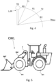
- Fig. 5 shows a work vehicle CWL, for example a so-called “compact wheel loader”.
- This comprises an arm BM and a BKT bucket, wherein the arm has a first end hinged to a vehicular frame F and a second end, opposite to the first, arranged to rotatably support a bucket BKT.
- the lifting of the arm is achieved via the actuator BM shown in Fig. 3 , while a rotation of the bucket with respect to the arm is achieved via the actuator BKT.
- Additional actuators may be present in the vehicle electro-hydraulic circuit HC.
- Each hydraulic actuator corresponds to an open center directional valve V1, V2, V3.
- the open center direction valve hereinafter simply referred to as the "valve" has the task of directing the hydraulic oil to the corresponding actuator or to the collection tank T.
- This operating mode is for convenience called “accelerator_base” mode, in which, that is, the rotation speed ES of the prime mover E is directly proportional to the deflection of the accelerator lever AP and in which the speed VS of the vehicle and the rotation speed of the prime mover are approximately directly proportional to each other. It is important to remember that the accelerator lever and the joystick lever are distinct and separate devices as well as independently operable by the human operator.
- a second operating mode is provided, named as “tool-base” for convenience, in which
- the fixed speed of the first interval R1 is for example 1400 rpm.
- a human/machine interface for example a touchscreen display.
- Fig. 4 shows a diagram of the intervals R0, R1, R2 for operating the joystick lever in a predetermined direction.
- intervals R1 (T1, T2) and R2 (T2, TMax) are continuous and non-degenerate, meaning they are not empty.
- TMax indicates the maximum deflection of the joystick lever, while T0 indicates the release position and therefore R0 (T0, T1).
- the valve has an approximately linear increasing trend in the R1 interval, while in the R2 interval, the valve is constantly open to its maximum value.
- the trend in the R1 and R2 intervals can be for example:
- the selection of said first or second operating mode is achieved by means of a further human/machine interface device different from said accelerator lever and said joystick lever. It can be, for example, a button located on the dashboard or a virtual menu of the touchscreen instrument panel.
- the interval R1 allows the operator to finely control the operated actuator, while the R2 interval allows reducing losses due to hydraulic oil lamination through the V1 - V3 valve.
- the oil flow reaching the hydraulic actuator is controlled exclusively by varying the rotation speed of the prime mover. That is, indirect control of the hydraulic oil flow rate that reaches the actuator is obtained by controlling the rotation speed of the prime mover.
- the range R0 is completely optional and represents the so-called dead band in which a deflection of the joystick lever does not cause anything.
- the deadband R0 is between a position of complete release of the joystick lever and the threshold T1. When indicating the release of the joystick lever, it can implicitly refer to the deadband, which is implemented in any application.
- T1 may be 5 - 10% of the maximum joystick lever deflection
- T2 may be 25% - 35% of the maximum deflection
- the electrical signals generated by the joystick lever and the accelerator lever are sent to the UCM processing unit, which, in relation to the strategies implemented, controls the prime mover and the hydrostat HY, i.e. the displacement of the HP hydraulic pump and/or HM hydraulic motor.
- the deflection of the accelerator lever impacts the rotation speed of the prime mover up to the lower speed limit of the prime mover, once this value is exceeded an action on the accelerator lever determines exclusively a variation of the hydrostat transmission ratio, without any influence on the rotation speed of the prime mover, as happens when the joystick lever is in the second deflection range.
- the vehicle object of the present invention has a series type propulsion system, i.e. in which the prime mover is connected to the wheels WH exclusively through the hydrostat.
- the processing unit is configured to compensate for changes in rotational speed of the prime mover controlled exclusively by the joystick lever, by controlling the displacement of the HP hydraulic pump.
- the speed of the vehicle is immune to variations in the rotation speed of the prime mover, apparently being exclusively a function of the deflection of the accelerator lever.
- the present invention can advantageously be carried out by means of a computer program which includes coding means for carrying out one or more steps of the method, when this program is executed on a computer. It is therefore understood that the scope of protection extends to said computer program and further to computer readable means comprising a recorded message, said computer readable means comprising program coding means for carrying out one or more steps of the method , when said program is run on a computer.
Landscapes
- Engineering & Computer Science (AREA)
- Mining & Mineral Resources (AREA)
- Civil Engineering (AREA)
- General Engineering & Computer Science (AREA)
- Structural Engineering (AREA)
- Physics & Mathematics (AREA)
- Fluid Mechanics (AREA)
- Operation Control Of Excavators (AREA)
- Control Of Vehicle Engines Or Engines For Specific Uses (AREA)
Applications Claiming Priority (1)
| Application Number | Priority Date | Filing Date | Title |
|---|---|---|---|
| IT202300027153 | 2023-12-19 |
Publications (1)
| Publication Number | Publication Date |
|---|---|
| EP4575103A1 true EP4575103A1 (de) | 2025-06-25 |
Family
ID=89983038
Family Applications (1)
| Application Number | Title | Priority Date | Filing Date |
|---|---|---|---|
| EP24220531.8A Pending EP4575103A1 (de) | 2023-12-19 | 2024-12-17 | Verfahren zum betreiben eines hydraulikkreislaufs eines arbeitsfahrzeugs, zugehörige verarbeitungseinheit und arbeitsfahrzeug |
Country Status (1)
| Country | Link |
|---|---|
| EP (1) | EP4575103A1 (de) |
Citations (1)
| Publication number | Priority date | Publication date | Assignee | Title |
|---|---|---|---|---|
| EP3660226A1 (de) * | 2017-09-29 | 2020-06-03 | Hitachi Construction Machinery Co., Ltd. | Radlader |
-
2024
- 2024-12-17 EP EP24220531.8A patent/EP4575103A1/de active Pending
Patent Citations (1)
| Publication number | Priority date | Publication date | Assignee | Title |
|---|---|---|---|---|
| EP3660226A1 (de) * | 2017-09-29 | 2020-06-03 | Hitachi Construction Machinery Co., Ltd. | Radlader |
Similar Documents
| Publication | Publication Date | Title |
|---|---|---|
| US8316983B2 (en) | Construction vehicle | |
| EP1830053B1 (de) | Steuervorrichtung für fahrendes arbeitsfahrzeug | |
| KR101956959B1 (ko) | 단일 입력을 사용해서 리프트 스피드의 전체 범위를 획득하기 위한 방법 | |
| US20090018745A1 (en) | System and method for operating a machine | |
| EP2413005A1 (de) | Erdbewegungsmaschine | |
| WO2002021023A1 (en) | Speed controller of wheel type hydraulic traveling vehicle | |
| EP2940319B1 (de) | Hydraulisches system und verfahren zur steuerung eines hydraulischen systems | |
| US12180683B2 (en) | Work vehicle and control method for work vehicle | |
| JP2008223815A (ja) | メカニカルスロットル車両のオートモーティブ制御装置 | |
| US20140069092A1 (en) | Traction Control System for a Hydrostatic Drive | |
| IT202000016066A1 (it) | Sistema di controllo di una trasmissione idraulica di una macchina da lavoro o agricola | |
| US4015482A (en) | Control system for power train and auxiliary equipment driven from a common prime mover | |
| AU2017426297A1 (en) | Work vehicle and control method for work vehicle | |
| US7210293B2 (en) | Hydrostatic transmission vehicle and hydrostatic transmission controller | |
| JP3936853B2 (ja) | 作業車両の変速装置 | |
| CN108290497B (zh) | 对车辆的压力和速度控制 | |
| EP4575103A1 (de) | Verfahren zum betreiben eines hydraulikkreislaufs eines arbeitsfahrzeugs, zugehörige verarbeitungseinheit und arbeitsfahrzeug | |
| US8290672B2 (en) | Method and a system for controlling a vehicle | |
| US10377223B2 (en) | Working machine arranged with means to drive and control a hydraulic pump | |
| CN113874266B (zh) | 作业车辆以及作业车辆的控制方法 | |
| EP4375104B1 (de) | Verfahren und system zur steuerung eines antriebssystems eines arbeits- oder landwirtschaftlichen fahrzeugs | |
| EP4542089A1 (de) | Verfahren und steuersystem für ein antriebssystem eines arbeits- oder landwirtschaftlichen fahrzeugs | |
| EP4563848A1 (de) | Verfahren und steuerungssystem zur steuerung eines antriebssystems eines arbeits- oder landwirtschaftlichen fahrzeugs | |
| EP4495337A1 (de) | Verfahren und steuersystem zum ansteuern einer rückstellfunktion eines gelenkarms eines arbeits- oder landwirtschaftlichen fahrzeugs | |
| US6067878A (en) | System and method for restricting gear shift operation in timber harvesting tractors |
Legal Events
| Date | Code | Title | Description |
|---|---|---|---|
| PUAI | Public reference made under article 153(3) epc to a published international application that has entered the european phase |
Free format text: ORIGINAL CODE: 0009012 |
|
| STAA | Information on the status of an ep patent application or granted ep patent |
Free format text: STATUS: THE APPLICATION HAS BEEN PUBLISHED |
|
| AK | Designated contracting states |
Kind code of ref document: A1 Designated state(s): AL AT BE BG CH CY CZ DE DK EE ES FI FR GB GR HR HU IE IS IT LI LT LU LV MC ME MK MT NL NO PL PT RO RS SE SI SK SM TR |
|
| STAA | Information on the status of an ep patent application or granted ep patent |
Free format text: STATUS: REQUEST FOR EXAMINATION WAS MADE |
|
| 17P | Request for examination filed |
Effective date: 20260102 |