EP4575110A1 - Soupape de remplissage - Google Patents
Soupape de remplissage Download PDFInfo
- Publication number
- EP4575110A1 EP4575110A1 EP23219900.0A EP23219900A EP4575110A1 EP 4575110 A1 EP4575110 A1 EP 4575110A1 EP 23219900 A EP23219900 A EP 23219900A EP 4575110 A1 EP4575110 A1 EP 4575110A1
- Authority
- EP
- European Patent Office
- Prior art keywords
- valve
- chamber
- volume
- filling valve
- filling
- Prior art date
- Legal status (The legal status is an assumption and is not a legal conclusion. Google has not performed a legal analysis and makes no representation as to the accuracy of the status listed.)
- Withdrawn
Links
Images


Classifications
-
- E—FIXED CONSTRUCTIONS
- E03—WATER SUPPLY; SEWERAGE
- E03D—WATER-CLOSETS OR URINALS WITH FLUSHING DEVICES; FLUSHING VALVES THEREFOR
- E03D1/00—Water flushing devices with cisterns ; Setting up a range of flushing devices or water-closets; Combinations of several flushing devices
- E03D1/30—Valves for high or low level cisterns; Their arrangement ; Flushing mechanisms in the cistern, optionally with provisions for a pre-or a post- flushing and for cutting off the flushing mechanism in case of leakage
- E03D1/32—Arrangement of inlet valves
Definitions
- the present invention relates to a filling valve for a cistern according to the preamble of claim 1.
- the EP 1 175 576 such a filling valve, wherein the water is guided through the filling valve in a water guide channel.
- the filling valve of the EP 1 175 576 has a float-controlled diaphragm valve.
- the filling valve is designed as a diaphragm valve, very high pressure shocks or pressure impulses can even lead to damage to the diaphragm, which ultimately results in a leaky filling valve.
- the present invention is based on the object of providing a filling valve that overcomes the disadvantages of the prior art.
- a particularly preferred object of the present invention is to provide a filling valve that reduces pressure surges during the closing process.
- a filling valve for filling a cistern with flushing water comprises a valve housing, a water guide channel arranged in the valve housing with an inlet and an outlet, wherein flushing water can be guided in the flow direction from the inlet to the outlet, and a controlled, in particular a float-controlled, valve with a valve stem and a valve seat.
- the valve stem can be moved back and forth between a closed position, in which the valve stem rests sealingly on the valve seat with a sealing section such that the water guide channel is closed, and a flow position, in which the valve stem lies with the sealing section spaced from the valve seat such that the water guide channel is open.
- the filling valve further comprises at least one compression unit with a damping element, which damping element provides an output volume, wherein the output volume can be compressed to a compression volume upon the occurrence of a pressure surge resulting from the closing of the valve stem.
- the damping element is designed such that it returns to its original volume after the pressure surge has ceased.
- the damping element is designed to be elastically resilient.
- the at least one damping element has the shape of an elastically formed solid body, which solid body is compressible from the initial volume to the compression volume.
- the at least one damping element has a gas volume, in particular an air volume, which gas volume can be compressed from the initial volume to the compression volume.
- the air volume is filled with air.
- Air has a compression modulus, which is advantageous for pressure surges that occur.
- the at least one compression unit is arranged upstream of the valve seat, as seen in the flow direction of the flushing water.
- the compression unit is preferably arranged between the inlet and the valve seat in the water guide channel.
- the at least one compression unit is an air-filled chamber.
- the chamber is bounded by a wall.
- the wall has an opening which, in the installed position, is located such that a partial volume of the chamber is above the opening, such that if water enters through the opening, the partial volume always contains air.
- the chamber has the shape of a cylinder, in particular a circular cylinder.
- the opening is located on the base surface.
- the cylinder is positioned in the installed position such that its central axis runs horizontally and the opening, when viewed in the installed position, is preferably located on or below the central axis of the cylinder.
- the horizontal runs in a direction perpendicular to the plumb line.
- the wall comprises two spaced-apart base wall sections and a side wall section connecting the two base wall sections.
- one of the two base wall sections is designed as a cover that can be connected to the side wall section, with the other of the two base wall sections being integrally connected to the side wall section.
- said opening is arranged in the cover.
- the cover can preferably be connected to the side wall section in a watertight manner.
- the cover can be connected to the side wall section in a materially bonded manner, in particular via a welded connection.
- the wall has a chamber opening, which is closed with an elastic membrane.
- the chamber is thus delimited or essentially completely delimited by the wall and the elastic membrane.
- the membrane is preferably water-impermeable and attached to the wall in a water-tight manner, thus preventing water from penetrating the chamber.
- the elastic membrane is held in the chamber opening by a bearing ring.
- the filling valve further comprises a control chamber which is separated from the water guide channel by a membrane element.
- the valve stem is mounted in the membrane element.
- the membrane element extends from the valve stem to the wall of the control chamber.
- the membrane element is fixedly mounted in the wall of the control chamber.
- the membrane element has a through-opening which allows the control chamber to be filled with flushing water from the water guide channel.
- the control chamber has a control valve which can be controlled by a control element. When the control valve is open, the membrane element with the valve stem can be moved from the closed position to the flow position due to the water pressure in the water guide channel. When the control valve is closed, the membrane element with the valve stem can be moved from the Flow position movable into the closed position.
- the control element is preferably a float that floats in the cistern and closes the control valve when the specified flush water level is reached.
- the control element can also be designed differently.
- the compression unit is arranged in the control chamber.
- the compression unit or the chamber is arranged on the valve tappet, wherein the compression unit or the chamber is arranged on the valve tappet in such a way that the compression unit or the chamber is located in the control chamber.
- the compression unit can be arranged on the valve tappet.
- the water guide channel is delimited by a side wall, wherein the compression unit is arranged on the side wall or is integrated into the side wall.
- a cylindrical receiving structure is arranged in the water guide channel, wherein the compression unit is annular and rests on the cylindrical receiving structure.
- the filling valve further comprises an insert that is connected to the valve housing in the region of the inlet, wherein the cylindrical receiving structure is provided by the insert.
- the cylindrical receiving structure is part of the valve housing.
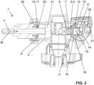
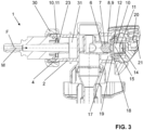
- the figures show a filling valve 1 for filling a cistern with flushing water according to a preferred embodiment of the present invention.
- the flushing water enters the water guide channel 3 via inlet 4 and then flows in a horizontal channel section 31 to the valve 6. From the valve 6, the flushing water flows into a vertical channel section 32.
- the horizontal channel section 31 extends around the vertical channel section 32 shortly before the valve 6.
- the filling valve 1 has at least one compression unit 10 with a damping element 11. As explained further below, two compression units 10 are shown in the illustrated embodiment. However, only one of the two compression units 10 can also be arranged.
- the damping element 11 of the at least one compression unit 10 provides an output volume.
- the output volume can be compressed to a compression volume when a pressure surge occurs when the valve stem 7 closes. This compression can reduce the resulting pressure surge.
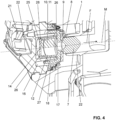
- the first variant of the compression unit 10 is a chamber 12, which is Figures 2 to 4 as well as in the Figures 5a to 5c and in the Figures 6a to 6c is clearly visible.
- the chamber 12 has a volume of air located within the chamber 12 as the damping element 11.
- the chamber 12 is delimited by a wall 13.
- the damping element 11 is a gas volume, in this case an air volume. The gas volume can be compressed from the initial volume to the compression volume.
- the chamber 12 can be arranged in various ways. In the embodiment shown, the chamber 12 is located on the valve stem 7. However, the chamber 12 can also be arranged differently. Here, the chamber 12, as shown by the Figures 4 to 6c visible, the shape of a cylinder, in particular a circular cylinder.
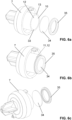
- FIG. 5a to 5c a variant of the compression unit 10 with the chamber 12 is shown.
- Figures 5a and 5b show this variant as exploding views and the Figure 5c shows this variant in the assembled state.
- the wall 13 of the chamber 12 has an opening 14.
- the opening 14 is located in the installed position such that a partial volume 15 of the chamber 15 is above the opening 14, such that when water enters through the opening 14, the partial volume 15 always contains air.
- the partial volume is in the Figure 4 and 5a shown hatched. When the pressure surge occurs, the pressure expands through opening 14 into the chamber and the air volume is compressed.
- the opening 14 is placed here on the base surface 25.
- the cylinder In the installed position, the cylinder is positioned such that its central axis M runs horizontally.
- the opening 14 is preferably located on or below the central axis of the cylinder when viewed in the installed position.
- the wall 13 has two spaced-apart base wall sections 26 and a side wall section 27 connecting the two base wall sections 26.
- One of the two base wall sections 26 is designed as a cover 28.
- the cover 28 is connectable to the side wall section 27.
- the other of the Both base wall sections 26 are integrally connected to the side wall section 27.
- said opening 14 is preferably arranged in the cover 28.
- FIG. 6a to 6c another variant of the compression unit 10 with the chamber 12 is shown.
- Figures 6a and 6b show this variant as exploding views and the Figure 6c shows this variant in the assembled state.
- the wall 13 of the chamber 12 has a chamber opening 33.
- the chamber opening 33 is closed with an elastic membrane 34.
- the elastic membrane 34 extends completely over the cross-section of the chamber opening 33.
- the chamber 12 is, as mentioned above, filled with air. When a pressure surge occurs, the elastic membrane 34 is moved into the chamber 12 and the air volume in the chamber 12 is compressed.
- the elastic membrane 34 is held by a bearing ring 35 in a membrane receptacle 36 in the region of the chamber opening 33.
- the bearing ring 35 can be held in the chamber opening 33 in a force-fitting and/or form-fitting and/or material-fitting manner.
- the elastic membrane 34 preferably closes the chamber 12 completely.
- the at least one compression unit 10 is arranged in front of the valve seat 8, as seen in the flow direction F of the flushing water.
- the filling valve 1 further comprises a control chamber 16, which is separated from the water guide channel by a membrane element 17.
- the valve stem 7 is mounted in the membrane element 17, and the membrane element 17 extends from the valve stem 7 to the wall 18 of the control chamber 16.
- the membrane element 17 has a through-opening 19, which allows the control chamber 16 to be filled with flushing water from the water guide channel 3.
- the control chamber 16 has a control valve 20, which can be controlled by a control element 21.
- the control valve 21 When the control valve 21 is open, the membrane element 17 with the valve stem 7 can be moved from the closed position to the flow position due to the water pressure in the water guide channel 3.
- the control valve 21 is closed, the membrane element 17 with the valve stem 7 can be moved from the flow position to the closed position due to the water pressure in the control chamber 16.
- the control valve 21 is controlled by a float 29, which acts on the control valve via a linkage (not shown).
- the compression unit 10 here the chamber 12, is arranged in the control chamber 16.
- the pressure surge expands through the through-opening 19 in the diaphragm element 17 into the control chamber 16, where it is dampened by the compression unit 10.
- the compression unit 10, preferably the chamber 12, is arranged on the valve tappet 7, as already mentioned above, in the variant shown.
- the compression unit 10 or the chamber 12 is arranged on the valve tappet 7 in such a way that the compression unit 10 or the chamber 12 is located in the control chamber 16.
- the second variant of the compression unit 10 is an elastically formed solid body.
- the solid body can be compressed from the initial volume to the compression volume.
- a particularly preferred embodiment of the solid body is described in the Figures 1 to 3 shown.
- a cylindrical receiving structure 23 is arranged in the water guide channel 3, wherein the compression unit is annular and rests on the cylindrical receiving structure.
- the filling valve further comprises an insert 24.
- the insert 24 is connected to the valve housing 2 in the region of the inlet 4.
- the cylindrical receiving structure 23 is provided by the insert 24.
- the insert 24 is secured to the valve housing 2 via a union nut 30.
- the cylindrical receiving structure 23 can also be arranged on the valve housing.
- the compression volume is preferably in the range of 30% to 95%, in particular in the range of 50% to 90%, of the initial volume.
- the initial volume is in the range of 150 mm 3 to 2000 mm 3 , in particular in the range of 250 mm 3 to 1500 mm 3 .
Landscapes
- Health & Medical Sciences (AREA)
- Life Sciences & Earth Sciences (AREA)
- Engineering & Computer Science (AREA)
- Hydrology & Water Resources (AREA)
- Public Health (AREA)
- Water Supply & Treatment (AREA)
- Lift Valve (AREA)
Priority Applications (1)
| Application Number | Priority Date | Filing Date | Title |
|---|---|---|---|
| EP23219900.0A EP4575110A1 (fr) | 2023-12-22 | 2023-12-22 | Soupape de remplissage |
Applications Claiming Priority (1)
| Application Number | Priority Date | Filing Date | Title |
|---|---|---|---|
| EP23219900.0A EP4575110A1 (fr) | 2023-12-22 | 2023-12-22 | Soupape de remplissage |
Publications (1)
| Publication Number | Publication Date |
|---|---|
| EP4575110A1 true EP4575110A1 (fr) | 2025-06-25 |
Family
ID=89321509
Family Applications (1)
| Application Number | Title | Priority Date | Filing Date |
|---|---|---|---|
| EP23219900.0A Withdrawn EP4575110A1 (fr) | 2023-12-22 | 2023-12-22 | Soupape de remplissage |
Country Status (1)
| Country | Link |
|---|---|
| EP (1) | EP4575110A1 (fr) |
Citations (4)
| Publication number | Priority date | Publication date | Assignee | Title |
|---|---|---|---|---|
| US1621910A (en) * | 1925-05-23 | 1927-03-22 | Thomson | Valve |
| US3401716A (en) * | 1964-03-11 | 1968-09-17 | West H. Gallogly | Toilet flush valve |
| EP1175576A1 (fr) | 1999-05-11 | 2002-01-30 | Geberit Technik Ag | Garniture d'arrivee d'eau pour un reservoir de chasse |
| EP4095325A1 (fr) * | 2021-05-28 | 2022-11-30 | Geberit International AG | Soupape de remplissage |
-
2023
- 2023-12-22 EP EP23219900.0A patent/EP4575110A1/fr not_active Withdrawn
Patent Citations (4)
| Publication number | Priority date | Publication date | Assignee | Title |
|---|---|---|---|---|
| US1621910A (en) * | 1925-05-23 | 1927-03-22 | Thomson | Valve |
| US3401716A (en) * | 1964-03-11 | 1968-09-17 | West H. Gallogly | Toilet flush valve |
| EP1175576A1 (fr) | 1999-05-11 | 2002-01-30 | Geberit Technik Ag | Garniture d'arrivee d'eau pour un reservoir de chasse |
| EP4095325A1 (fr) * | 2021-05-28 | 2022-11-30 | Geberit International AG | Soupape de remplissage |
Similar Documents
| Publication | Publication Date | Title |
|---|---|---|
| EP3551808B1 (fr) | Vanne d'eau sous pression | |
| DE69412571T2 (de) | Servodruckregler | |
| EP1004715A1 (fr) | Dispositif anti-retour | |
| EP1654464B1 (fr) | Dispositif d'amortissement de coups de belier | |
| EP1570137A1 (fr) | Piece sanitaire encastree | |
| EP4127490B1 (fr) | Soupape de freinage doté d'un dispositif d'étanchéité et procédé associé | |
| DE102012102701B3 (de) | Rohrtrenneranordnung | |
| EP0999392B1 (fr) | Servo-soupape actionnée par son propre fluide, en particulier une soupape magnétique pour des armatures sanitaires | |
| DE3626337C2 (de) | Druckstoßdämpfer für Wasserleitungen | |
| DE102006052248B3 (de) | Druckmindereranordnung | |
| EP4116511B1 (fr) | Soupape de remplissage | |
| DE102005056068B4 (de) | Überdruck-Schließventil | |
| CH639733A5 (en) | Hydraulic damping device, especially for damping the movement of the closure piece of a valve | |
| DE602004009491T2 (de) | Ausdehnungsgefäß mit Ventil | |
| DE69219098T2 (de) | Kartusche für keramische Mischventilscheiben | |
| DE3834997C2 (fr) | ||
| EP4116512B1 (fr) | Soupape de remplissage | |
| DE19834902B4 (de) | Kugel-Rückschlagventil | |
| DE69200205T2 (de) | Sicherheitsventil für den Entlüftungskreislauf eines Kfz-Kraftstoffbehälters. | |
| DE102009048093B4 (de) | System- oder Rohrtrenner in Modulbauweise als Patrone | |
| DE3317877A1 (de) | Druckspueler fuer wasserklosetts | |
| DE10048689B4 (de) | Heizkörperventil | |
| DE2710527A1 (de) | Ventil zum absperren von druckmedien | |
| EP1650361B1 (fr) | Elément sanitaire | |
| DE2759900C2 (de) | Rückschlagventil mit Dämpfungseinrichtung |
Legal Events
| Date | Code | Title | Description |
|---|---|---|---|
| PUAI | Public reference made under article 153(3) epc to a published international application that has entered the european phase |
Free format text: ORIGINAL CODE: 0009012 |
|
| STAA | Information on the status of an ep patent application or granted ep patent |
Free format text: STATUS: THE APPLICATION HAS BEEN PUBLISHED |
|
| AK | Designated contracting states |
Kind code of ref document: A1 Designated state(s): AL AT BE BG CH CY CZ DE DK EE ES FI FR GB GR HR HU IE IS IT LI LT LU LV MC ME MK MT NL NO PL PT RO RS SE SI SK SM TR |
|
| STAA | Information on the status of an ep patent application or granted ep patent |
Free format text: STATUS: THE APPLICATION IS DEEMED TO BE WITHDRAWN |
|
| 18D | Application deemed to be withdrawn |
Effective date: 20260103 |