EP4575120A1 - Élément de construction - Google Patents
Élément de construction Download PDFInfo
- Publication number
- EP4575120A1 EP4575120A1 EP24216523.1A EP24216523A EP4575120A1 EP 4575120 A1 EP4575120 A1 EP 4575120A1 EP 24216523 A EP24216523 A EP 24216523A EP 4575120 A1 EP4575120 A1 EP 4575120A1
- Authority
- EP
- European Patent Office
- Prior art keywords
- supporting beam
- construction element
- recess
- insulation material
- core
- Prior art date
- Legal status (The legal status is an assumption and is not a legal conclusion. Google has not performed a legal analysis and makes no representation as to the accuracy of the status listed.)
- Granted
Links
Images


Classifications
-
- E—FIXED CONSTRUCTIONS
- E04—BUILDING
- E04B—GENERAL BUILDING CONSTRUCTIONS; WALLS, e.g. PARTITIONS; ROOFS; FLOORS; CEILINGS; INSULATION OR OTHER PROTECTION OF BUILDINGS
- E04B7/00—Roofs; Roof construction with regard to insulation
- E04B7/20—Roofs consisting of self-supporting slabs, e.g. able to be loaded
- E04B7/22—Roofs consisting of self-supporting slabs, e.g. able to be loaded the slabs having insulating properties, e.g. laminated with layers of insulating material
-
- E—FIXED CONSTRUCTIONS
- E04—BUILDING
- E04B—GENERAL BUILDING CONSTRUCTIONS; WALLS, e.g. PARTITIONS; ROOFS; FLOORS; CEILINGS; INSULATION OR OTHER PROTECTION OF BUILDINGS
- E04B1/00—Constructions in general; Structures which are not restricted either to walls, e.g. partitions, or floors or ceilings or roofs
- E04B1/62—Insulation or other protection; Elements or use of specified material therefor
- E04B1/74—Heat, sound or noise insulation, absorption, or reflection; Other building methods affording favourable thermal or acoustical conditions, e.g. accumulating of heat within walls
- E04B1/88—Insulating elements for both heat and sound
- E04B1/90—Insulating elements for both heat and sound slab-shaped
-
- E—FIXED CONSTRUCTIONS
- E04—BUILDING
- E04C—STRUCTURAL ELEMENTS; BUILDING MATERIALS
- E04C2/00—Building elements of relatively thin form for the construction of parts of buildings, e.g. sheet materials, slabs, or panels
- E04C2/02—Building elements of relatively thin form for the construction of parts of buildings, e.g. sheet materials, slabs, or panels characterised by specified materials
- E04C2/26—Building elements of relatively thin form for the construction of parts of buildings, e.g. sheet materials, slabs, or panels characterised by specified materials composed of materials covered by two or more of groups E04C2/04, E04C2/08, E04C2/10 or of materials covered by one of these groups with a material not specified in one of the groups
- E04C2/284—Building elements of relatively thin form for the construction of parts of buildings, e.g. sheet materials, slabs, or panels characterised by specified materials composed of materials covered by two or more of groups E04C2/04, E04C2/08, E04C2/10 or of materials covered by one of these groups with a material not specified in one of the groups at least one of the materials being insulating
- E04C2/292—Building elements of relatively thin form for the construction of parts of buildings, e.g. sheet materials, slabs, or panels characterised by specified materials composed of materials covered by two or more of groups E04C2/04, E04C2/08, E04C2/10 or of materials covered by one of these groups with a material not specified in one of the groups at least one of the materials being insulating composed of insulating material and sheet metal
-
- E—FIXED CONSTRUCTIONS
- E04—BUILDING
- E04C—STRUCTURAL ELEMENTS; BUILDING MATERIALS
- E04C2/00—Building elements of relatively thin form for the construction of parts of buildings, e.g. sheet materials, slabs, or panels
- E04C2/02—Building elements of relatively thin form for the construction of parts of buildings, e.g. sheet materials, slabs, or panels characterised by specified materials
- E04C2/26—Building elements of relatively thin form for the construction of parts of buildings, e.g. sheet materials, slabs, or panels characterised by specified materials composed of materials covered by two or more of groups E04C2/04, E04C2/08, E04C2/10 or of materials covered by one of these groups with a material not specified in one of the groups
- E04C2/284—Building elements of relatively thin form for the construction of parts of buildings, e.g. sheet materials, slabs, or panels characterised by specified materials composed of materials covered by two or more of groups E04C2/04, E04C2/08, E04C2/10 or of materials covered by one of these groups with a material not specified in one of the groups at least one of the materials being insulating
- E04C2/296—Building elements of relatively thin form for the construction of parts of buildings, e.g. sheet materials, slabs, or panels characterised by specified materials composed of materials covered by two or more of groups E04C2/04, E04C2/08, E04C2/10 or of materials covered by one of these groups with a material not specified in one of the groups at least one of the materials being insulating composed of insulating material and non-metallic or unspecified sheet-material
-
- E—FIXED CONSTRUCTIONS
- E04—BUILDING
- E04D—ROOF COVERINGS; SKY-LIGHTS; GUTTERS; ROOF-WORKING TOOLS
- E04D3/00—Roof covering by making use of flat or curved slabs or stiff sheets
- E04D3/35—Roofing slabs or stiff sheets comprising two or more layers, e.g. for insulation
- E04D3/351—Roofing slabs or stiff sheets comprising two or more layers, e.g. for insulation at least one of the layers being composed of insulating material, e.g. fibre or foam material
- E04D3/352—Roofing slabs or stiff sheets comprising two or more layers, e.g. for insulation at least one of the layers being composed of insulating material, e.g. fibre or foam material at least one insulating layer being located between non-insulating layers, e.g. double skin slabs or sheets
Definitions
- the invention relates to a construction element, as well as to methods of producing the construction element and hoisting the construction element.
- the construction element according to the invention comprises at least a core of insulation material and a first supporting beam.
- This kind of construction element is known in the prior art, for example from EP 0 775 787 , where the four edges of the construction element are reinforced by means of a supporting beam on each edge in such a way that the construction element is self-supporting, with the supporting beams having the same height as the core of insulation material.
- this has the drawback that such a construction element has thermal bridges.
- EP 2 141 299 describes a construction element with at least a core of insulation material, a first supporting beam, and plate material on both sides of the core of insulation material, in which thermal bridges are prevented by the supporting beams in the core of insulation material not being as high as the thickness of the core of insulation material next to the supporting beam(s).
- elements are attached to the supporting beam to which hoisting means may be attached, wherein these elements pass through the plate material and protrude beyond the outer face of the plate material.
- there is no description of the way in which such elements may be attached nor whether the elements pass through the plate material on the top side of the core of insulation material or on the bottom side of the core of insulation material.
- the fact that the elements to which hoisting means can be attached protrude beyond the outer face of the plate material also has the drawback that it makes the finishing of the construction element after installation more difficult, leading to a risk of the finished construction element not being watertight.
- EP 2 273 024 describes a construction element with at least a core of insulation material, a first supporting beam, a top panel, and a baseplate, wherein the top panel and the baseplate are acoustically uncoupled from each other, in other words wherein the top panel and baseplate are connected to each other by the core of insulation material and not by the first supporting beam.
- an air chamber is provided at the location of the supporting beam between the baseplate and the top panel, wherein the air chamber extends along the entire length of the supporting beam.
- the aim of the construction element according to the present invention is that it can be hoisted in a safer and stabler manner with respect to prior-art construction elements.
- the construction element according to the present invention comprises at least a core of insulation material, situated between a top surface and a bottom surface of the construction element, and at least a first supporting beam between a top surface and a bottom surface of the construction element, wherein the first supporting beam extends along a longitudinal direction of the construction element, wherein the thickness of the core of insulation material is greater than the height of the first supporting beam along at least a part of the - and preferably along the entire - length of the construction element, wherein insulation material of the core of insulation material is situated above the first supporting beam along at least a part of the - and preferably along the entire - length of the first supporting beam, characterized in that the construction element is provided with a first recess through at least a part of the thickness of the core of insulation material, wherein the first recess is situated above - or at least partly above - the first supporting beam, wherein the first recess preferably extends up to the top surface of the construction element.
- the first recess is a local recess, for example having a cylindrical shape, which does not extend along the entire length of the first supporting beam.
- This has the advantage that the thermal resistance of the construction element is only reduced locally.
- a recess with a cylindrical shape has the advantage that it can easily be produced by means of a milling operation.
- other shapes for example a conical or beam-like shape, are also conceivable.
- the first recess is configured in such a way that insulation material of the core of insulation material is situated between the first recess and the first supporting beam. This has the advantage that the thermal resistance of the construction element is reduced very little by the presence of the first recess.
- the depth of the first recess is not more than 10 cm, more preferably not more than 5 cm, and most preferably not more than 2 cm, with there preferably being insulation material of the core of insulation material present between the first supporting beam and the first recess. This has the advantage that the thermal resistance of the construction element is reduced very little by the presence of the first recess.
- the width of the slot decreases as its depth in the core of insulation material increases. This is advantageous in order to simplify the fitting of the first supporting beam in the slot in the core of insulation material. It is also conceivable for the width of the first supporting beam not to be constant across its height, with the width preferably being greater on the bottom side than on the top side of the first supporting beam. This has the advantage that the first supporting beam is wedged in the core of insulation material, which results in a better transmission of the forces. Obviously, a synergetic combination of both is also possible.
- the first supporting beam preferably has a rectangular cross section, although other cross sections, such as the cross section of an I-profile, a C-profile, a tubular profile, or another kind of profile, are also conceivable.
- the cross section has a greater surface moment of inertia about the horizontal axis than about the vertical axis. This has the advantage that a greater resistance to bending is achieved, which is good for the self-supporting character of the construction element.
- the first supporting beam is preferably at least partly made of wood or metal, although the use of a different material is not excluded, preferably a different material whose stiffness is sufficiently high to have a self-supporting construction element.
- the first supporting beam it is not necessary for the first supporting beam to be made in a single piece. It is also possible for several smaller parts to be connected to each other and thus to form a supporting beam. In this case, it is important for the smaller parts to be connected to each other in such a way that the supporting beam functions as one constructional unit. This has the advantage that smaller parts can be re-used. A further advantage thereof is that, if desired, the surface moment of inertia of the supporting beam can be adjusted to the expected local loads.
- the first supporting beam is adhesively bonded to the core of insulation material on at least one side - and preferably on both sides - preferably using a polyurethane glue.
- the top surface of the first supporting beam may be adhesively bonded to the core of insulation material, preferably using a polyurethane glue.
- a baseplate is attached to the bottom side of the core of insulation material.
- the baseplate is preferably attached to the core of insulation material by means of an adhesive connection - preferably using a hotmelt glue, more preferably using a hotmelt polyurethane glue, although other methods are obviously not excluded either.
- the first supporting beam is mechanically connected to the baseplate by means of at least one screw, more preferably by means of at least two screws. This has the advantage that there is a strong connection between the baseplate and the first supporting beam.
- the use of an adhesive connection, a nail connection, a connection using staples or another connection method or a combination thereof is not excluded.
- there is contact between the first supporting beam and the baseplate is more rigid.
- the first supporting beam is connected to the baseplate by means of an adhesive connection, more preferably by a foaming polyurethane glue.
- an adhesive connection more preferably by a foaming polyurethane glue.
- the first supporting beam is connected to the baseplate by means of an adhesive connection
- the first supporting beam is preferably not connected by means of mechanical attachment means, such as screws, staples or nails.
- the aforementioned baseplate may be selected from the following list: particleboards, HDF (high density fibreboard) panels, MDF (medium density fibreboard) panels, OSB (oriented strand board) panels, CLT (construction laminated timber) panels, multiplex panels, or another kind of panels.
- the baseplate has a thickness of at least 8 mm, preferably at least 10 mm, more preferably at least 12 mm, and most preferably at least 14 mm. Obviously, it is also possible for the baseplate to be thinner than 8 mm.
- a top panel is attached to the top side of the core of insulation material, with the first recess passing completely through the thickness of the top panel and through at least a part of the thickness of the core of insulation material.
- insulation material of the core of insulation material present between the first recess and the first supporting beam. This has the advantage that the thermal resistance of the construction element is preserved as much as possible.
- the core of insulation material is preferably attached to the top panel by means of an adhesive connection, although other methods are obviously not excluded.
- the top panel may be selected from the following list: particleboards, HDF (high density fibreboard) panels, MDF (medium density fibreboard) panels, OSB (oriented strand board) panels, CLT (construction laminated timber) panels, multiplex panels, or another kind of panels.
- the top panel has a thickness of at least 8 mm, preferably at least 10 mm, more preferably at least 12 mm, and most preferably at least 14 mm. Obviously, it is also possible for the top panel to be thinner than 8 mm. There is no requirement for the top panel and baseplate to choose the same thickness and/or type of panel, although it would be advantageous from a technical stock-keeping perspective. It is advisable to choose the top panel to be thicker than the baseplate.
- the core of insulation material is composed of one single layer, due to the simplicity of producing such a core of insulation material.
- the core of insulation material may be composed of at least two layers of insulation material which are adhesively bonded to each other, in which case it is not necessary for the at least two layers to be the same kind of insulation material, nor for the at least two layers to have the same thickness.
- the core of insulation material may be constructed on the basis of the intended characteristics, such as a high thermal resistance and/or acoustic damping.
- the layer - or each of the layers - of insulation material comprising the core of insulation material comprises at least one of following materials: expanded polystyrene (EPS), extruded polystyrene (XPS), polyurethane (PUR), polyisocyanurate (PIR), mineral wool, or another insulation material.
- EPS expanded polystyrene
- XPS extruded polystyrene
- PUR polyurethane
- PIR polyisocyanurate
- mineral wool or another insulation material.
- the total thickness of the core of insulation material is between 130 mm and 240 mm, which makes it possible to attain a thermal resistance, calculated according to standard ISO6946:2017, of 8 (m 2 K)/W or even of 10 (m 2 K)/W.
- the first recess comprises an element to which a hoisting means may be attached, wherein the element to which a hoisting means may be attached is anchored to the first supporting beam - preferably by this element being screwed in.
- the aforementioned element may be a lifting eye, pivotable or non-pivotable, a ring bolt, an eye nut, an eye screw, a lifting sling, a screw, or a hook.
- the first recess is sufficiently deep, so that the aforementioned element is at least partly in the recess, with the element not protruding beyond the top surface of the construction element.
- the construction element can easily be given a watertight finish after installation of the construction element.
- the aforementioned element is a pivotable lifting eye, with the pivotable lifting eye being directed upwards and preferably protruding above the top surface of the construction element during hoisting of the construction element, and wherein the pivotable lifting eye is in an, at least partly, folded-in position and may be situated completely under the top surface of the construction element when the construction element is not being hoisted.
- the width of the first recess, in which an element to attach a hoisting means to is present is narrower than the width of the first supporting beam.
- the width of the first recess is between 2 cm and 4 cm, for example 2.5 cm. This has the advantage that the thermal resistance of the construction element changes very little, and the construction element can be hoisted in a simple manner.
- the width of the first recess, in which an element to attach a hoisting means to is present is wider than the width of the first supporting beam. This has the advantage that the aforementioned element is readily accessible and a hoisting means can easily be attached to the aforementioned element.
- the top side of the element to which a hoisting means may be attached does not protrude above the top surface of the insulation material. This has the advantage that the recess in which the element is situated can very easily be given a watertight finish. According to another preferred embodiment, in which a top panel is present, the top side of the element to which a hoisting means may be attached comes as far as between the bottom surface of the top panel and the top surface of the top panel. This has the advantage that the aforementioned element is readily accessible, which offers the further advantage that the aforementioned hoisting means can easily be fitted.
- At least one side surface and/or the top surface of the first supporting beam is connected to the core of insulation material by means of an adhesive connection, more preferably by means of a polyurethane glue.
- counterbattens are arranged on the top side of the top panel.
- the counterbattens may be attached by means of glue, staples, nails, screws, another connecting means, or a combination of the aforementioned options.
- glue is first used to firstly position the counterbattens, after which these are connected mechanically to the top panel by means of staples. This has the advantage that the counterbattens may be positioned accurately.
- the construction element comprises a first additional recess above, or at least partly above, the first supporting beam, wherein the first additional recess above the first supporting beam is configured such that there is insulation material of the core of insulation material between the first additional recess and the first supporting beam.
- the first additional recess is provided with an element to which a hoisting means may be attached, wherein the element is anchored to the first supporting beam situated underneath and does not protrude above the top surface of the construction element.
- the construction element comprises a second supporting beam, wherein insulation material of the core of insulation material is present along at least a part of the - and preferably along the entire - length of the second supporting beam next to the second supporting beam, wherein the construction element is provided with a second recess through at least a part of the thickness of the core of insulation material, wherein the second recess is situated above, or at least partly above, the second supporting beam, wherein the second recess is configured in such a way that insulation material of the core of insulation material is present between the second recess and the second supporting beam.
- the presence of the second supporting beam has the advantage that the stiffness of the construction element is greater. This also has the further advantage that the construction element can be hoisted in a safer manner.
- the second recess is provided with an element to which a hoisting means may be attached, wherein the element is anchored to the second supporting beam situated underneath and does not protrude above the top surface of the construction element.
- a longitudinal side surface of the first supporting beam and/or of the second supporting beam is situated in a longitudinal side surface of the construction element.
- a longitudinal side surface of the first supporting beam, but not of the second supporting beam may be situated in a longitudinal side surface of the construction element. This may have certain advantages for the connection of several construction elements according to the invention.
- both the first supporting beam and the second supporting beam may bear against insulation material of the core of insulation material on both sides.
- This embodiment has the advantage that it achieves better connection between construction elements, since these supporting beams are not always straight or do not always remain straight; whereas longitudinal side surfaces of the construction element produced in the core of insulation material can be given a pleasingly straight and flat finish and also remain flat and straight.
- the construction element is provided with a third recess through at least a part of the thickness of the core of insulation material, wherein the third recess is situated above, or at least partly above, the first supporting beam or the second supporting beam or an optional third supporting beam; wherein, if an optional third supporting beam is present, the thickness of the core of insulation material is greater than the height of the optional third supporting beam along at least a part of the length of the construction element, wherein, if an optional third supporting beam is present, insulation material of the core of insulation material is situated above the optional third supporting beam along at least a part of the - and preferably along the entire - length of the optional third supporting beam, wherein, if an optional third supporting beam is present, insulation material of the core of insulation material is situated next to the optional third supporting beam along at least a part of the - and preferably along the entire - length of the optional third supporting beam.
- the optional presence of a third supporting beam has the advantage that the stiffness of the construction element is increased further, which has the further advantage that
- the construction element is provided with a first recess, a second recess and a third recess, wherein each recess is provided with an element to which a hoisting means may be attached, wherein the element is anchored in the supporting beam situated underneath and wherein the element preferably does not protrude above the top surface of the construction element. It is advisable for the three aforementioned elements not to be collinear, in other words for the three of them not to be aligned.
- the distance between the centre of gravity of the largest possible convex polygon, formed by the at least three non-collinear elements to which a hoisting means may be attached, and the centre of gravity of the plane defined by the edges of the construction element is less than 50%, more preferably less than 30%, still more preferably less than 10%, of the width of the construction element.
- the construction element comprises a first supporting beam, a second supporting beam, a first recess above the first supporting beam, a first additional recess above the first supporting beam, a second recess above the second supporting beam, and a second additional recess above the second supporting beam, wherein the first additional recess is situated above, or at least partly above, the first supporting beam, wherein the first additional recess above the first supporting beam is configured so that insulation material of the core of insulation material is present between the first additional recess above the first supporting beam and the first supporting beam, wherein insulation material of the core of insulation material is situated next to the second supporting beam along at least a part of the - and preferably along the entire - length of the second supporting beam, wherein the construction element is provided with a second recess through at least a part of the thickness of the core of insulation material, wherein the second recess is situated above, or at least partly above, the second supporting beam; wherein the second recess is configured such that insulation material of the core of insulation
- the first recess, the first additional recess, the second recess, and the second additional recess define a quadrangle, and preferably a rectangle.
- the first recess, the first additional recess, the second recess, and the second additional recess each comprise an element to which a hoisting means may be attached, preferably wherein these elements do not protrude above the top surface of the construction element.
- first supporting beam and the second supporting beam are each situated in a different half of the width of the construction element, which increases the general stiffness of the construction element and the stability during hoisting. It is furthermore preferred if both the first supporting beam and the second supporting beam, in their own half of the construction element, are situated closer to the side of the construction element than to the centre of the width of the construction element. This results in a large surface of the quadrangle defined by the four aforementioned elements, which has the advantage that the construction element can be hoisted in a very stable manner.
- At least one of the longitudinal side surfaces - preferably both longitudinal side surfaces - of the construction element are provided with a slot.
- This slot offers the possibility to connect two construction elements according to the invention to each other by means of a connecting means, such as for example an elastic spring.
- a connecting means such as for example an elastic spring.
- the construction element with a male connecting means on one side of the construction element and a female connecting means on the other side of the construction element, wherein the male connecting means and the female connecting means mate. This has the advantage that two construction elements according to the invention can easily be connected to each other without requiring additional material.
- At least the first recess is sealed watertight, preferably by means of a self-adhesive patch, a roof screen, a cover, or another cover means. It is possible that - preferably in addition to the watertight sealing of at least the first recess - at least the first recess is filled with insulation material. This has the advantage that the thermal resistance and the strength, mainly compressive strength, of the construction element are increased locally. However, it is not obligatory to fill the first recess.
- the length of the construction element according to the invention may be up to 8 metres, but the construction element may also be longer.
- the width of the construction element is preferably 60 cm, 80 cm or 120 cm, since these are the standard widths of construction elements which are currently available on the market. Obviously, the width may be adjusted if this is desirable for a specific use.
- the total thickness of the construction element is preferably between 10 cm and 40 cm, and more preferably between 15 cm and 25 cm, wherein the thickness has to be selected on the basis of the desired value for the thermal resistance. For larger dimensions of the construction element - mainly along the length and/or the width - it may be desirable for one or more additional supporting beams to be present so that the stiffness of the construction element is sufficiently large for it to be self-supporting.
- the first recess extends up to the top surface of the construction element; wherein the first recess extends parallel to the first supporting beam; and wherein the first recess extends up to an edge of the core of insulation material.
- the first recess extends as far as on the first supporting beam.
- a beam may be attached in the first recess, on the first supporting beam, for example by means of screws or by means of another attachment method.
- This beam may be used to attach an overhang to the construction element.
- a gutter overhang if the construction element is a roof element.
- the first supporting beam may, at least on a part of the first recess - and preferably along the entire length of the first recess - in the direction perpendicular to the construction element be less high than outside of it. This makes it possible to attach a beam of adequate dimensions in the first recess on the first supporting beam.
- the first recess may be provided in the construction element beforehand.
- the beam may be attached on site after the construction element has been positioned. This makes transportation and installation of the construction element easier.
- a beam may be attached to the first supporting beam; with this beam preferably making contact with the first supporting beam. More preferably, this beam protrudes beyond an edge of the core of insulation material.
- This beam may be used to attach an overhang to the construction element, for example to attach a gutter overhang if the construction element is a roof element.
- the beam does not protrude above the top surface of the construction element; more preferably the top side of the beam is situated in the top surface of the construction element. This ensures that a covering can easily be arranged on the construction element.
- the construction element is a roof element, the beam does not impede the fitting of counterbattens, tiling battens and roof tiles.
- a second recess may also be provided above a second supporting beam in a way similar to the recess in the first recess, and to have the same characteristics.
- a second beam may be arranged in the second recess on the second supporting beam in a way similar to the beam in the first recess on the first supporting beam. This may be used to attach an overhang on the beam and on the second beam.
- a preferred embodiment of the construction element is characterized in that the construction element comprises a second supporting beam- preferably parallel to the first supporting beam -, in which the construction element comprises a recess in the core of insulation material and perpendicular to the longitudinal direction of the first supporting beam, wherein the recess runs along the first supporting beam and the second supporting beam, wherein the recess extends up to an edge of the core of insulation material.
- the recess extends as far as on the first supporting beam and as far as on the second supporting beam.
- This recess may be used to attach a lateral beam therein, on the first supporting beam and on the second supporting beam.
- This lateral beam may protrude on an edge of the core of insulation material, and may be used to attach an end face overhang to if the construction element is a roof element.
- the first supporting beam and the second supporting beam are less high at the recess than outside thereof. This makes it possible to attach a lateral beam of adequate dimensions in the first recess on the first supporting beam.
- a lateral beam is attached to the first supporting beam and to the second supporting beam in the recess. More preferably, this lateral beam makes contact with the first supporting beam and with the second supporting beam.
- the lateral beam preferably extends beyond an edge of the core of insulation material.
- the lateral beam does not protrude above the top surface of the construction element. More preferably, the top side of the lateral beam is situated in the top surface of the construction element. This ensures that a covering can easily be arranged on the construction element. For example, if the construction element is a roof element, the beam does not impede the fitting of counterbattens, tiling battens and roof tiles.
- the construction element according to the invention is mainly intended as a roof element, even if it can also be used as a wall element, as a floor element or as a ceiling element.
- the present invention also comprises the combination of all preceding embodiments and their specific characteristics, in so far as these do not contradict one another. It is assumed that the person skilled in the art has sufficient knowledge to be able to make a suitable choice in case of contradictory possibilities.
- the invention furthermore also comprises a method for manufacturing a construction element according to the invention, comprising at least the following steps:
- the invention furthermore also comprises a method for manufacturing a construction element according to the invention, comprising at least the following steps:
- the invention furthermore also comprises a method for installing a construction element according to the invention, comprising at least the following steps:
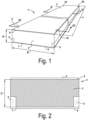
- Fig. 1 shows a perspective view of a preferred embodiment of a construction element 1 according to the invention.
- the construction element 1 has a length L, a width B and a height H.
- the construction element 1 has a core of insulation material 2 which is situated between a top surface 3 and a bottom surface 4.
- the construction element 1 in the embodiment in Fig. 1 furthermore also has a first supporting beam 5, situated between the top surface 3 and the bottom surface 4, which extends in the longitudinal direction of the construction element 1, which bears against the core of insulation material 2 along one of the sides, and a second supporting beam 6, situated between the top surface 3 and the bottom surface 4, which bears against the core of insulation material 2 along one of the sides.
- insulation material of the core of insulation material 2 present above both the first supporting beam 5 and above the second supporting beam 6, along the entire length of both the first supporting beam 5 and the second supporting beam 6.
- Above the second supporting beam 6, there are two local recesses 15, 20 which run through the entire thickness of the top panel 8 and through a part of the thickness of the insulation material of the core of insulation material 2.
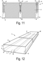
- Fig. 2 shows, in front view, a cross section along line II-II in Fig. 1 of an embodiment of a construction element 1, wherein the core of insulation material 2 at the top adjoins the top panel 8, at the bottom adjoins the baseplate 7, wherein both the first supporting beam 5 and the second supporting beam 6, both situated between the top panel 8 and the baseplate 7, with one side surface adjoin the core of insulation material 2, and wherein insulation material of the core of insulation material 2 is present between the top side of the first supporting beam 5 and the top panel 8, and also between the top side of the second supporting beam 6 and the top panel 8.
- This cross section of the construction element 1 is characterized by the top surface of the core of insulation material 2 continuing uninterrupted across the complete cross section and having a nominal thickness D in locations where there is no supporting beam.
- a majority - and more preferably the vast majority - of the possible cross sections of the construction element 1 has this characteristic feature since it is good for the thermal resistance of the construction element 1.
- Fig. 3 shows, in front view, a cross section along line III-III in Fig. 1 of a preferred embodiment of a construction element 1, wherein the core of insulation material 2 at the top adjoins the top panel 8, at the bottom adjoins the baseplate 7, wherein both the first supporting beam 5 and the second supporting beam 6, both situated between the top panel 8 and the baseplate 7, with one side surface adjoin the core of insulation material 2, and wherein insulation material of the core of insulation material 2 is present above the first supporting beam 5 and also above the second supporting beam 6.
- This cross section of the construction element 1 is characterized by the fact that there is a first recess 9 above the first supporting beam 5, wherein insulation material of the core of insulation material 2 is present between the first supporting beam 5 and the first recess 9, and wherein the first recess 9 is open along the top, and wherein there is a second recess 15 above the second supporting beam 6, wherein insulation material of the core of insulation material 2 is present between the second supporting beam 6 and the second recess 15, and wherein the second recess 15 is open along the top.
- the first recess 9 and the second recess 15 are local recesses which do not extend along the entire length of the construction element 1, which has the advantage that the thermal resistance of the construction element 1 is virtually equal to the thermal resistance of a construction element 1 without recesses 9, 15.
- Fig. 4 shows, in front view, a cross section along line III-III in Fig. 1 of an alternative embodiment of a construction element 1.
- the construction element 1 comprises a top surface 3 and a bottom surface 4 between which there is a core of insulation material 2, a first supporting beam 5 situated between the top surface 3 and the bottom surface 4, a first recess 9 above - or at least partly above - the first supporting beam 5, wherein insulation material of the core of insulation material 2 is present between the first supporting beam 5 and the first recess 9, and wherein the first recess 9 is open along the top.
- the first recess 9 is a local recess which does not extend along the entire length of the construction element 1, which has the advantage that the thermal resistance of the construction element 1 is virtually equal to the thermal resistance of a construction element 1 without recess 9.
- at least one side surface and/or the top surface of the first supporting beam 5 is adhesively bonded to the core of insulation material 2.
- Fig. 5 shows, in front view, a cross section along line III-III in Fig. 1 of an alternative embodiment of a construction element 1 with the characteristic feature that there is a baseplate 7 on the bottom side of the core of insulation material 2 and a top panel 8 on the top side of the core of insulation material 2. Both the baseplate 7 and the top panel 8 are optional.
- the baseplate 7 and the first supporting beam 5 are mechanically connected to each other by means of screws, nails, staples, or another connecting method.
- there is contact between the baseplate 7 and the first supporting beam 5 which results in an advantageous stiffer connection, even if, according to the invention, it is also conceivable for there to be no contact.
- the core of insulation material 2 is connected to the baseplate 7 by means of an adhesive connection which does not continue - or alternatively does continue - at the location of the first supporting beam 5, although this is not obligatory for the invention.
- the top panel 8 is connected to the top side of the core of insulation material 2 by means of at least an adhesive connection. Since the first recess 9 above the first supporting beam 5 is open along the top, the first recess 9 passes through the entire thickness of the top panel 8. In this example, the width of the first recess 9 is greater than the width of the first supporting beam 5, and the first recess 9 protrudes on both sides of the first supporting beam 5.
- the baseplate 7 and the top panel 8 are selected from the following list of panel types, with the baseplate 7 and the top panel 8 not necessarily being the same kind of panel: particleboards, HDF (high density fibreboard) panels, MDF (medium density fibreboard) panels, OSB (oriented strand board) panels, CLT (construction laminated timber) panels, multiplex panels, or another kind of panels.
- the thickness of the baseplate 7 and of the top panel 8 is preferably at least 8 mm, more preferably at least 10 mm, still more preferably at least 12 mm, and most preferably at least 14 mm. However, according to the present invention, it is not excluded that the baseplate 7 and/or the top panel 8 are thinner than 8 mm.
- the baseplate 7 and the top panel 8 may have different thicknesses. It is desirable for the top panel 8 to be thicker than the baseplate 7 in order to increase the stiffness on the top side of the construction element 1. This is indicated in the embodiment illustrated in Fig. 5 .
- Fig. 6 shows, in front view, a cross section along III-III in Fig. 1 of an alternative embodiment of a construction element 1, in which the cross section of the first supporting beam 5 is not rectangular, but in this case has a cross section of an I-profile.
- a cross section for a supporting beam in which the surface moment of inertia about the horizontal axis is larger than - or at least as large as - the surface moment of inertia about the horizontal axis.
- first recess 9 may extend fully from the top surface 3 of the construction element 1 to the top surface of the first supporting beam 5, in such a way that there is no insulation material of the core of insulation material 2 present between the top surface of the first supporting beam 5 and the first recess 9.
- Fig. 7 shows, in front view, a cross section along line III-III in Fig. 1 of an alternative embodiment of a construction element 1, in which the first recess 9 comprises an element 11 to which a hoisting means may be attached.
- the top side of the element 11 is situated at the location of the bottom side of the top panel 8.
- the top side of the element 11 it is also possible for the top side of the element 11 to be situated between the bottom side of the top panel 8 and the top side of the top panel 8.
- the top side of the element 11 may be situated under the bottom side of the top panel 8.
- the top side of the element 11 is not situated above the top side of the top panel 8.
- the element 11 in the first recess 9 is anchored - preferably by screwing in the element 11 - in the first supporting beam 5 to produce a sufficiently strong connection by means of which the construction element 1 can be hoisted safely.
- the element 11 is a hook.
- the element 11 does not protrude beyond the top surface 3 of the construction element 1, which makes it easier to give the construction element 1 a watertight finish, even though it is also conceivable for the element 11 to protrude beyond the top surface 3 of the construction element 1.
- the element 11 in the first recess 9 is anchored in the centre of the width of the first supporting beam 5.
- the element 11 it is also desirable for the element 11 to be positioned so as to be oriented perpendicularly to the top surface 3 of the construction element 1. This has the advantage that the risk of the first supporting beam 5 splitting and/or of the element 11 tearing out of the first supporting beam 5 is minimal.
- Fig. 8 shows, in front view, a cross section along line III-III in Fig. 1 of an alternative embodiment of a construction element 1, which illustrates some characteristic features of the invention.
- the core of insulation material 2 comprises several layers of insulation material.
- the layer of insulation material or layers of insulation material of the core of insulation material 2 comprise(s) at least one of the following insulation materials, or a combination thereof: expanded polystyrene (EPS), extruded polystyrene (XPS), polyurethane (PUR), polyisocyanurate (PIR), mineral wool, or another insulation material.
- EPS expanded polystyrene
- XPS extruded polystyrene
- PUR polyurethane
- PIR polyisocyanurate
- mineral wool or another insulation material.
- the core of insulation material 2 has a nominal thickness of between 130 mm and 240 mm, so that a thermal resistance - calculated according to ISO6946:2017 - of at least 4 (m 2 K)/W, more preferably of at least 8 (m 2 K)/W, still more preferably of at least 10 (m 2 K)/W, is achieved.
- the width of the first recess 9 is greater than the width of the first supporting beam 5, but the first recess 9 only protrudes on one side of the first supporting beam 5.
- the top side of the element 11 is situated between the top side of the top panel 8 and the bottom side of the top panel 8. It is also illustrated that the element 11 does not necessarily have to be situated in the centre of the first recess 9.
- a slot 12 is provided in the core of insulation material 2 which extends along a longitudinal direction of the construction element 1.
- the embodiment from Fig. 8 furthermore also shows that counterbattens 13 are attached to the top side of the top panel 8.
- the counterbattens 13 are connected to the top side of the top panel 8 by means of glue, staples, nails, screws, another connecting means, or a combination thereof. In a preferred embodiment, the counterbattens 13 are attached to the top side of the top panel 8 by means of a combination of glue and staples.
- Fig. 9 shows, in top view, a possible embodiment of the construction element 1 according to the invention, in which the construction element 1, in addition to a first recess 9, also comprises a first additional recess 14 above, or at least partly above, the first supporting beam 5, wherein the first additional recess 14 above the first supporting beam 5 is configured so that insulation material of the core of insulation material 2 is situated between the first additional recess 14 above the first supporting beam 5 and the first supporting beam 5.
- the shape of the first recess 9 is cylindrical and the shape of the first additional recess 14 is beam-shaped.
- the aforementioned recesses 9, 14 are situated closer to the edge of the construction element 1 than to the centre of the first supporting beam 5.
- Fig. 10 shows, in front view, a cross section along line III-III in Fig. 1 of an alternative embodiment of a construction element 1, wherein the construction element 1 comprises a second supporting beam 6, wherein insulation material of the core of insulation material 2 is situated next to the second supporting beam 6 along at least a part of the - and preferably along the entire - length of the second supporting beam 6, wherein the construction element 1 is provided with a second recess 15 through a part of the thickness of the core of insulation material 2, wherein the second recess 15 is situated above, or at least partly above, the second supporting beam 6, wherein the second recess 15 is configured such that insulation material of the core of insulation material 2 is situated between the second recess 15 and the second supporting beam 6, and wherein the second recess 15 extends up to the top surface 3 of the construction element 1.
- the second supporting beam 6 is attached to the baseplate 7 by means of at least one screw - and preferably at least two screws.
- a longitudinal side surface of the first supporting beam 5 is situated in a longitudinal side surface of the construction element 1 and no longitudinal side surface of the second supporting beam 6 is situated in a longitudinal side surface of the construction element 1.
- a longitudinal side surface of the first supporting beam 5 and a longitudinal side surface of the second supporting beam 6 is situated in a longitudinal side surface of the construction element 1, or that no longitudinal side surface of the first supporting beam 5 nor a longitudinal side surface of the second supporting beam 6 is situated in a longitudinal side surface of the construction element 1.
- both the first recess 9 and the second recess 15 are provided with an element 11 to which a hoisting means may be attached, wherein preferably none of these elements 11 protrude beyond the top surface 3 of the construction element 1.
- both elements 11 are different types of elements, in particular a hook and a screw.
- the different elements are accommodated in one and the same construction element of the same type, which is advantageous in order to make installation simple, although it is not a requirement.
- Fig. 10 also shows that it is possible, according to the invention, to fit an element 11 to the top surface 3 of the construction element 1 in such a way that it is not oriented perpendicularly.
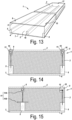
- Fig. 11 shows, in front view, a cross section along line III-III in Fig. 1 of an alternative embodiment of a construction element 1, wherein the construction element 1 is provided with a third recess 17 through a part of the thickness of the core of insulation material 2, wherein the third recess 17 is situated above a third supporting beam 18, wherein the thickness of the core of insulation material 2 is greater than the height of the third supporting beam 18 along at least a part of the length of the construction element, wherein insulation material of the core of insulation material 2 is situated above the third supporting beam 18 along at least a part of the - and preferably along the entire - length of the third supporting beam, wherein insulation material of the core of insulation material 2 is situated next to the third supporting beam 18 along at least a part of the - and preferably along the entire - length of the third supporting beam 18.
- the third recess 17 is provided with an element 11 to which a hoisting means may be attached, which is anchored to the third supporting beam 18 situated underneath.
- the elements 11 present to which a hoisting means may be attached are all of a different type, in particular a hook, a lifting sling and a pivoting lifting eye.
- the pivoting lifting eye 11 is shown in the upward position, the same way it would during hoisting of the construction element 1.
- the pivoting lifting eye 11 in the upward position does not protrude beyond the top surface 3 of the construction element 1, although this is obviously possible and often even desirable.
- the embodiment in Fig. 11 shows different elements 11 to demonstrate the fact that different types of such elements can be used in the context of the invention. However, it is preferred to use only one type of such an element in one and the same construction element according to the invention, without this characteristic feature being essential to the invention.
- a construction element according to the invention to comprise different types of such an element.
- the third recess is situated above the first supporting beam 5 or the second supporting beam 6, there preferably being insulation material of the core of insulation material 2 present between the third recess 17 and the supporting beam situated underneath.
- Fig. 12 shows, in perspective, an embodiment of a construction element 1 according to the invention, wherein there is a local first recess 9 above the first supporting beam 5, a local second recess 15 above the second supporting beam 6, and a third supporting beam 18.
- Fig. 13 shows, also in perspective, a preferred embodiment of a construction element 1 according to the invention, wherein there is a local first recess 9 above the first supporting beam 5, a local second recess 15 above the second supporting beam 6, and a local third recess 17 above the third supporting beam 18.
- Each of the aforementioned recesses 9, 15, 17 is provided with an element, not visible in the figure, to which a hoisting means may be attached.
- the aforementioned elements are non-collinear, in other words they are not aligned.
- the leftmost element and the rightmost element are situated on the same longitudinal end - which is understood to be the same half along the longitudinal direction of the construction element 1, viewed in top view - of the construction element 1, and the central element is on the longitudinal end opposite thereto.
- the distance between the centre of gravity of the largest possible convex polygon, formed by the at least three non-collinear elements to which a hoisting means may be attached, and the centre of gravity of the plane defined by the edges of the construction element 1, is less than 50%, preferably less than 30%, still more preferably less than 10%, of the width B of the construction element 1.
- Fig. 16 for the case where there are four elements 11.
- Fig. 14 shows, in front view, a cross section along line III-III in Fig. 1 of an alternative embodiment of a construction element 1, wherein the first recess 9 and the second recess 15 are covered in a watertight manner by means of a cover means 19, such as a self-adhesive patch, a roof screen or a cover.
- a cover means 19 such as a self-adhesive patch, a roof screen or a cover.
- an element 11 to which a hoisting means may be attached is present in the first recess 9 and in the second recess 15.
- the elements 11 preferably do not protrude beyond the top surface 3 of the construction element 1.
- Fig. 15 shows, also in front view, a cross section along line III-III in Fig. 1 of an alternative embodiment of the construction element 1, wherein the element 11 which is anchored to the first supporting beam 5 consists of several parts 11A, 11B, wherein the several parts are not necessarily made of the same material.
- the first part of the element 11A is anchored to the second part of the element 11B, possibly also to the first supporting beam 5 situated underneath, and the second part of the element 11B is anchored to the first supporting beam 5 situated underneath.
- the first supporting beam 5 consists of several parts, with at least the second part of the element 11B serving as a connection between successive parts of the first supporting beam 5.
- the element 11 in the second recess 15 is a pivoting lifting eye in the downward position, and the element 11 is completely under the top surface 3 of the construction element 1.
- Fig. 16 shows, in top view, a preferred embodiment of a construction element 1 according to the invention, wherein the construction element 1 is provided with a first supporting beam 5 having a local first recess 9 and a local first additional recess 14 above it, and a second supporting beam 6 having a local second recess 15 and a local second additional recess 20 above it.
- a hoisting means may be attached in each recess 9, 14, 15, 20, wherein the element 11 is anchored to the supporting beam 5, 6 situated underneath.
- the centre of gravity Z of the largest possible convex polygon, formed by the elements 11 to which a hoisting means may be attached, and the centre of gravity G of the plane defined by the edges of the construction element 1 have been visualized.
- the distance between the two centres of gravity Z, G is less than 50%, preferably less than 30%, even more preferably less than 10%, of the width B of the construction element 1. This has the advantage that the construction element 1 can be hoisted in a very stable manner.
- the first supporting beam 5, the second supporting beam 6, and the optional third supporting beam 18 do not necessarily have the same dimensions, nor are they made of the same type of material. However, on the basis of technical stock-keeping considerations, it is preferred if the supporting beams are identical, or virtually identical.
- Fig. 17 shows a construction element according to embodiments of the invention.
- Figs. 18, 19 and 20 show details of the construction element from Fig. 17 , according to views XVIII-XVIII, XIX-XIX and XX-XX, respectively, from Fig. 17 .
- the construction element from Fig. 17 is a roof element.
- the roof element from Fig. 17 is configured such that a gutter overhang and an end face overhang can easily be arranged thereon.
- Providing roof elements in order to attach only a gutter overhang or only an end face overhang thereto also fall within the scope of the invention.
- the roof element comprises a core of insulation material 2, between a baseplate 7 and a top panel 8.
- a first supporting beam 5 and a second supporting beam 6 are attached to the baseplate 7 and extend in longitudinal direction of the roof element.
- the thickness of the core of insulation material 2 is greater than the height D1 of the first supporting beam 5 and of the second supporting beam 6.
- insulation material of the core of insulation material 2 is situated above the first supporting beam 5 and above the second supporting beam 6.
- insulation material of the core of insulation material 2 is provided on both sides of both the first supporting beam 5 and the second supporting beam 6, insulation material of the core of insulation material 2 is provided.
- a first recess 9 is provided through a part of the thickness of the core of insulation material 2. This first recess 9 is situated parallel to and above a part of the length of the first supporting beam 5. The first recess 9 extends up to the top surface 3 of the roof element. The first recess 9 extends up to an edge of the core of insulation material 2. The first recess 9 runs as far as on the first supporting beam 5.
- the first supporting beam 5 has a height D2 which is smaller than the height D1 of the first supporting beam 5 outside the recess.
- a beam 25 (shown in Fig. 17 before its fitting into the first recess 9) may be fitted in the first recess 9 by means of screws 30 so as to make contact with and be attached to the first supporting beam 5.
- the beam 25 and the first recess 9 are dimensioned such that the beam 25 protrudes from the core of insulation material 2 at the front, and therefore from the roof element, so that a gutter overhang can be attached to the beam 25.
- the beam 25 and the first recess 9 are dimensioned so that the top side of the fitted beam 25 is situated in the top surface of the roof element.
- first recess and a similar beam may be provided on a second supporting beam 6, so that a gutter overhang can be attached to two parallel beams.
- the roof element from Fig. 17 also comprises a recess 27 in the core of insulation material 2 and perpendicular to the longitudinal direction of the first supporting beam 5.
- the recess 27 runs along the first supporting beam 5 and the second supporting beam 6.
- the recess 27 extends up to an edge of the core of insulation material 2.
- the recess 27 runs as far as on the first supporting beam 5 and the second supporting beam 6, which are both configured to be less high in the recess 27 than outside of it (height D1 outside the recess, height D2 in the recess). Both the first supporting beam 5 and the second supporting beam 6 are thus less high at the recess 27 than outside the recess 27.
- a lateral beam 29 may be attached in the recess 27 so as to make contact with and to the first supporting beam 5, and so as to make contact with and to the second supporting beam 6, by means of screws 30. After fitting, the lateral beam 29 protrudes beyond the edge of the core of insulation material 2. In the example, the top side of the fitted lateral beam 29 is situated in the top surface of the construction element. The lateral beam 29 makes it possible to attach an end face overhang to the roof element.
- a second lateral beam may be attached in a recess on the first supporting beam and on the second supporting beam in a different longitudinal position of the roof element in order to fit an end face overhang to both lateral beams.
- Fig. 17 shows the beam 25 and the lateral beam 29 before being fitted in the roof element.
- the invention also relates to one or more of the following numbered items:
Landscapes
- Engineering & Computer Science (AREA)
- Architecture (AREA)
- Civil Engineering (AREA)
- Structural Engineering (AREA)
- Physics & Mathematics (AREA)
- Electromagnetism (AREA)
- Acoustics & Sound (AREA)
- Building Environments (AREA)
Applications Claiming Priority (2)
| Application Number | Priority Date | Filing Date | Title |
|---|---|---|---|
| BE20236047A BE1032261B1 (nl) | 2023-12-22 | 2023-12-22 | Bouwelement |
| BE20245722A BE1032194B1 (nl) | 2023-12-22 | 2024-10-24 | Bouwelement |
Publications (2)
| Publication Number | Publication Date |
|---|---|
| EP4575120A1 true EP4575120A1 (fr) | 2025-06-25 |
| EP4575120B1 EP4575120B1 (fr) | 2026-04-01 |
Family
ID=93743762
Family Applications (1)
| Application Number | Title | Priority Date | Filing Date |
|---|---|---|---|
| EP24216523.1A Active EP4575120B1 (fr) | 2023-12-22 | 2024-11-29 | Élément de construction |
Country Status (1)
| Country | Link |
|---|---|
| EP (1) | EP4575120B1 (fr) |
Citations (9)
| Publication number | Priority date | Publication date | Assignee | Title |
|---|---|---|---|---|
| DE4101234A1 (de) * | 1990-02-10 | 1991-08-14 | Eugen Gonon | Unterdach-waermedaemmelement |
| JPH08277596A (ja) * | 1995-04-05 | 1996-10-22 | Misawa Homes Co Ltd | パネルを主体とした屋根構造、パネルおよび通気方法 |
| EP0775787A1 (fr) | 1995-11-21 | 1997-05-28 | Unidek Bouwelementen b.v. | Toit pour bâtiment |
| DE20016828U1 (de) * | 2000-09-29 | 2001-04-12 | Thieringer, Werner, 78662 Bösingen | Element zur Herstellung von Gebäudedächern, Gebäudedecken und Gebäudewänden |
| EP2141299A2 (fr) | 2008-07-04 | 2010-01-06 | Unidek B.V. | Panneau en sandwich et son procédé de production |
| EP2273024A2 (fr) | 2009-07-09 | 2011-01-12 | Unilin BVBA | Elément de construction et construction de toiture |
| FR2989704A1 (fr) * | 2012-04-24 | 2013-10-25 | Unilin Bvba | Elements de construction et construction de toiture |
| NL2022483B1 (nl) | 2019-01-31 | 2020-08-18 | Isobouw Systems Bv | Dakelement |
| AU2021105142A4 (en) * | 2021-08-09 | 2021-10-07 | Trad, Betros MR | Prefabricated panelised skylight |
-
2024
- 2024-11-29 EP EP24216523.1A patent/EP4575120B1/fr active Active
Patent Citations (10)
| Publication number | Priority date | Publication date | Assignee | Title |
|---|---|---|---|---|
| DE4101234A1 (de) * | 1990-02-10 | 1991-08-14 | Eugen Gonon | Unterdach-waermedaemmelement |
| JPH08277596A (ja) * | 1995-04-05 | 1996-10-22 | Misawa Homes Co Ltd | パネルを主体とした屋根構造、パネルおよび通気方法 |
| EP0775787A1 (fr) | 1995-11-21 | 1997-05-28 | Unidek Bouwelementen b.v. | Toit pour bâtiment |
| DE20016828U1 (de) * | 2000-09-29 | 2001-04-12 | Thieringer, Werner, 78662 Bösingen | Element zur Herstellung von Gebäudedächern, Gebäudedecken und Gebäudewänden |
| EP2141299A2 (fr) | 2008-07-04 | 2010-01-06 | Unidek B.V. | Panneau en sandwich et son procédé de production |
| EP2273024A2 (fr) | 2009-07-09 | 2011-01-12 | Unilin BVBA | Elément de construction et construction de toiture |
| EP2273024B1 (fr) * | 2009-07-09 | 2013-01-02 | Unilin BVBA | Elément de construction et construction de toiture |
| FR2989704A1 (fr) * | 2012-04-24 | 2013-10-25 | Unilin Bvba | Elements de construction et construction de toiture |
| NL2022483B1 (nl) | 2019-01-31 | 2020-08-18 | Isobouw Systems Bv | Dakelement |
| AU2021105142A4 (en) * | 2021-08-09 | 2021-10-07 | Trad, Betros MR | Prefabricated panelised skylight |
Also Published As
| Publication number | Publication date |
|---|---|
| EP4575120B1 (fr) | 2026-04-01 |
Similar Documents
| Publication | Publication Date | Title |
|---|---|---|
| EP1203125B1 (fr) | Systeme de construction sans charpente et procede pour construire un batiment | |
| US6263628B1 (en) | Load bearing building component and wall assembly method | |
| US5377470A (en) | Modular insulating wall panel system | |
| US6418686B1 (en) | Insulated asymmetrical directional force resistant building panel with symmetrical joinery, integral shear resistance connector and thermal break | |
| US4641468A (en) | Panel structure and building structure made therefrom | |
| US4000594A (en) | Building construction member | |
| US11840836B2 (en) | Structural wall panel system | |
| GB2415714A (en) | Insulated timber frame building panel | |
| WO1992017662A1 (fr) | Systeme de construction | |
| CN101111428A (zh) | 房屋结构、船、建筑物以及用于构造房屋结构的方法 | |
| US20240084593A1 (en) | Structual Wall Panel System | |
| EP2141299A2 (fr) | Panneau en sandwich et son procédé de production | |
| EP0260435B1 (fr) | Panneau de construction composite | |
| EP4575120B1 (fr) | Élément de construction | |
| EP0110849A1 (fr) | Panneau formant une surface | |
| US4848053A (en) | Building construction assembly including a laminated support beam for a glazed structure | |
| WO2000034599A1 (fr) | Poutrelle en i de faible poids et module de construction de faible poids | |
| BE1032194B1 (nl) | Bouwelement | |
| EP1536077B1 (fr) | Procédé de construction d'un bâtiment, ce bâtiment, et élément de mur pour ceux-ci | |
| BE1027821B1 (nl) | Beschot voor het met wanden bekleden van een houten geraamte van een gebouw en werkwijze voor het aanbrengen van zulk beschot op een houten geraamte | |
| EP3529444B1 (fr) | Structure de cloisonnement de pièce résistante à l'effraction et procédé associé à celle-ci | |
| WO2004059098A1 (fr) | Panneaux muraux a montage rapide | |
| EP4534771A1 (fr) | Mur de construction | |
| EP1953300B1 (fr) | Agencement pour assemblage d'éléments de construction à base de bois | |
| EP4592467A1 (fr) | Eléments de construction avec matériau isolant |
Legal Events
| Date | Code | Title | Description |
|---|---|---|---|
| PUAI | Public reference made under article 153(3) epc to a published international application that has entered the european phase |
Free format text: ORIGINAL CODE: 0009012 |
|
| STAA | Information on the status of an ep patent application or granted ep patent |
Free format text: STATUS: THE APPLICATION HAS BEEN PUBLISHED |
|
| AK | Designated contracting states |
Kind code of ref document: A1 Designated state(s): AL AT BE BG CH CY CZ DE DK EE ES FI FR GB GR HR HU IE IS IT LI LT LU LV MC ME MK MT NL NO PL PT RO RS SE SI SK SM TR |
|
| STAA | Information on the status of an ep patent application or granted ep patent |
Free format text: STATUS: REQUEST FOR EXAMINATION WAS MADE |
|
| GRAP | Despatch of communication of intention to grant a patent |
Free format text: ORIGINAL CODE: EPIDOSNIGR1 |
|
| STAA | Information on the status of an ep patent application or granted ep patent |
Free format text: STATUS: GRANT OF PATENT IS INTENDED |
|
| P01 | Opt-out of the competence of the unified patent court (upc) registered |
Free format text: CASE NUMBER: UPC_APP_0013221_4575120/2025 Effective date: 20251113 |
|
| 17P | Request for examination filed |
Effective date: 20251124 |
|
| GRAJ | Information related to disapproval of communication of intention to grant by the applicant or resumption of examination proceedings by the epo deleted |
Free format text: ORIGINAL CODE: EPIDOSDIGR1 |
|
| INTG | Intention to grant announced |
Effective date: 20251209 |
|
| STAA | Information on the status of an ep patent application or granted ep patent |
Free format text: STATUS: REQUEST FOR EXAMINATION WAS MADE |
|
| GRAP | Despatch of communication of intention to grant a patent |
Free format text: ORIGINAL CODE: EPIDOSNIGR1 |
|
| STAA | Information on the status of an ep patent application or granted ep patent |
Free format text: STATUS: GRANT OF PATENT IS INTENDED |
|
| INTC | Intention to grant announced (deleted) | ||
| GRAS | Grant fee paid |
Free format text: ORIGINAL CODE: EPIDOSNIGR3 |
|
| INTG | Intention to grant announced |
Effective date: 20260122 |
|
| GRAA | (expected) grant |
Free format text: ORIGINAL CODE: 0009210 |
|
| STAA | Information on the status of an ep patent application or granted ep patent |
Free format text: STATUS: THE PATENT HAS BEEN GRANTED |
|
| AK | Designated contracting states |
Kind code of ref document: B1 Designated state(s): AL AT BE BG CH CY CZ DE DK EE ES FI FR GB GR HR HU IE IS IT LI LT LU LV MC ME MK MT NL NO PL PT RO RS SE SI SK SM TR |
|
| REG | Reference to a national code |
Ref country code: CH Ref legal event code: F10 Free format text: ST27 STATUS EVENT CODE: U-0-0-F10-F00 (AS PROVIDED BY THE NATIONAL OFFICE) Effective date: 20260401 Ref country code: GB Ref legal event code: FG4D |
|
| REG | Reference to a national code |
Ref country code: DE Ref legal event code: R096 Ref document number: 602024003644 Country of ref document: DE |
|
| REG | Reference to a national code |
Ref country code: IE Ref legal event code: FG4D |