EP4575140A1 - Système d'échafaudage de toit temporaire - Google Patents
Système d'échafaudage de toit temporaire Download PDFInfo
- Publication number
- EP4575140A1 EP4575140A1 EP23218166.9A EP23218166A EP4575140A1 EP 4575140 A1 EP4575140 A1 EP 4575140A1 EP 23218166 A EP23218166 A EP 23218166A EP 4575140 A1 EP4575140 A1 EP 4575140A1
- Authority
- EP
- European Patent Office
- Prior art keywords
- columns
- sliding
- scaffolding
- temporary roof
- roof
- Prior art date
- Legal status (The legal status is an assumption and is not a legal conclusion. Google has not performed a legal analysis and makes no representation as to the accuracy of the status listed.)
- Pending
Links
Images


Classifications
-
- E—FIXED CONSTRUCTIONS
- E04—BUILDING
- E04G—SCAFFOLDING; FORMS; SHUTTERING; BUILDING IMPLEMENTS OR AIDS, OR THEIR USE; HANDLING BUILDING MATERIALS ON THE SITE; REPAIRING, BREAKING-UP OR OTHER WORK ON EXISTING BUILDINGS
- E04G21/00—Preparing, conveying, or working-up building materials or building elements in situ; Other devices or measures for constructional work
- E04G21/24—Safety or protective measures preventing damage to building parts or finishing work during construction
- E04G21/28—Safety or protective measures preventing damage to building parts or finishing work during construction against unfavourable weather influence
-
- E—FIXED CONSTRUCTIONS
- E04—BUILDING
- E04G—SCAFFOLDING; FORMS; SHUTTERING; BUILDING IMPLEMENTS OR AIDS, OR THEIR USE; HANDLING BUILDING MATERIALS ON THE SITE; REPAIRING, BREAKING-UP OR OTHER WORK ON EXISTING BUILDINGS
- E04G21/00—Preparing, conveying, or working-up building materials or building elements in situ; Other devices or measures for constructional work
- E04G21/24—Safety or protective measures preventing damage to building parts or finishing work during construction
- E04G21/242—Safety or protective measures preventing damage to building parts or finishing work during construction for temporarily covering the whole worksite, e.g. building, trench
Definitions
- the present invention relates to a temporary roof scaffolding system for protecting associated buildings, said system comprising: a temporary roof, a plurality of scaffolding elements being arranged next to each other and above each other to form at least one scaffolding bay, a plurality of columns, such as masts, a plurality of sliding arrangements to enable movement in the elevation direction of the columns, a plurality of locking means for stopping the columns from sliding in a downwards direction, wherein the roof is attached to the upper end of the columns, and wherein the sliding arrangements is arranged on, in or in connection with, the scaffolding bay.
- the invention relates to a method for raising the height of a temporary roof scaffolding system, wherein said method comprises the steps of: providing a scaffolding system, raising the columns in an upwards direction via the sliding means and increasing the distance between the lower end of the column and the ground, stopping the raising of the columns, positioning locking means in the sliding arrangement for stopping the columns from sliding down in a downwards direction.
- the temporary roof is built in the desired end-height from the start. This provides a temporary roof that actually does not protect the building underneath the roof in the start-stage of the construction process, since the building is too low to be protected by the roof, as the roof is too high to provide any protection, such as weather protection.
- an improved system and method preferably an efficient and reliable system, for regulating the height of a temporary roof would be advantageous, and in particular an easy, resistant, mechanical strong, economical, sustainable system and method would be advantageous.
- a temporary roof scaffolding system for protecting associated buildings comprising:
- temporary roof scaffolding system may be understood as a system, wherein a temporary roof is arranged in connection with a scaffolding.
- sliding may be understood as moving, elevating, supporting and/or the like.
- the word “sliding” must be understood with a very broad understanding and should not be limiting to the invention.
- elevation direction may be understood as an up- and down direction and/or vertical direction.
- the invention is particularly, but not exclusively, advantageous for providing a temporary roof scaffolding system, wherein the height of the system is quickly and easily regulated.
- the system is extremely uncomplicated to establish, easy to maintain, easy to adjust, easy to take down, easy to transport, and easy to reuse multiple times.
- the invention provides a temporary roof scaffolding system with the potential of being free-standing, detached from the building and non-founded to the ground.
- the roof comprises two horizontal beams, and wherein the upper ends of the columns are attached to the one of the two horizontal beams.
- the columns when being arranged in the sliding arrangement, are only affected by gravity if not locked from sliding in a downwards direction by locking means, such as the columns are not affected by any force except the gravity.
- the embodiment is particularly, but not exclusively, advantageous for providing a simple system, wherein the sliding of the columns in the sliding arrangement is not dependent on any arrangement providing a force.
- the columns are adapted for, during a building process of the associated building, being raised in the elevation direction, wherein the distance between the lower end of the column and the ground increases.
- the embodiment is particularly, but not exclusively, advantageous for providing a system being "self-climbing/-moving", meaning that the columns are adapted to be climbing/moving in an upwards direction.
- the need of extremely and vastly long columns are thereby eliminated, since the columns are climbing/moving up at the system and the length of the columns is thereby kept to a minimum.
- the roof is comprising a plurality of roof modules adapted for being arranged next to each other.
- the embodiment is particularly, but not exclusively, advantageous for providing a system wherein the roof can be raised one module at a time, thereby decreasing the load to be raised when raising the roof.
- the sliding arrangements comprises one or more of:
- the embodiment is particularly, but not exclusively, advantageous for providing reliable and effective sliding arrangement, being easy to incorporate and/or integrate in a scaffolding system.
- the locking means are one or more of:
- the embodiment is particularly, but not exclusively, advantageous for providing a system with easily accessible locking means, and even more easy employment and deployment of the locking means.
- the scaffolding elements are detached from the associated building.
- the embodiment is particularly, but not exclusively, advantageous for providing a temporary roof system that can stand freely on its own, without falling or tilting, and thereby not necessarily needing to be attached/fixed/founded to the associated building and/or the ground.
- the columns each comprise four corner bars, preferably being interconnected by transverse bars, and preferably wherein the columns form a quadrilateral cross-section.
- the embodiment is particularly, but not exclusively, advantageous for providing a mechanical strong and reliable column, such as a mast.
- the corner bars are adapted to slide on the sliding arrangements.
- each sliding arrangement comprises at least four protruding rods, each rod being:
- the embodiment is particularly, but not exclusively, advantageous for providing a sliding arrangement adapted for being simply integrated in a scaffolding system and further being both a simple arrangement and an exceptionally reliable arrangement.
- each sliding arrangement comprises at least eight protruding rods, wherein the eight rods are adapted to form four support arrangements, each support arrangement comprising the second end of two rods for providing support and allow sliding of a column, preferably wherein the support arrangements are arranged to support two sides of a corner of the column.
- the embodiment is particularly, but not exclusively, advantageous for providing an even more mechanically strong and reliable sliding arrangement.
- the system is adapted to raise a roof of the scaffolding system during a construction process, wherein the distance between the roof and the ground increases.
- the embodiment is particularly, but not exclusively, advantageous for providing a system being "self-climbing/-moving", meaning that the roof being attached to the columns, is adapted to be climbing/moving in an upwards direction.
- the need of extremely and vastly long columns is thereby eliminated, since the roof and the columns are climbing/moving up at the system and the length of the columns is thereby decreased to a minimum.
- the invention further relates to a method for raising the height of a temporary roof scaffolding system, wherein said method comprises the steps of:
- the second aspect of the invention is particularly, but not exclusively, advantageous for providing a method for raising the height of a temporary roof scaffolding system, wherein the height of the system is quickly and easily regulated.
- the method of the invention provides a temporary roof that can be regulated in height potentially with only manpower, and no need of any external forces.
- the regulation may also, if desired, be performed by for example a crane, an engine, a motor and/or the like.
- the columns are attached to a temporary roof of the system.
- the embodiment is particularly, but not exclusively, advantageous for providing a method for raising a temporary roof system that can be regulated in height potentially with only manpower, and no need for any external forces.
- the regulation may also, if desired, be performed by such as a crane, an engine, a motor and/or the like.
- the embodiment is particularly, but not exclusively, advantageous for providing a system wherein the roof can be raised one module at a time, thereby decreasing the load to be raised when raising the roof.
- more scaffolding elements such as bays, are provided along the raising of the columns and/or more sliding arrangements are provided along the raising of the columns.
- the embodiment is particularly, but not exclusively, advantageous for providing a stabile system for raising the masts in the height / elevation direction.
- the steps of raising and positioning locking means is performed and/or repeated when the height of the associated building has reached the maximum height for being arranged underneath the temporary roof of the scaffolding system, wherein the height of the system is raised in relation to construction of the building.
- the embodiment is particularly, but not exclusively, advantageous for providing a method with easy performance of the roof raising and even more easy employment and deployment of the locking means.
- the first and second aspect of the present invention may each be combined with any of the other aspects.
- Embodiments from the system/product should be seen as applicable to the method, and embodiments from the method should be seen as applicable for the product/system.
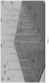
- FIG 1 illustrates a 3D drawing of scaffolding elements 300 and columns 400.
- the plurality of scaffolding elements 300 are in FIG. 1 illustrated as scaffold bays being arranged next to each other and above each other to form at least one scaffolding structure.
- the plurality of columns 400 in FIG. 1 are masts being arranged in a plurality of sliding arrangements 500 for enabling movement in the elevation direction of the masts 400.
- the sliding arrangements 500 are in FIG. 1 arranged as an integrated part of the scaffolding bays 300.
- the sliding arrangements 500 can be arranged on, in or in connection with, the scaffolding elements 300.
- the columns 400 when being arranged in the sliding arrangement 500, are only affected by gravity if not locked from sliding in a downwards direction by locking means, such that the columns 400 are not affected by any force except gravity.
- the masts have a distance D to the ground being 0, since the masts 400 are supported on the ground due to gravity. In FIG. 1 there are no locking means arranged in the system.
- FIG 2 illustrates a 3D drawing of two beams 250 attached to columns.
- the system is comparable to the system illustrated in FIG. 1 , though wherein the roof 200 comprises two horizontal beams 250, and wherein the upper ends 410 of the columns are attached to the one of the two horizontal beams 250.
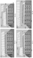
- FIG 3 illustrates a 3D drawing of a temporary roof 200 on a scaffolding system 100 and a building B being under construction underneath the temporary roof 200.
- the temporary roof scaffolding system 100 has the purpose of protecting the associated buildings B, and said system comprising:
- scaffolding elements 300 are detached from the associated building B (not directly illustrated).
- the columns 400 are adapted for, during a building process of the associated building B, being raised in the elevation direction, wherein the distance D between the lower end 420 of the column 400 and the ground increases.
- the masts 400 have a distance D to the ground being above 0, since the masts are not supported on the ground, but supported and locked by locking means.
- the temporary roof 200 has therefore been raised in an upwards direction, and thereby has increased the height.
- FIG 4 illustrates a 3D drawing of a raised temporary roof 200.
- the masts 400 have a distance D to the ground being even higher than the distance illustrated in FIG. 3 .
- the temporary roof 200 has therefore been raised even further in an upwards direction, and thereby has increased the height during a construction process of a building B underneath the temporary roof 200.
- scaffolding elements 300 such as bays
- sliding arrangements 500 are provided along the raising of the columns 400.
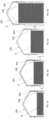
- FIG 5a-d illustrates in 3D drawing the steps of raising a temporary roof 200.
- the temporary roof of the scaffolding system 100 illustrated is comprising a plurality of roof modules 210 adapted for being arranged next to each other and thereby forming a coherent temporary roof 200.
- the figures 5a-d illustrate a method for raising the height of a temporary roof 200 scaffolding system 100, wherein said method comprises the steps of:
- Figure 6a-d illustrate the steps of raising a temporary roof 200 during a construction process.
- the building may raise in height. Therefore, also the temporary roof 200 may raise in height.
- the raising and positioning of locking means is performed and/or repeated when the height of the associated building B has reached the maximum height for being arranged underneath the temporary roof 200 of the scaffolding system 100.
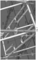
- FIG 7 illustrates a sliding arrangement without a column 400, being a mast, wherein each sliding arrangement 500 comprises at least four protruding rods 550, each rod being:
- said rods 550 are arranged to at least substantially center a column 400 in the sliding arrangement 500.
- each sliding arrangement comprises eight protruding rods 550, wherein the eight rods are adapted to form four support arrangements 530, each support arrangement 530 comprising the second end 552 of two rods for providing support and allow sliding of a column 400.
- the sliding arrangement 500 is illustrated as being an integrated part of the scaffolding 300, however within the invention it could also be arranged otherwise in the system 100.
- FIG 8 illustrates a sliding arrangement 500 about to slide/support a column 400, being a mast, wherein the columns 400 each comprise four corner bars 430, preferably being interconnected by transverse bars 440, and preferably wherein the columns 400 form a quadrilateral cross-section.
- the corner bars 430 are adapted to be supported and/or slide on the sliding arrangements 500.
- FIG 9 illustrates a sliding arrangement 500 with a column 400, being a mast, as illustrated the support arrangements 530 are arranged to support two sides of a corner 430 of the column 400.
Landscapes
- Engineering & Computer Science (AREA)
- Architecture (AREA)
- Mechanical Engineering (AREA)
- Civil Engineering (AREA)
- Structural Engineering (AREA)
- Movable Scaffolding (AREA)
- Conveying And Assembling Of Building Elements In Situ (AREA)
Priority Applications (2)
| Application Number | Priority Date | Filing Date | Title |
|---|---|---|---|
| EP23218166.9A EP4575140A1 (fr) | 2023-12-19 | 2023-12-19 | Système d'échafaudage de toit temporaire |
| PCT/EP2024/086836 WO2025132385A1 (fr) | 2023-12-19 | 2024-12-17 | Système d'échafaudage de toit temporaire |
Applications Claiming Priority (1)
| Application Number | Priority Date | Filing Date | Title |
|---|---|---|---|
| EP23218166.9A EP4575140A1 (fr) | 2023-12-19 | 2023-12-19 | Système d'échafaudage de toit temporaire |
Publications (1)
| Publication Number | Publication Date |
|---|---|
| EP4575140A1 true EP4575140A1 (fr) | 2025-06-25 |
Family
ID=89430454
Family Applications (1)
| Application Number | Title | Priority Date | Filing Date |
|---|---|---|---|
| EP23218166.9A Pending EP4575140A1 (fr) | 2023-12-19 | 2023-12-19 | Système d'échafaudage de toit temporaire |
Country Status (2)
| Country | Link |
|---|---|
| EP (1) | EP4575140A1 (fr) |
| WO (1) | WO2025132385A1 (fr) |
Citations (4)
| Publication number | Priority date | Publication date | Assignee | Title |
|---|---|---|---|---|
| GB2250731A (en) * | 1990-08-09 | 1992-06-17 | Mitsubishi Heavy Ind Ltd | Apparatus and method of constructing a building |
| EP0487516B1 (fr) * | 1988-09-05 | 1995-01-18 | Ohbayashi Corporation | Appareil et méthode de construction |
| KR20150053015A (ko) * | 2013-11-07 | 2015-05-15 | 지에스건설 주식회사 | 원자력 발전소의 철골구조를 이용한 전천후 가설 지붕 시스템 |
| CN111364366A (zh) * | 2020-03-24 | 2020-07-03 | 浙江大学宁波理工学院 | 跨越铁路的高架桥施工时用的铰接式防护棚架及搭设方法 |
-
2023
- 2023-12-19 EP EP23218166.9A patent/EP4575140A1/fr active Pending
-
2024
- 2024-12-17 WO PCT/EP2024/086836 patent/WO2025132385A1/fr active Pending
Patent Citations (4)
| Publication number | Priority date | Publication date | Assignee | Title |
|---|---|---|---|---|
| EP0487516B1 (fr) * | 1988-09-05 | 1995-01-18 | Ohbayashi Corporation | Appareil et méthode de construction |
| GB2250731A (en) * | 1990-08-09 | 1992-06-17 | Mitsubishi Heavy Ind Ltd | Apparatus and method of constructing a building |
| KR20150053015A (ko) * | 2013-11-07 | 2015-05-15 | 지에스건설 주식회사 | 원자력 발전소의 철골구조를 이용한 전천후 가설 지붕 시스템 |
| CN111364366A (zh) * | 2020-03-24 | 2020-07-03 | 浙江大学宁波理工学院 | 跨越铁路的高架桥施工时用的铰接式防护棚架及搭设方法 |
Also Published As
| Publication number | Publication date |
|---|---|
| WO2025132385A1 (fr) | 2025-06-26 |
Similar Documents
| Publication | Publication Date | Title |
|---|---|---|
| US5577362A (en) | Module construction method in a steel structure building zone | |
| US9580919B2 (en) | Scaffold with scaffolding elements and methods for erection thereof | |
| US11655640B2 (en) | Self-climbing device for vertical and quasi-vertical concrete surfaces and operating method | |
| CA2823814C (fr) | Ensemble de montage et procede pour eriger en sections une tour annulaire pour des generateurs eoliens ou heliostatiques dans une installation de parc eolien | |
| JPH04111829A (ja) | 大スパン屋根の施工法 | |
| CN111527302B (zh) | 用于建造塔的方法、塔段、供应结构以及塔 | |
| CN113348289A (zh) | 多柱式风力涡轮机塔及架设方法 | |
| WO2023126974A1 (fr) | Tour de télécommunication à base de pilier mobile | |
| US20130263549A1 (en) | Safety screen system for steel erection work | |
| EP4575140A1 (fr) | Système d'échafaudage de toit temporaire | |
| KR20150127559A (ko) | 접이식 매단 비계 | |
| EP3714119B1 (fr) | Appareil et procédé de mise à niveau de tour de service public | |
| KR101372294B1 (ko) | 잭 장치를 이용한 기상타워 인상 시공방법 | |
| WO2019151880A1 (fr) | Procédé d'installation de poteaux de ligne électrique en acier | |
| AU2021475713B2 (en) | System for the automated lifting of a hybrid-tower wind turbine and method followed | |
| AU2019201299B2 (en) | System and method for a vertically adjustable tower crane | |
| JP2579715B2 (ja) | 外部式鉄塔組立クレーン | |
| CN213990558U (zh) | 一种可调节式光伏支架 | |
| EP3326959B1 (fr) | Agencement de levage, mât divisé en éléments et procédés de montage, de démontage et de maintenance d'un mât | |
| CN216196480U (zh) | 一种采用贝雷梁结构的高空作业平台 | |
| CN213296082U (zh) | 一种高空作业平台 | |
| CN211923428U (zh) | 高空施工平台 | |
| CN218378382U (zh) | 一种具有高低落差的组装式设备框架 | |
| EP3095921B1 (fr) | Fondation de pylône d'éolienne et procédé de prémontage de pylône d'éolienne | |
| US3393480A (en) | Antenna supporting tower and method of constructing same |
Legal Events
| Date | Code | Title | Description |
|---|---|---|---|
| PUAI | Public reference made under article 153(3) epc to a published international application that has entered the european phase |
Free format text: ORIGINAL CODE: 0009012 |
|
| STAA | Information on the status of an ep patent application or granted ep patent |
Free format text: STATUS: THE APPLICATION HAS BEEN PUBLISHED |
|
| AK | Designated contracting states |
Kind code of ref document: A1 Designated state(s): AL AT BE BG CH CY CZ DE DK EE ES FI FR GB GR HR HU IE IS IT LI LT LU LV MC ME MK MT NL NO PL PT RO RS SE SI SK SM TR |
|
| STAA | Information on the status of an ep patent application or granted ep patent |
Free format text: STATUS: THE APPLICATION IS DEEMED TO BE WITHDRAWN |