EP4575153A1 - Verriegelung für ein schiebeverschlusselement und verschlusssystem damit - Google Patents
Verriegelung für ein schiebeverschlusselement und verschlusssystem damit Download PDFInfo
- Publication number
- EP4575153A1 EP4575153A1 EP23218254.3A EP23218254A EP4575153A1 EP 4575153 A1 EP4575153 A1 EP 4575153A1 EP 23218254 A EP23218254 A EP 23218254A EP 4575153 A1 EP4575153 A1 EP 4575153A1
- Authority
- EP
- European Patent Office
- Prior art keywords
- locking
- latch bolt
- lock
- frame
- gear member
- Prior art date
- Legal status (The legal status is an assumption and is not a legal conclusion. Google has not performed a legal analysis and makes no representation as to the accuracy of the status listed.)
- Pending
Links
Images


Classifications
-
- E—FIXED CONSTRUCTIONS
- E05—LOCKS; KEYS; WINDOW OR DOOR FITTINGS; SAFES
- E05B—LOCKS; ACCESSORIES THEREFOR; HANDCUFFS
- E05B65/00—Locks or fastenings for special use
- E05B65/08—Locks or fastenings for special use for sliding wings
- E05B65/0835—Locks or fastenings for special use for sliding wings the bolts pivoting about an axis parallel to the wings
- E05B65/0841—Locks or fastenings for special use for sliding wings the bolts pivoting about an axis parallel to the wings and parallel to the sliding direction of the wings
-
- E—FIXED CONSTRUCTIONS
- E05—LOCKS; KEYS; WINDOW OR DOOR FITTINGS; SAFES
- E05B—LOCKS; ACCESSORIES THEREFOR; HANDCUFFS
- E05B65/00—Locks or fastenings for special use
- E05B65/0007—Locks or fastenings for special use for gates
Definitions
- the present invention relates to a lock for a sliding closure member.
- the present invention further relates to closure system comprising such a lock.
- EP 1 336 708 A1 discloses lock for a slidable closure member.
- the lock comprises: a frame; a latch bolt having a shaft part extending along a first direction and at least one laterally projecting wing, the latch bolt being rotatably mounted on the frame about a rotation axis extending in the first direction between a latching position and an unlatching position; a latch bolt actuating mechanism configured to rotate the latch bolt from its latching position to its unlatching position; and a locking mechanism.
- the latch bolt actuating mechanism comprises: a spindle follower rotatably mounted on the frame about a further rotation axis between a rest position and an actuated position, wherein the further rotation axis extends in a second direction that forms an angle with respect to the first direction, and a gear member engaging the spindle follower and the latch bolt and being movable between an idle position and an activated position, wherein the gear member is configured to be moved from its idle position to its activated position when the spindle follower is rotated from its rest position to its actuated position thereby rotating the latch bolt from its latching position to its unlatching position.
- the locking mechanism is configured to lock the spindle follower in its rest position and comprises a locking member movably mounted on the frame between a locking position in which the locking member prevents a rotation of the spindle follower from its rest position to its actuated position and an unlocking position in which the locking member does not prevent a rotation of the spindle follower from its rest position to its actuated position.
- the lock disclosed in EP 1 336 708 A1 relies on a two-part spindle follower.
- the spindle follower has a first lever component fixed to the spindle with a biasing member urging the spindle and the handle associated thereto to the rest position.
- the locking member interacts with the first lever to prevent rotation thereof, which rotation would unlatch the latch bolt.
- the spindle follower has a second lever which is coaxial with the first lever about the spindle.
- the second lever interacts with the latch bolt and causes that a rotation of the second lever results in a rotation of the latch bolt.
- a coil spring is interposed between the first lever and the second lever.
- a downside of the known latch is that the latch bolt can be forcibly rotated even when the locking mechanism is locked. More specifically, a person with ill intent can grab the latch bolt shaft (e.g. with pliers) or force an elongated object (e.g. a screw driver) into the latch bolt keep to exert a rotational force on the latch bolt. If this force is high enough to overcome the coil spring force, the latch bolt and second lever are rotated thereby unlatching the lock even though the locking mechanism is locked and prevents a rotation of the first lever.
- a person with ill intent can grab the latch bolt shaft (e.g. with pliers) or force an elongated object (e.g. a screw driver) into the latch bolt keep to exert a rotational force on the latch bolt. If this force is high enough to overcome the coil spring force, the latch bolt and second lever are rotated thereby unlatching the lock even though the locking mechanism is locked and prevents a rotation of the first lever.
- the locking mechanism further comprises a locking element movably mounted on the frame between a locking state in which the locking element prevents a rotation of the gear member from its idle position to its activated position and an unlocking state in which the locking element does not prevent a rotation of the gear member from its idle position to its activated position.
- An embodiment of the present invention is characterised in that the locking element is biased towards its locking state by a predefined biasing force, wherein the lock is self-latching such that a closing motion of the sliding closure member is configured to move the gear member from its idle position to its activated position against the predefined biasing force.
- a self-latching lock i.e. where the lock latches automatically when closing the closure member
- a rigid and immovable locking element when in its locking state, always prevents the rotation of the gear member and latch bolt.
- the predefined biasing force is then set sufficiently high so as to prevent a person with ill intent to forcible rotate the latch bolt and no too high so that the latch bolt rotational force caused by the closing motion of the closure member is sufficient to overcome predefined biasing force.
- an embodiment of the present invention is characterised in that the locking mechanism comprises a biasing member, such as a compression spring, interposed between the frame and the locking element, which biasing member exerts the predefined biasing force onto the locking element.
- a biasing member such as a compression spring
- the locking element can be biased (e.g. manufacture from an elastic material such as spring metal)
- the use of a separate biasing member is advantageous as it allows an accurate control of the predefined biasing force.
- An embodiment of the present invention is characterised in that the locking element is slidable between its locking state and its unlocking state along a third direction and the predefined biasing force is directed along a fourth direction which is angled, in particular by a substantially right angle, with respect to the third direction, the fourth direction preferably being the same as the second direction.
- the motion of the locking element between its locking state and its unlocking state is independent from the motion of the locking element when forced against the predefined biasing force.
- An embodiment of the present invention is characterised in that the locking element is mounted on and co-moving with the locking member.
- An embodiment of the present invention is characterised in that the gear member comprises a lateral projecting protrusion which, when the locking element is in its locking state, engages the locking element.
- Providing an additional lateral projecting protrusion on the gear member firstly enables other parts of the gear member to remain unmodified and to focus on robustly transferring the rotational motion of the spindle follower to the latch bolt. Secondly, when the gear member undergoes a rotational motion, the provision of a laterally projecting protrusion reduces the force exerted by the gear member on the locking element due to the radial distance between the laterally projecting protrusion and the rotation axis.
- the latch bolt actuating mechanism comprises a first biasing member, such as a tension spring, interposed between the frame and the gear member to bias the latch bolt to its latching position.
- a first biasing member such as a tension spring
- an embodiment of the present invention is characterised in that the latch bolt actuating mechanism comprises a second biasing member, such as a compression spring, interposed between the frame and the spindle follower to bias the latch bolt to its latching position.
- a second biasing member such as a compression spring
- biasing members improves the lock robustness and secureness as the latch bolt is automatically rotated to its latching position without requiring user intervention.
- An embodiment of the present invention is characterised in that the gear member and the spindle follower jointly form a bevel gear.
- a bevel gear is convenient way to realize the desired transfer of rotation over an angle, preferably a 90° angle, from the spindle follower to the latch bolt.
- An embodiment of the present invention is characterised in that the gear member is rotatably mounted on the frame about said rotation axis, the gear member preferably being coaxial with the latch bolt.
- a rotatable gear member with a rotation axis in the first direction means that the rotational direction transfer is made between the spindle follower and the gear member thereby avoiding that this transfer still has to occur between the gear member and the latch bolt.
- Having the gear member coaxial with the latch bolt further avoids the need for additional components in the latch bolt actuating mechanism to transfer a rotational motion of the gear member to the latch bolt.
- An embodiment of the present invention is characterised in that the gear member and the latch bolt shaft part have mutually cooperating interlocking means which rotatably lock the gear member and the latch bolt to one another.
- gear member integrally formed with the latch bolt shaft part.
- An embodiment of the present invention is characterised in that the further rotation axis of the spindle follower is substantially perpendicular to the rotation axis of the latch bolt.
- the locking mechanism further comprises a key actuated cylinder mounted on the frame and provided with a rotary driving bit having a free extremity arranged to travel along a circular path along a locking direction and an unlocking direction, opposite to said locking direction, upon actuation of said key actuated cylinder, wherein the locking member has a first engaging portion for engaging the rotary driving bit when the rotary driving bit is rotated in its locking direction to move the locking member from its unlocking position to its locking and a second engaging portion for engaging the rotary driving bit when the rotary driving bit is rotated in its unlocking direction to move the locking member from its unlocking position to its locking position.
- a key-actuated cylinder with a rotary driving bit is a common component of locking mechanisms.
- An embodiment of the present invention is characterised in that the locking member is slidably mounted on the frame between its locking position and its unlocking position, the locking mechanism preferably further comprising a biasing member urging the locking member to either one of its locking position and unlocking position.
- a sliding locking member is more reliable to be used in conjunction with a key-actuated cylinder with a rotary driving bit as opposed to a pivoting locking member.
- a biasing member urging the locking member to either one of its locking position and unlocking position results in a bi-stable locking member. This improves operation and robustness of the lock as intermediate locking member positions are avoided.
- a closure system comprising: a support; a closure member which is slidable with respect to the support between a closed position and an open position; and a lock as described above for locking the slidable closure member in its closed position.
- the closure system includes the lock as described above and thus achieves the same advantages.
- An embodiment of the present invention is characterised in that the lock is mounted on the closure member and the closure system further comprises a latch bolt keep mounted on the support.
- a person desiring to open the closure member thus only has to take hold of the driver of the latch bolt actuating mechanism to unlock the lock (i.e. unlatch the latch bolt) and slide open the closure member.
- substantially includes variations of +/- 10% or less, preferably +/-5% or less, more preferably +/-1 % or less, and more preferably +/-0.1% or less, of the specified condition, in as far as the variations are applicable to function in the disclosed invention. It is to be understood that the term “substantially A” is intended to also include “A”.
- the lock 1 is generally intended to be used for latching and locking a slidable closure member (not shown) to a support (not shown).
- the lock 1 is intended to be mounted against an upright tubular profile of a sliding closure member, e.g. a gate.
- the lock may be intended to be morticed into an upright tubular profile of a sliding closure member.
- the support may be formed by a various elements, e.g. a wall or another movable closure member, however it is commonly formed by a stationary upright tubular profile.
- a bolt keep for example as disclosed in figures 6 to 11 of EP 1 336 708 A1 , is then mounted on or morticed into the support.
- the hollow tubular member is common in outdoor applications (e.g. as part of a fence) and usually has square or rectangular cross-sections with external dimensions of 4 cm, 5 cm or 6 cm (e.g. a rectangular cross-section of 3x6 cm or 4x6 cm).
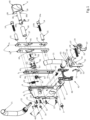
- FIG. 1 shows an exploded view of the lock 1 according to the present invention.
- the lock 1 comprises frame comprising a base plate 8.
- the base plate 8 has on its front side an upstanding edge 9 and on its back side a further upstanding edge 10.
- a front base element 5 is disposed adjacent the front upstanding edge 9.
- the lock 1 has a multi-part front plate 7, having an outer front plate 7a and an inner front plate 7b both having the same outer contour dimension.
- the inner front plate 7b contacts the front base element 5.
- a cover box (not shown) may be provided so that the base plate 8 can be slid completely therein with a free edge of the cover box engaging a peripheral edge of the inner front plate 7b.
- the front base element 5 and the front plates 7a, 7b are fixed to the upstanding edge 9 by means of bolts 12.
- the lock 1 is fixed to the upright tubular member of the closure member by means of bolts 14, sleeves 15 and nuts 3. More specifically, the nuts 3 engage an inner side of the front upstanding edge 9 and protrude through the front base element 5 and the front plates 7a, 7b.
- the bolts 14 are placed through the upright tubular member with their threaded part 14b engaging in the nuts 3 and their head 14a engaging a wall of the upright tubular member.
- the sleeves 15 are disposed around the bolts 14 to reduce water infiltration in the lock 1.
- the lock 1 comprises a rotatable latch bolt 4 which is able to rotate about a rotation axis 37.
- the latch bolt 4 comprises a shaft portion 38 and at least one laterally projecting lock wing 39.
- the illustrated bolt 4 comprises more particularly two lock wings 39 which project in opposite directions.
- the two lock wings 39 are formed by a head portion 40 of the latch bolt 4 which is fixed onto the distal extremity 38a of the shaft portion 38.
- the shaft portion 38 (like the bolts 14) extends through the upright tubular support of the closure member so that a sleeve 90 is disposed around the shaft 38 to reduce water infiltration.
- the proximal extremity 38b of the shaft 38 is received inside a base sleeve 91 which is rotatable mounted on the frame.
- the angular orientation of the head portion 40 with respect to the base sleeve 91 is fixed by means of a set screw 41 screwed through one of the holes 92 in the base sleeve 91.
- the base sleeve 91 is secured to the frame by the collar 45 and ring 93 which are received in a recess 44 in the inner cover plate 7b.
- This recess 44 is larger than the recess 95 provided in the outer cover plate 7a and the recess 43 in the front base element 5.
- the collar 45 and ring 93 are thus wedged between the front base element 5 and the outer cover plate 7a. In this way, the base sleeve 91 and latch bolt 4 can rotate in the openings 43, 44, 95 and is strongly secured between front base element 5 and the outer cover plate 7a by means of the collar 45. If desired, the collar 45 could be widened thereby alleviating the need for an additional ring 93.
- a gear member 31 is mounted on base sleeve 91 of the latch bolt 4. This gear member 31 is rotatable locked to the base sleeve 91.
- the base sleeve 91 has a grooved part 97 and the gear member 31 has a corresponding ridged part 98 which fit together to interlock the gear member 31 and the base sleeve 91.
- An additional securing bolt 96 is provided to securely fasten the gear member 31 to the base sleeve 91. In this manner, the gear member 31 is co-axial with the latch bolt 4 and is rotatable about the rotation axis 37.
- a tension spring 32 is arranged between the gear member 31 and the base plate 8.
- the base plate 8 is provided with a notch 2 in which a first end of the tension spring 32 is disposed and the gear member 31 is provided with a protrusion 6 about which the second end of the tension spring 32 is disposed.
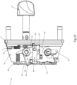
- the tension spring 32 urges the gear member 31 to its idle state (which corresponds to the unlatched state of the latch bolt 4) shown in figures 2A and 2B .
- the lock 1 further comprises handles 21.
- these handles 21 are mounted onto a square spindle 22 onto which they are fixed by means of set screws 23.
- the handles 21 may be replaced with other suitable drivers, e.g. knobs, buttons, etc.
- the cover box (not shown) is naturally provided with aligned openings wherein the door handles 21 and the key operated cylinder 17 can be mounted.
- the spindle 22 is inserted in the hole of a spindle follower 24.
- This hole has a square cross-section corresponding to the cross-section of the spindle 22 so that the spindle follower 24 can be rotated by means of the handles 21.
- Both the spindle follower 24 and the spindle 22 can thus rotate on the frame according to a rotation axis 25.
- this rotation axis 25 forms an angle with the direction into which the latch bolt 4 projects out of the frame or with the rotation axis 37 of the latch bolt 4. Both rotation axes 25 and 37 preferably form an angle of about 90°.
- the latch bolt actuating mechanism which enables to convert a rotation of the handles 21 about their rotation axis 25 into a corresponding rotation of the latch bolt 4 about its rotation axis 37 comprises the spindle follower 24 which comprises a plate-shaped portion 26 acting as a latch bolt lever.
- the plate-shaped portion 26 and the spindle follower 24 are integrally formed and are thus a single element. However, this could be formed as separate elements rigidly attached to one another.
- This latch bolt lever 26 shows a projection 27 which is inserted into a compression spring 28 arranged between the latch bolt lever 26 and the upstanding edge 10 of the base plate 8 to urge the handles 21 to their rest position.
- a mounting element 16 is provided on the upstanding edge 10 of the base plate 8 to receive the compression spring 28.
- the latch bolt lever 26 (or the spindle follower 24) is generally moveable between two angular positions by pivoting about the rotation axis 25.
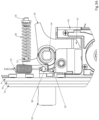
- the rest position is shown in figures 2A and 2B and the actuated position is shown in figure 2C .
- the spindle follower 24 comprises a protrusion 29 guided in a groove 30 provided in the upstanding edge 10 of the base plate 8.
- the latch bolt actuating mechanism further comprises the gear member 31.
- the gear member 31 comprises a first gear part 36 and the latch bolt lever 26 comprises a second gear part 35.
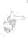
- These gear parts 35, 36 engage one another (as shown in figure 3A ) to transfer a rotation of the spindle follower 24 to the gear member 31.
- the gear parts 35, 36 on the spindle follower 24 and the gear member 31 form a bevel gear which transfers a pivoting motion of the spindle follower 24 about the rotation axis 25 to a rotation of the gear member 31 about the rotation axis 37. Since only a small angular rotation is required, it is clear that both the gear parts 35, 36 have to show only one or two mutually engaging notches or teeth.
- a rotation of the handles 21 about the pivot axis 25 causes the spindle follower 24 to be rotated from its rest position (shown in figures 2A and 2B ) to its actuated position (shown in figure 2C ) against the force of the compression spring 28.
- This rotation affects the gear member 31 which is rotated, against the force of the tension spring 32, form its idle state (shown in figures 2A and 2B ) to its activated state (shown in figure 2C ).
- the latch bolt 4, which is non-rotatable with respect to the gear member 31, is thereby rotated from its latching state (shown in figures 2A and 2B ) to its unlatching state (shown in figure 2C ).
- the head portion of the above described lock 1 is arranged to be inserted through a slot in a bolt keeper (not shown).
- the slot is this bolt keeper has a width such that the bolt 4 can be guided through this slot in its unlatching position and that in its latching position the wings 39 secure the bolt behind the slot in the bolt keeper.
- the shape of the bolt head 40 defines a screw-like curve around the rotation axis 37 of the latch bolt 4. Due to the screw-like shape of this curve the translational motion of the latch bolt 4 (caused by sliding the closure member closed) is converted into a rotational motion thereof, more particularly in a rotation from the latching position of the latch bolt to its unlatching position.
- the lock 1 further comprises a locking mechanism for locking the latch bolt 4 in its latching position.
- the locking mechanism includes a base frame 42 fixed to the base plate 8 by means of screws 46.
- a locking member 50 is slidably mounted on the base frame 42.
- an accolade-shaped leaf spring 51 is arranged between the locking member 50 and the upstanding edge 10 of the base plate 8 and having its free extremities fixed into slots 47 in the upstanding edge 10.
- a recess 48 is also provided in the base frame 42 to accommodate the leaf spring 51.
- the locking member 50 can slide on the base frame 42 between an upper position (shown in figures 2B and 2C ) and a lower position (shown in figure 2A ) and shows an upper notch 52 for maintaining the locking member 50 by means of the leaf spring 51 in its upper position and a lower notch 53 for maintaining this locking member 50 by means of the spring 51 in its lower position.
- the locking member 50 is thus bi-stable due to the presence of the leaf spring 51.
- the locking member 50 shows further a first engagement surface 54 for lifting it to its upper position by means of the rotary driving bit 18 of the cylinder 17 and a second engagement surface 55 for lowering it again by means of the rotary driving bit 18 to its lower position.
- the locking member 50 shows a retaining notch 56 arranged to enclose in the upper position (i.e. the locking position) of the locking member 50 a projecting part 57 of the latch bolt lever 26 to prevent any rotation thereof and to release this projecting part 57 in the lower position (i.e. the unlocking position) of the locking member 50.
- the locking mechanism further includes a locking element 60 for locking the gear member 31.
- the locking element 60 is fixedly mounted on the locking member 50 and is thus slidable between an upper position (shown in figures 2B and 2C ) and a lower position (shown in figure 2A ).
- the locking element 60 is thus also bi-stable due to the presence of the leaf spring 51.
- the locking element 60 could be a separate element (i.e. not fixed to the locking member 50) that is slidable with respect to the base plate 8 between an upper and a lower position or more general between a locking state and an unlocking state.
- the locking element 60 has a distal end fixed to the locking member 50 and a free proximal end in which an opening 61 is provided.
- a flange 63 is provided in this opening 61 so as to position a compression spring 62 between the free proximal end of the locking element and the base plate 8.
- the proximal free end contacts a projecting part 65 of the gear member 31 to prevent a rotation of the gear member 31 caused by a person of ill intent attempting to forcibly rotate the latch bolt 4.
- the gear member 31 In the lower position (i.e. the unlocking position) of the locking element 60, the gear member 31 is free to rotate about the rotation axis 37.
- the compression spring 62 allows, when the locking element 60 is in its locking state, that the gear member 31 can displace the free proximal end of the locking element 60 against this compression spring 62 when the closure member is slid closed. In other words, a rotation of the latch bolt 4 from its latching state to its unlatching state caused by sliding closing motion of the closure member is allowed. The self-latching behavior of the lock 1 is thus maintained by this compression spring 62.
- the compression spring 62 is compressed thus always urging the locking element 60 away from the base frame 42.
- the compression spring 62 may then give rise to a torque of about 0,5 Nm which leads to a torque of about 35 Nm to be applied to the shaft part 38 to rotate the latch bolt 4 against the compression spring 62.
- this torque may rise to about 1,5 Nm corresponding to torque of about 110 Nm to be applied to the shaft part 38 to rotate the latch bolt 4 against the compression spring 62.
- other values may be used depending on the specific lock design.
- the head portion 40 of the latch bolt 4 engages one of the beveled longitudinal edges of a slot in the bolt keeper.
- the side surfaces of the lock wings 39 engage the edge of the slot along the screw-like curve and cause the latch bolt 4, and therefore also the gear member 31, to rotate against the force of the tension spring 32.
- the force of the compression spring 62 is also overcome.
- the tension spring 32 urges the gear member 31 and the latch bolt 4 again to their rest position wherein the latch bolt is in its latching position. In this position, the locking member 50 can be lifted by means of the key operated cylinder 17 to prevent any rotation of the door handles 21 and the gear member 31 in order to lock the closure member.
- the locking member 50 has first to be lowered again by rotating the key in the opposite direction. Subsequently, one of the handle can be actuated to rotate the spindle follower 24 and at the same time the gear member 31. The rotation of the gear member 31 causes a corresponding rotation of the latch bolt itself from its latching to its unlatching position. In this way, by pulling on the handle, the sliding closure member can be opened.
Landscapes
- Lock And Its Accessories (AREA)
Priority Applications (1)
| Application Number | Priority Date | Filing Date | Title |
|---|---|---|---|
| EP23218254.3A EP4575153A1 (de) | 2023-12-19 | 2023-12-19 | Verriegelung für ein schiebeverschlusselement und verschlusssystem damit |
Applications Claiming Priority (1)
| Application Number | Priority Date | Filing Date | Title |
|---|---|---|---|
| EP23218254.3A EP4575153A1 (de) | 2023-12-19 | 2023-12-19 | Verriegelung für ein schiebeverschlusselement und verschlusssystem damit |
Publications (1)
| Publication Number | Publication Date |
|---|---|
| EP4575153A1 true EP4575153A1 (de) | 2025-06-25 |
Family
ID=89224114
Family Applications (1)
| Application Number | Title | Priority Date | Filing Date |
|---|---|---|---|
| EP23218254.3A Pending EP4575153A1 (de) | 2023-12-19 | 2023-12-19 | Verriegelung für ein schiebeverschlusselement und verschlusssystem damit |
Country Status (1)
| Country | Link |
|---|---|
| EP (1) | EP4575153A1 (de) |
Citations (1)
| Publication number | Priority date | Publication date | Assignee | Title |
|---|---|---|---|---|
| EP1336708A1 (de) | 2002-02-11 | 2003-08-20 | Joseph Talpe, Jr. | Verschluss für Schiebetür oder -tor |
-
2023
- 2023-12-19 EP EP23218254.3A patent/EP4575153A1/de active Pending
Patent Citations (1)
| Publication number | Priority date | Publication date | Assignee | Title |
|---|---|---|---|---|
| EP1336708A1 (de) | 2002-02-11 | 2003-08-20 | Joseph Talpe, Jr. | Verschluss für Schiebetür oder -tor |
Similar Documents
| Publication | Publication Date | Title |
|---|---|---|
| CA3052497C (en) | Automatically-extendible deadbolt latch assembly | |
| EP1335085A1 (de) | Verschluss für Schiebetür oder -tor | |
| CN100354496C (zh) | 门用锁扣装置 | |
| RU2324042C2 (ru) | Блокирующий механизм для двери | |
| EP1334251A2 (de) | Mehrpunktschlosssystem | |
| CN113167081A (zh) | 锁组件 | |
| US5484179A (en) | Failsafe electric locking lever trim | |
| NZ270231A (en) | Door handle and latch mechanism with over-ride spring connected between slider and lift arm, and other modifications | |
| US20240360712A1 (en) | Hinge locking mechanism | |
| CN102770613A (zh) | 用于插芯锁组件的盖体 | |
| GB2226359A (en) | Improvements in or relating to lockable handle assemblies | |
| AU785407B2 (en) | Improvements in locks | |
| GB2226358A (en) | Improvements in or relating to handle assemblies | |
| WO2005108719A1 (en) | Security mechanism | |
| EP4596814A1 (de) | Kombinationsschloss zum verriegeln eines verschlusselements | |
| NZ781656A (en) | Carbon Offset Travel Transactions | |
| EP3252252B1 (de) | Schloss mit bolzen und falle | |
| NZ509090A (en) | Hook of sliding door lock slides and pivots within hollow carriage bolt | |
| GB2160251A (en) | Lockable door fastener | |
| AU2007201075A1 (en) | Improvements in Locks | |
| AU2021257926A1 (en) | A latchbolt assembly for mounting to a door | |
| AU2021221630A1 (en) | Lock with securable retainer for sliding panels and installation method | |
| HK1219766A1 (zh) | 能在防锁定状态下操作的短门边距榫眼锁组件 | |
| HK1219766B (en) | A short backset mortice lock assembly operable in an anti lockout condition | |
| AU1529500A (en) | Improvements in locks |
Legal Events
| Date | Code | Title | Description |
|---|---|---|---|
| PUAI | Public reference made under article 153(3) epc to a published international application that has entered the european phase |
Free format text: ORIGINAL CODE: 0009012 |
|
| STAA | Information on the status of an ep patent application or granted ep patent |
Free format text: STATUS: THE APPLICATION HAS BEEN PUBLISHED |
|
| AK | Designated contracting states |
Kind code of ref document: A1 Designated state(s): AL AT BE BG CH CY CZ DE DK EE ES FI FR GB GR HR HU IE IS IT LI LT LU LV MC ME MK MT NL NO PL PT RO RS SE SI SK SM TR |
|
| STAA | Information on the status of an ep patent application or granted ep patent |
Free format text: STATUS: REQUEST FOR EXAMINATION WAS MADE |
|
| 17P | Request for examination filed |
Effective date: 20251205 |