EP4575154A1 - Toleranzrückgewinnungssystem zur fixierung - Google Patents
Toleranzrückgewinnungssystem zur fixierung Download PDFInfo
- Publication number
- EP4575154A1 EP4575154A1 EP23220114.5A EP23220114A EP4575154A1 EP 4575154 A1 EP4575154 A1 EP 4575154A1 EP 23220114 A EP23220114 A EP 23220114A EP 4575154 A1 EP4575154 A1 EP 4575154A1
- Authority
- EP
- European Patent Office
- Prior art keywords
- compressible
- handle
- assembly
- door
- subassembly
- Prior art date
- Legal status (The legal status is an assumption and is not a legal conclusion. Google has not performed a legal analysis and makes no representation as to the accuracy of the status listed.)
- Pending
Links
Images


Classifications
-
- E—FIXED CONSTRUCTIONS
- E05—LOCKS; KEYS; WINDOW OR DOOR FITTINGS; SAFES
- E05B—LOCKS; ACCESSORIES THEREFOR; HANDCUFFS
- E05B85/00—Details of vehicle locks not provided for in groups E05B77/00 - E05B83/00
- E05B85/10—Handles
-
- E—FIXED CONSTRUCTIONS
- E05—LOCKS; KEYS; WINDOW OR DOOR FITTINGS; SAFES
- E05B—LOCKS; ACCESSORIES THEREFOR; HANDCUFFS
- E05B79/00—Mounting or connecting vehicle locks or parts thereof
- E05B79/02—Mounting of vehicle locks or parts thereof
- E05B79/06—Mounting of handles, e.g. to the wing or to the lock
-
- E—FIXED CONSTRUCTIONS
- E05—LOCKS; KEYS; WINDOW OR DOOR FITTINGS; SAFES
- E05B—LOCKS; ACCESSORIES THEREFOR; HANDCUFFS
- E05B15/00—Other details of locks; Parts for engagement by bolts of fastening devices
- E05B15/16—Use of special materials for parts of locks
- E05B15/1635—Use of special materials for parts of locks of plastics materials
- E05B2015/1678—Use of special materials for parts of locks of plastics materials for handle bearings
Definitions
- the present invention relates to a door handle intended to be mounted on a door of a motor vehicle, to an assembly of this door handle with a door panel and to a method for assembling the door panel and the door handle.
- misalignments can occur between different components when they are assembled during vehicle manufacturing. For example, when assembling a door handle with a corresponding door panel, misalignment can occur between the handle and the door panel.
- Misalignments between components can lead to a number of problems including reduced performance: for example misalignment between a door handle and a door panel can make the handle difficult to operate or create some aesthetical issues.
- the aim of the present invention is to solve at least part of the above-mentioned drawbacks.
- the invention is intended to provide a vehicle door handle, an assembly of this handle with a vehicle door panel and an assembly method, which are economical and simple to implement during automobile manufacturing.
- the invention relates to a door handle intended to be mounted on a door of a motor vehicle, comprising:
- the structure of the described door handle is adapted to receive at least part of the screwing assembly in order to be easily and conveniently assembled with a door panel during the manufacturing process.
- the door handle can also have one or more of the following features, taken alone or in combination.
- the compressible part has a hole adapted to receive at least part of the screwing assembly so as to allow to assemble together the handle part and a door panel.
- the hole facilitates the insertion of the screwing assembly into the compressible part.
- the handle part has a through-hole, and the compressible part extends along an axis of the through-hole, at least partially in the through-hole, and the compressible part extends, for example radially, from said axis towards the handle part.
- the compressible part is configured to deform when in contact with the screwing assembly.
- the compressible part may advantageously deform and exert an elastic force on the part of the screwing assembly that is inserted in the compressible part so as to adjust the insertion path of the screwing assembly into the compressible part and therefore mitigate any misalignment between the handle and the door panel.
- the compressible part is configured to deform in at least one of the following directions, for example in any of the following direction: a direction orthogonal to an axis of the through-hole and a direction along an axis of the through-hole.
- compression of the compressible part in the direction orthogonal to an axis of the through-hole may be restricted or prevented by the screwing assembly, and hence the screwing assembly may exert a force on the compressible part in the direction orthogonal to the axis of the through-hole.
- the metal part and the compressible part are arranged such that the metal part extends further than the compressible part along an axis of the through-hole, for example so as to allow the compressible part to deform along the same axis upon reception of the screwing assembly.
- the compressible part and the metal part are ring-shaped.
- a ring-shaped part has a good weight distribution, which means that it is less likely to cause vibration or noise. It is also easy to manufacture.
- the handle part comprises a first portion configured to rest on a door panel, for example on an outer side of a door panel, and a second portion having the through-hole and extending from the first portion, for example in a direction orthogonal to an axis of the through-hole.
- the described shape of the door handle allows it to be easily assembled with a door panel.
- the compressible part comprises an elastomer, in particular foam or rubber.
- Elastomeric materials are generally very durable and resistant to wear and tear.
- the subassembly can also have one or more of the following features, taken alone or in combination.
- the tip may be a conical shaped tip.
- the screwing assembly comprises a washer configured to be positioned on the screw between a head of the screw and around a shaft of the screw.
- the washer helps in distributing the load or force applied by the screw on the section so as to prevent the screw from damaging the handle part.
- the invention also relates to an assembly of a door panel and a subassembly according to what has been previously described, the assembly comprising:
- the assembly allows mitigating any misalignment due to manufacturing component tolerances.
- the invention also relates to a method for assembling a door panel and the subassembly according to what has been previously described, or the assembly previously described, comprising the following steps:
- the method uses a single screwing operation so it is simple and convenient to implement during a vehicle manufacturing.
- the method helps mitigating any misalignment due to manufacturing component tolerances.
- the invention relates to a door handle 10 intended to be mounted on a door of a motor vehicle, the motor vehicle being for example a car.
- the door is for example a car door.
- the door handle may be located nearby or on the B-pillar area or C-pillar area and/or in continuity of the window sealing.
- the door handle may be located near or on the B-pillar or C-pillar area and/or for example in continuity of the window sealing. Such positioning may facilitate easy and ergonomic access for the vehicle occupants.
- the door handle is located closer to the certain pillar than to another, for example closer to the B-pillar than to the C-pillar or the opposite, for example closer to the certain pillar than to any of the remaining pillars, for example among the remaining pillars among the A-pillar, the B-pillar, the C-pillar or the D-pillar, for example on one side of the car, or that the door handle is located closer the certain pillar than to any other equivalent structural element of the car.
- the door handle is located between the B-pillar and the C-pillar, or the B-pillar is located between the door handle and the C-pillar, for example in continuity of the window sealing.
- the window sealing is for example the window sealing of the door, or a window sealing common to the door and to another door of the motor vehicle.
- the door handle 10 may be positioned on the same side as the B-pillar or C-pillar C of the car.
- the handle may be located in close proximity to either B-pillar or C-pillar and/or in continuity of the window sealing, thereby facilitating easy and ergonomic access for the vehicle occupants.
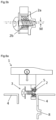
- the door handle 10 is presented in figure 1 .
- the door handle 10 comprises:
- the structure of the described door handle is adapted to receive at least part of the screwing assembly in order to be easily and conveniently assembled with a door panel during the manufacturing process.
- the handle part 1 may have a through-hole 7 that allows the handle part 1 to be easily assembled with the door panel 4.
- the handle part 1 may comprise one or more organic polymers, for example polycarbonate, ABS, polypropylene, polyamide glass fiber charged or other thermoplastics. This allows the handle part 1 to be lightweight, durable, and resistant to water and chemicals.
- the handle part may be made of one or more organic polymers.
- the handle part 1 may comprise a first portion 1a configured to rest on the door panel 4, for example on an outer side of a door panel 4.
- outer side of a door panel it is meant the exterior surface of a car door panel, the part of the door that is visible from the outside of the car.
- the first portion 1a may have a T-shape.
- the T-shape allows the first portion 1a to slide inside a space of the car all while resting on a door panel 4.
- the first portion 1a may comprise a first part 1a1 and a second part 1a2 which extends from the first part 1a1 towards the second portion 1b.
- the first part 1a1 may be a cross arm of the first portion 1a and the second part 1a2 may be the shaft that extends from the cross arm. This shape for the first portion 1a allows the first portion 1a to be easily assembled with a door panel.
- the first portion 1a may have a chamfer on at least one edge.
- the radius of curvature of the chamfer may be greater than or equal to 2.5 mm. This reduces the risk of injury for a user that may touch the handle part 1.
- the handle part 1 may also comprise a second portion 1b that extends from the first portion 1a, for example in a direction orthogonal to an axis X of the through-hole 7.
- the second portion 1b may have a rectangular shape.
- the first portion 1a may be made in one piece with the second portion 1b.
- the first portion 1a and the second portion 1b may be a single part molded in one piece.
- the second portion 1b may be overmolded onto the first portion 1a, for example according to a two-step process, for example after the molding of the first portion 1a.
- the first portion 1a may be overmolded onto the second portion 1b, for example according to a two-step process, for example after the molding of the second portion 1b.
- the second portion 1b may have the through-hole 7.
- the second portion 1b may for example have a shape chosen among one of the following: a cuboid, a rectangular prim, a parallelepiped. However, the second portion 1b may have any other shape. In the embodiment shown in figures 1 to 6c , the second portion 1b has a parallelepiped shaped.
- Figure 1 shows the compressible part 2 extending along an axis X of the through-hole 7.
- the entirety of the compressible part 2 extends in the through-hole 7.
- the dimension of the compressible part 2 according to an axis X of the through hole 7 is lesser than the dimension of the through-hole 7 along the same axis X.
- the compressible part 2 may extend radially with respect to said axis X, towards the handle part 1, for example towards the second portion 1b.
- the compressible part 2 may be configured to receive a screwing assembly 3.
- at least part of the screwing assembly 3 can be pressed into the compressible part 2 so as to penetrate and pass through the compressible part 2.
- screwing assembly it is for example meant an assembly comprising a screw, otherwise called screwing mechanism.
- the screwing assembly 3 can be pressed into the compressible part 2 so as to penetrate and pass through the compressible part 2, it is for example meant that the screwing assembly 3 can break through the compressible part 2 if the compressible part 2 does not have a hole in it.
- the compressible part 2 may have a hole 6 adapted to receive at least part of the screwing assembly 3 so as to allow to assemble together the handle part 1 and a door panel 4.
- the hole may have a circular shape 6 and/or may have a diameter comprised between M1 and M10, preferably M5.
- the hole 6 facilitates the insertion of the screwing assembly 3 into the compressible part 2.
- the compressible part 2 may comprise an elastomer, in particular foam or rubber. Elastomers are generally very durable and resistant to wear and tear.
- the compressible part 2 may comprise an elastomer, for example TPE, TPV, EPDM.
- the compressible part 2 may deform and/or compress while keeping a constant volume.
- the compressible part 2 When in a rest state, in other words, when the compressible part 2 is not in contact with the screwing assembly 3 and no other part is pressing on it, the compressible part 2 has an elongated ring shape, for example a cylindrical shape or an elliptical shape such as the one shown in figure 4b .
- the shape of the compressible part 2 may change and the compressible part 2 may deform and exert an elastic force on the part of the screwing assembly 3 that is inserted in the compressible part 2.
- the screwing assembly 3 is inserted at least partially in the compressible part 2.
- the screwing assembly 3 is screwed at least partially in the compressible part 2.
- the metal part 5 is presented in figures 1 to 6 .
- the metal part 5 may also have an elongated ring shape, for example for example a cylindrical shape or an elliptical shape and it may comprise a metal chosen from the list comprising the following metals: steel, aluminum.
- the metal part 5 may be made of one of the metals chosen from the list comprising the following metals: steel, aluminum, brass.
- the metal part 5 that is extending at least partially around the compressible part 2 is the same metal part 5 that is extending at least partially between the handle part 1 and the compressible part 2.
- the metal part 5 and the compressible part 2 may be arranged such that the metal part 5 extends further than the compressible part 2 along an axis X of the through-hole 7 as can be seen in figure 1 for instance.
- the handle part 1 and the metal part 5 are fixedly connected so that no movement occurs between them.
- the metal part 5 may be inserted forcefully in the handle part 1 or overmolded in the handle part 1 or inserted using hot insertion in the handle part 1.
- the compressible part 2 is fixedly connected to the metal part 5 so that the compressible part 2 is unable to slide along the central axis X with respect to the metal part 5.
- the compressible part 2 may extend only partially over the metal part.
- the compressible part may be of lesser length than the metal part 5.
- the dimension of the metal part 5 along axis X may be equal or greater than the dimension of the second portion 1b along axis X, and the dimension of compressible part 2 along axis X may be less than or equal to the dimension of the metal part 5 along axis X. These dimensions guarantee metal to metal contact.
- the second portion 1b may extend equally from both sides of the through-hole 7 with respect to axis Z and with respect to axis Y as can be seen in figure 4b .
- the described structure of the door handle 10 is adapted to receive at least part of the screwing assembly 3 in order to be easily and conveniently assembled with the door panel 4 during the manufacturing process.
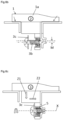
- the invention further relates to a subassembly 100 of a door handle 10 and a screwing assembly 3.
- the subassembly is presented in figure 2 .
- the subassembly comprises the door handle 10 and the screwing assembly 3.
- the screwing assembly 3 may comprise a screw configured to be inserted at least partially in the compressible part 2.
- the screw has a head 3a and a shaft 3b connected to the head 3a.
- the shaft 3b may be threaded.
- a threaded shaft provides a more secure and reliable means of connecting together then door handle 10 and the screwing assembly 3.
- the hole 6 may be threaded as well. Otherwise, the hole 6 may be a non-threaded hole.
- the shaft may have a tip 3d and the tip 3d may be a sharp one.
- a sharp tip it is meant that the distal end of the shaft 3b with respect to the head 3a is sharper than the proximal end of the shaft 3b with respect to the head 3a, and that it is configured to pierce the compressible part 2.
- the tip 3d may be a conical shaped tip.
- the screwing assembly 3 may be inserted at least partially in the compressible part 2 as presented in figure 2 .
- only part of the shaft 3b may be inserted in the compressible part 2 as presented in figure 2 .
- the invention further relates to an assembly 1000 of the subassembly 100 and the door panel 4.
- the door panel 4 may be a motor vehicle door panel, more specifically a car door panel.
- the assembly 1000 presented in figure 3 , comprises the subassembly 100 and the door panel 4.
- the door panel 4 has an aperture 8 adapted to receive at least part of the screwing assembly 3, so as to assemble together the subassembly 100 and the door panel 4.
- FIG 4a shows the screwing assembly 3 fully tightened and the handle part 10 assembled together with the door panel 4.
- the washer 3c is in direct contact with the metal part 5. This prevents the screw from sinking into the metal part 5 and damaging it and prevents the screwing assembly 3 from loosening.
- the assembly 1000 allows mitigating any misalignment between the aperture 8 and the screwing assembly 3 that is due to manufacturing component tolerances.
- the misalignment may include a tilt of the screwing assembly 3 with respect to the insertion path of the shaft 3b.
- Figure 5a first shows an example where the screwing assembly 3 is only partially inserted in the compressible part 2 and where misalignment M occurs between the subassembly 100 and the aperture 8.
- axis X that passes through the through-hole 7, in the center of the through-hole 7, and an axis G that passes through the aperture 8, in the center of aperture 8, do not coincide.
- the compressible part 2 deforms on contact with the shaft 3b when the shaft 3b is guided by aperture 8 to adjust the trajectory of the screwing assembly 3 as it is tightened to assemble together the handle part 1 and the door panel 4.
- the screwing assembly 3 causes the compressible part to compress in order to correct the misalignment M and to allow to assemble together the handle part 1 and the door panel 4.
- Figure 5b also shows the assembly 1000 when the screw has been fully tightened and the washer 3c is in contact with the metal part 5.
- the lower part 2b of the compressible part 2 has a width less than the upper part 2a. This is due to the fact that the lower part 2b is being compressed by the shaft 3b so that the misalignment M is reduced so that the shaft 3b is able to pass, at least partially, through both the compressible part 2 and the aperture 8 in order to assemble together the handle part 1 and the door panel 4.
- Steps of the method are presented in figure 6a , 6b, 6c .
- the method first comprises a step of providing the subassembly 100 as presented in figure 6a .
- the subassembly is provided with the screwing assembly 3 inserted partially in the compressible part 2 so that the subassembly 100 is able to slide in the space between the two distinct parts of the door panel 4 as can be seen in figure 6b .
- the subassembly is pushed towards the door panel 4 so that the first portion 1a is in contact with the door panel 4.
- the first portion 1a rests on the two distinct parts of the door panel 4 as shown in figure 6b .
- the method comprises a step of positioning the subassembly 100 so as to have the compressible part 2 facing the aperture 8 of the door panel 4.
- the second portion 1b is entirely inside the space between the two distinct parts of the door panel 4, and the compressible part 2 is positioned so as to face the aperture 8 of the door panel 4.
- the compressible part 2 is positioned so that the shaft 3b is able to, at least partially; pass through both the compressible part 2 and the aperture 8. Because of components manufacturing tolerances, the misalignment M can occur in this step.
- the method further comprises a step of tightening the screwing assembly 3 until at least part of the screwing assembly 3 is in contact with the metal part 5, and until at least part of the screwing assembly 3 passes through both the compressible part 2 and the aperture 8 as can be seen in figure 6c .
- the screw is tightened, possibly with a screw driver, until the shaft 3b passes through both the compressible part 2 and the aperture 8 and the washer 3c (or the head of the screw 3a if no washer is present) is in contact with the metal part 5.
- the tightening of the screw results in the door handle 10 being pushed both in a first direction Z1 orthogonal to an axis X of the through-hole 7 towards the inner side of the door panel 4, and in a second direction Z2 towards the part of the door handle 4 that has the aperture 8.
- the compressible part 2 When the screwing assembly 3 is in contact with the compressible part 2, the compressible part 2 deforms and is able to change its shape in order to adjust the insertion path of the shaft 3b in the compressible part 2. This helps in reducing any misalignment that might occur between the screwing assembly 3 and the aperture 8. In other words, the compressible part 2 may exert an elastic force on the screwing assembly 3 so as to secure the subassembly 100 and the door panel 4 together.
Landscapes
- Lock And Its Accessories (AREA)
- Connection Of Plates (AREA)
Priority Applications (4)
| Application Number | Priority Date | Filing Date | Title |
|---|---|---|---|
| EP23220114.5A EP4575154A1 (de) | 2023-12-22 | 2023-12-22 | Toleranzrückgewinnungssystem zur fixierung |
| US18/983,828 US20250207438A1 (en) | 2023-12-22 | 2024-12-17 | Door handle and assembly method to mitigate component tolerances |
| CN202411880689.1A CN120193716A (zh) | 2023-12-22 | 2024-12-19 | 减轻部件公差的门把手和组装方法 |
| JP2024224663A JP2025106215A (ja) | 2023-12-22 | 2024-12-20 | 部品間の許容誤差を軽減するドアハンドル及びその組み立て方法 |
Applications Claiming Priority (1)
| Application Number | Priority Date | Filing Date | Title |
|---|---|---|---|
| EP23220114.5A EP4575154A1 (de) | 2023-12-22 | 2023-12-22 | Toleranzrückgewinnungssystem zur fixierung |
Publications (1)
| Publication Number | Publication Date |
|---|---|
| EP4575154A1 true EP4575154A1 (de) | 2025-06-25 |
Family
ID=89321559
Family Applications (1)
| Application Number | Title | Priority Date | Filing Date |
|---|---|---|---|
| EP23220114.5A Pending EP4575154A1 (de) | 2023-12-22 | 2023-12-22 | Toleranzrückgewinnungssystem zur fixierung |
Country Status (4)
| Country | Link |
|---|---|
| US (1) | US20250207438A1 (de) |
| EP (1) | EP4575154A1 (de) |
| JP (1) | JP2025106215A (de) |
| CN (1) | CN120193716A (de) |
Citations (4)
| Publication number | Priority date | Publication date | Assignee | Title |
|---|---|---|---|---|
| EP1929161A1 (de) | 2005-09-26 | 2008-06-11 | Acument GmbH & Co. OHG | Spezialmutter und verbindung |
| FR3088085A1 (fr) * | 2018-11-07 | 2020-05-08 | Psa Automobiles Sa | Commande d’ouverture exterieure d’ouvrant avec moyen de centrage et moyen de premaintien combines et vehicule comprenant une telle commande |
| CN218668929U (zh) * | 2022-10-28 | 2023-03-21 | 上海霍富汽车锁具有限公司 | 带有可平衡调节公差吸收器的汽车隐形把手 |
| CN219241621U (zh) * | 2023-02-17 | 2023-06-23 | 重庆长安汽车股份有限公司 | 一种公差调节器及手柄总成 |
-
2023
- 2023-12-22 EP EP23220114.5A patent/EP4575154A1/de active Pending
-
2024
- 2024-12-17 US US18/983,828 patent/US20250207438A1/en active Pending
- 2024-12-19 CN CN202411880689.1A patent/CN120193716A/zh active Pending
- 2024-12-20 JP JP2024224663A patent/JP2025106215A/ja active Pending
Patent Citations (4)
| Publication number | Priority date | Publication date | Assignee | Title |
|---|---|---|---|---|
| EP1929161A1 (de) | 2005-09-26 | 2008-06-11 | Acument GmbH & Co. OHG | Spezialmutter und verbindung |
| FR3088085A1 (fr) * | 2018-11-07 | 2020-05-08 | Psa Automobiles Sa | Commande d’ouverture exterieure d’ouvrant avec moyen de centrage et moyen de premaintien combines et vehicule comprenant une telle commande |
| CN218668929U (zh) * | 2022-10-28 | 2023-03-21 | 上海霍富汽车锁具有限公司 | 带有可平衡调节公差吸收器的汽车隐形把手 |
| CN219241621U (zh) * | 2023-02-17 | 2023-06-23 | 重庆长安汽车股份有限公司 | 一种公差调节器及手柄总成 |
Also Published As
| Publication number | Publication date |
|---|---|
| CN120193716A (zh) | 2025-06-24 |
| JP2025106215A (ja) | 2025-07-15 |
| US20250207438A1 (en) | 2025-06-26 |
Similar Documents
| Publication | Publication Date | Title |
|---|---|---|
| US10124744B2 (en) | Clip for fastening a panel on a support, method for implementing same, and motor vehicle equipment | |
| US7096638B2 (en) | Low insertion effort U-base retainer | |
| US10322750B2 (en) | Power steering assembly mounts with tapered protrusions | |
| CN111911588B (zh) | 紧固组件的间距保持件、紧固组件和紧固方法 | |
| US8017870B2 (en) | Fastening device for a line | |
| EP2835541B1 (de) | Nicht klappernde Hülse für eine Gelenkverbindung | |
| US20030205014A1 (en) | Arrangement for attaching an assembly component with variable spacing to an understructure | |
| JP5498890B2 (ja) | 自動車用の閉塞栓 | |
| US11654764B2 (en) | Vibration-damping device body and vibration-damping device | |
| JP2014527140A (ja) | 互いに固定された少なくとも2つの構成部品を備える組立体 | |
| US20230278661A1 (en) | Drive assembly | |
| EP4575154A1 (de) | Toleranzrückgewinnungssystem zur fixierung | |
| CN111033079B (zh) | 索环 | |
| JP2018071768A (ja) | 防振装置 | |
| EP2980444A1 (de) | Drehmomentstange | |
| US7600803B2 (en) | Windshield wiper, especially for a motor vehicle | |
| KR20220149819A (ko) | 자동차용 대시 인슐레이션 마운팅 클립 | |
| EP2927510A1 (de) | Befestigungselement | |
| CN106467050B (zh) | 用于机动车辆的双成型拉手隔离件 | |
| KR100435273B1 (ko) | 자동차용 엔진 마운트 | |
| US20250389291A1 (en) | Fastener, Fastening Assembly and Vehicle | |
| CN114450493A (zh) | 具有压缩限制器肩部的铆钉螺母 | |
| EP4296531A1 (de) | Befestigungsstruktur zwischen kurbelwelle und torsionsdämpfer | |
| US20260084635A1 (en) | Grommet Apparatus | |
| US5803644A (en) | Reinforced fastening connection |
Legal Events
| Date | Code | Title | Description |
|---|---|---|---|
| PUAI | Public reference made under article 153(3) epc to a published international application that has entered the european phase |
Free format text: ORIGINAL CODE: 0009012 |
|
| STAA | Information on the status of an ep patent application or granted ep patent |
Free format text: STATUS: REQUEST FOR EXAMINATION WAS MADE |
|
| 17P | Request for examination filed |
Effective date: 20231222 |
|
| AK | Designated contracting states |
Kind code of ref document: A1 Designated state(s): AL AT BE BG CH CY CZ DE DK EE ES FI FR GB GR HR HU IE IS IT LI LT LU LV MC ME MK MT NL NO PL PT RO RS SE SI SK SM TR |