EP4575206A1 - Ensemble tuyère à section variable pour un système de propulsion d'aéronef - Google Patents
Ensemble tuyère à section variable pour un système de propulsion d'aéronef Download PDFInfo
- Publication number
- EP4575206A1 EP4575206A1 EP24222638.9A EP24222638A EP4575206A1 EP 4575206 A1 EP4575206 A1 EP 4575206A1 EP 24222638 A EP24222638 A EP 24222638A EP 4575206 A1 EP4575206 A1 EP 4575206A1
- Authority
- EP
- European Patent Office
- Prior art keywords
- nozzle
- protrusion
- disposed
- gap
- inner radial
- Prior art date
- Legal status (The legal status is an assumption and is not a legal conclusion. Google has not performed a legal analysis and makes no representation as to the accuracy of the status listed.)
- Pending
Links
Images



Classifications
-
- B—PERFORMING OPERATIONS; TRANSPORTING
- B64—AIRCRAFT; AVIATION; COSMONAUTICS
- B64D—EQUIPMENT FOR FITTING IN OR TO AIRCRAFT; FLIGHT SUITS; PARACHUTES; ARRANGEMENT OR MOUNTING OF POWER PLANTS OR PROPULSION TRANSMISSIONS IN AIRCRAFT
- B64D27/00—Arrangement or mounting of power plants in aircraft; Aircraft characterised by the type or position of power plants
- B64D27/02—Aircraft characterised by the type or position of power plants
- B64D27/10—Aircraft characterised by the type or position of power plants of gas-turbine type
-
- B—PERFORMING OPERATIONS; TRANSPORTING
- B64—AIRCRAFT; AVIATION; COSMONAUTICS
- B64D—EQUIPMENT FOR FITTING IN OR TO AIRCRAFT; FLIGHT SUITS; PARACHUTES; ARRANGEMENT OR MOUNTING OF POWER PLANTS OR PROPULSION TRANSMISSIONS IN AIRCRAFT
- B64D33/00—Arrangement in aircraft of power plant parts or auxiliaries not otherwise provided for
- B64D33/04—Arrangement in aircraft of power plant parts or auxiliaries not otherwise provided for of exhaust outlets or jet pipes
-
- F—MECHANICAL ENGINEERING; LIGHTING; HEATING; WEAPONS; BLASTING
- F01—MACHINES OR ENGINES IN GENERAL; ENGINE PLANTS IN GENERAL; STEAM ENGINES
- F01D—NON-POSITIVE DISPLACEMENT MACHINES OR ENGINES, e.g. STEAM TURBINES
- F01D17/00—Regulating or controlling by varying flow
- F01D17/10—Final actuators
- F01D17/12—Final actuators arranged in stator parts
- F01D17/14—Final actuators arranged in stator parts varying effective cross-sectional area of nozzles or guide conduits
-
- F—MECHANICAL ENGINEERING; LIGHTING; HEATING; WEAPONS; BLASTING
- F01—MACHINES OR ENGINES IN GENERAL; ENGINE PLANTS IN GENERAL; STEAM ENGINES
- F01D—NON-POSITIVE DISPLACEMENT MACHINES OR ENGINES, e.g. STEAM TURBINES
- F01D17/00—Regulating or controlling by varying flow
- F01D17/10—Final actuators
- F01D17/12—Final actuators arranged in stator parts
- F01D17/14—Final actuators arranged in stator parts varying effective cross-sectional area of nozzles or guide conduits
- F01D17/16—Final actuators arranged in stator parts varying effective cross-sectional area of nozzles or guide conduits by means of nozzle vanes
-
- F—MECHANICAL ENGINEERING; LIGHTING; HEATING; WEAPONS; BLASTING
- F02—COMBUSTION ENGINES; HOT-GAS OR COMBUSTION-PRODUCT ENGINE PLANTS
- F02C—GAS-TURBINE PLANTS; AIR INTAKES FOR JET-PROPULSION PLANTS; CONTROLLING FUEL SUPPLY IN AIR-BREATHING JET-PROPULSION PLANTS
- F02C7/00—Features, components parts, details or accessories, not provided for in, or of interest apart form groups F02C1/00 - F02C6/00; Air intakes for jet-propulsion plants
- F02C7/12—Cooling of plants
- F02C7/16—Cooling of plants characterised by cooling medium
- F02C7/18—Cooling of plants characterised by cooling medium the medium being gaseous, e.g. air
-
- F—MECHANICAL ENGINEERING; LIGHTING; HEATING; WEAPONS; BLASTING
- F02—COMBUSTION ENGINES; HOT-GAS OR COMBUSTION-PRODUCT ENGINE PLANTS
- F02K—JET-PROPULSION PLANTS
- F02K1/00—Plants characterised by the form or arrangement of the jet pipe or nozzle; Jet pipes or nozzles peculiar thereto
- F02K1/06—Varying effective area of jet pipe or nozzle
- F02K1/08—Varying effective area of jet pipe or nozzle by axially moving or transversely deforming an internal member, e.g. the exhaust cone
-
- F—MECHANICAL ENGINEERING; LIGHTING; HEATING; WEAPONS; BLASTING
- F02—COMBUSTION ENGINES; HOT-GAS OR COMBUSTION-PRODUCT ENGINE PLANTS
- F02K—JET-PROPULSION PLANTS
- F02K1/00—Plants characterised by the form or arrangement of the jet pipe or nozzle; Jet pipes or nozzles peculiar thereto
- F02K1/38—Introducing air inside the jet
- F02K1/383—Introducing air inside the jet with retractable elements
-
- F—MECHANICAL ENGINEERING; LIGHTING; HEATING; WEAPONS; BLASTING
- F05—INDEXING SCHEMES RELATING TO ENGINES OR PUMPS IN VARIOUS SUBCLASSES OF CLASSES F01-F04
- F05D—INDEXING SCHEME FOR ASPECTS RELATING TO NON-POSITIVE-DISPLACEMENT MACHINES OR ENGINES, GAS-TURBINES OR JET-PROPULSION PLANTS
- F05D2220/00—Application
- F05D2220/30—Application in turbines
- F05D2220/32—Application in turbines in gas turbines
- F05D2220/323—Application in turbines in gas turbines for aircraft propulsion, e.g. jet engines
-
- F—MECHANICAL ENGINEERING; LIGHTING; HEATING; WEAPONS; BLASTING
- F05—INDEXING SCHEMES RELATING TO ENGINES OR PUMPS IN VARIOUS SUBCLASSES OF CLASSES F01-F04
- F05D—INDEXING SCHEME FOR ASPECTS RELATING TO NON-POSITIVE-DISPLACEMENT MACHINES OR ENGINES, GAS-TURBINES OR JET-PROPULSION PLANTS
- F05D2250/00—Geometry
- F05D2250/90—Variable geometry
-
- F—MECHANICAL ENGINEERING; LIGHTING; HEATING; WEAPONS; BLASTING
- F05—INDEXING SCHEMES RELATING TO ENGINES OR PUMPS IN VARIOUS SUBCLASSES OF CLASSES F01-F04
- F05D—INDEXING SCHEME FOR ASPECTS RELATING TO NON-POSITIVE-DISPLACEMENT MACHINES OR ENGINES, GAS-TURBINES OR JET-PROPULSION PLANTS
- F05D2260/00—Function
- F05D2260/60—Fluid transfer
- F05D2260/605—Venting into the ambient atmosphere or the like
-
- F—MECHANICAL ENGINEERING; LIGHTING; HEATING; WEAPONS; BLASTING
- F05—INDEXING SCHEMES RELATING TO ENGINES OR PUMPS IN VARIOUS SUBCLASSES OF CLASSES F01-F04
- F05D—INDEXING SCHEME FOR ASPECTS RELATING TO NON-POSITIVE-DISPLACEMENT MACHINES OR ENGINES, GAS-TURBINES OR JET-PROPULSION PLANTS
- F05D2260/00—Function
- F05D2260/60—Fluid transfer
- F05D2260/608—Aeration, ventilation, dehumidification or moisture removal of closed spaces
Definitions
- the nacelle 24 is configured to house and provide an aerodynamic cover for the gas turbine engine 22.
- the nacelle 24 may circumscribe (e.g., extend circumferentially about) and form an annular bypass duct 72 through the propulsion system 20.
- the bypass duct 72 may be formed by and between (e.g., radially between) the gas turbine engine 22 and the nacelle 24.
- the bypass duct 72 may extend (e.g., axially extend) between and to the fan section 30 and the exhaust section 38.
- ambient air enters the gas turbine engine 22 and is directed through the engine sections 32, 34, 36, 38 along a core flow path 74.
- the air within the core flow path 74 may be referred to as "core air.”
- the core air is compressed in the low-pressure compressor 42 and the high-pressure compressor 44 by the bladed second compressor rotor 66 and the bladed first compressor rotor 60, respectively, and directed into a combustion chamber of the combustor 46. Fuel is injected into the combustion chamber and mixed with the compressed core air to provide a fuel-air mixture.
- all or substantially all of the bypass air may be directed along the inner bypass flow path 80 to a position radially inward of the core flow path 74.
- the exhaust section 38 may not form an outer bypass flow path such as the outer bypass flow path 78).
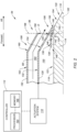
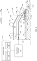
- FIGS. 2 and 3 illustrate a portion of an exhaust section 94 for an aircraft propulsion system such as the propulsion system 20 of FIG. 1 .
- the exhaust section 94 of FIGS. 2 and 3 includes an embodiment of a variable area nozzle assembly 96 configured to control gas (e.g., air, combustion exhaust, etc.) flow through the exhaust section 94.
- the variable area nozzle assembly 96 is configured to control the flow of a primary gas stream 98 and a secondary gas stream 100 through the exhaust section 94.
- the primary gas stream 98 may be an engine exhaust gas stream such as, but not limited to, the core combustion gas flow along the core flow path 74 of FIG. 1 .
- the secondary gas stream 100 may be an air stream (e.g., a bypass air stream, a compressed air stream, etc.) such as, but not limited to, the bypass air flow along the inner bypass flow path 80 of FIG. 1 .
- the primary gas stream 98 of FIGS. 2 and 3 is disposed radially outward (e.g., outboard) of the secondary gas stream 100 within the variable area nozzle assembly 96.
- the present invention is not limited to the foregoing exemplary gas streams illustrated in FIGS. 2 and 3 .
- the center plug 104 is disposed at (e.g., on, adjacent, or proximate) the axis 102 forming an axial center of the variable area nozzle assembly 96.
- the center plug 104 of FIGS. 2 and 3 is fixed relative to the axis 102.
- the center plug 104 includes a plug body 114.
- the plug body 114 extends along the axis 102 to a distal end 116 (e.g., an aft end) of the plug body 114.
- the plug body 114 includes an outer radial side 118.
- the outer radial side 118 extends about (e.g., circumferentially completely around) the axis 102.
- the outer radial side 118 may form a converging portion 120 and an upstream portion 122.
- the converging portion 120 may be disposed at (e.g., on, adjacent, or proximate) the distal end 116.
- the upstream portion 122 extends in an upstream direction (e.g., an axially forward direction) from the converging portion 120.
- the plug body 114 forms or otherwise includes a protrusion 124 at (e.g., on, adjacent, or proximate) the outer radial side 118.
- the protrusion 124 may be an annular protrusion of the plug body 114 extending circumferentially about (e.g., completely around) the axis 102.
- the protrusion 124 extends (e.g., radially extends) from the outer radial side 118 to a distal radial end 126.
- the protrusion 124 may alternatively be an annular seal or other annular body mounted to or otherwise disposed at (e.g., on, adjacent, or proximate) the outer radial side 118.
- the inner nozzle 106 is disposed radially outward of and adjacent the center plug 104.
- the inner nozzle 106 includes an inner nozzle body 128.
- the inner nozzle body 128 forms an annular secondary duct 130 between (e.g., radially between) the inner nozzle body 128 and the plug body 114.
- the secondary gas stream 100 flows (e.g., is directed) through the variable area nozzle assembly 96 within the secondary duct 130.
- the inner nozzle body 128 of FIGS. 2 and 3 includes an outer radial portion 132, a converging portion 134, and an inner radial portion 136.
- Each of the outer radial portion 132, the converging portion 134, and the inner radial portion 136 extend circumferentially about (e.g., completely around) the center plug 104 and the axis 102.
- the converging portion 134 extends between and to the outer radial portion 132 and the inner radial portion 136.
- the converging portion 134 extends radially inward and axially aftward from the outer radial portion 132 to the inner radial portion 136.
- the inner radial portion 136 is disposed radially inward of and spaced from the outer radial portion 132.
- the inner radial portion 136 extends (e.g., axially extends) from the converging portion 134 to a distal end 138 of the inner radial portion 136.
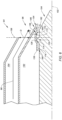
- the inner radial portion 136 of FIGS. 2 and 3 forms a first inner radial surface 140, a second inner radial surface 142, and an oblique surface 144.
- the first inner radial surface 140, the second inner radial surface 142, and the oblique surface 144 may face and extend circumferentially about (e.g., completely around) the center plug 104 and the axis 102.
- the first inner radial surface 140 may be disposed at (e.g., on, adjacent, or proximate) the converging portion 134.
- the first inner radial surface 140 may be disposed radially inward of the distal radial end 126.
- the first inner radial surface 140 may be disposed downstream (e.g., axially aft) of the protrusion 124.
- the oblique surface 144 may extend between and to the first inner radial surface 140 and the second inner radial surface 142.
- the oblique surface 144 may extend in a radially outward direction from the first inner radial surface 140 to the second inner radial surface 142.
- the second inner radial surface 142 may be disposed at (e.g., on, adjacent, or proximate) the distal end 138.
- the second inner radial surface 142 may extend (e.g., axially extend) between and to the oblique surface 144 and the distal end 138.
- the second inner radial surface 142 is disposed radially outward of the first inner radial surface 140.
- the second inner radial surface 142 may be disposed radially outward of the distal radial end 126.
- upstream and downstream may be understood relative to a flow direction of the primary gas stream 98 and/or the secondary gas stream 100.
- the first inner radial surface 140, the second inner radial surface 142, and the oblique surface 144 form a gap 146 (e.g., an annular gap) radially between the inner radial portion 136 and the plug body 114 (e.g., the outer radial side 118).
- the gap 146 forms a nozzle outlet of the variable area nozzle assembly 96 for the secondary duct 130.
- the gap 146 includes an inlet 148 and an outlet 150.
- the inlet 148 is disposed at (e.g., on, adjacent, or proximate) the distal end 138.
- the inlet 148 is disposed at (e.g., on, adjacent, or proximate) and in fluid communication with the secondary duct 130.
- the outlet 150 is disposed downstream of the protrusion 124.
- the inner nozzle 106 is axially translatable along the axis 102 between and to a retracted axial position (e.g., a forwardmost axial position) and an extended axial position (e.g., an aftmost axial position).
- FIG. 2 illustrates the inner nozzle 106 in the retracted axial position.
- FIG. 3 illustrates the inner nozzle 106 in the extended axial position.
- the inner nozzle 106 may be positionable in one or more intermediate axial positions between the retracted axial position and the extended axial position. In the retracted axial position of the inner nozzle 106 of FIGS.
- the protrusion 124 is disposed at (e.g., on, adjacent, or proximate) the inner radial portion 136.
- the protrusion 124 may be positioned to contact the inner radial portion 136 (e.g., the oblique surface 144).
- the inlet 148 may be isolated from the outlet 150 such that there is no or substantially no flow of the secondary gas stream 100 through the gap 146.
- the protrusion 124 may be separated from (e.g., axially and radially spaced from) the inner radial portion 136 (e.g., the oblique surface).
- the secondary gas stream 100 is directed from the secondary duct 130 into the inlet 148 and through the gap 146 to the outlet 150.
- the outer nozzle 108 is disposed radially outward of and adjacent the inner nozzle 106.
- the outer nozzle 108 includes an outer nozzle body 152.
- the outer nozzle body 152 forms an annular primary duct 154 between (e.g., radially between) the outer nozzle body 152 and the inner nozzle body 128.
- the primary gas stream 98 flows (e.g., is directed) through the variable area nozzle assembly 96 within the primary duct 154.
- the outer nozzle body 152 may be fixed relative to the axis 102.
- the outer nozzle body 152 extends along the axis 102 to a distal end 156 (e.g., an at end) of the outer nozzle body 152.
- the distal end 156 may be disposed upstream (e.g., axially forward) of the distal end 116.
- the outer nozzle body 152 forms an exit plane 158 of the variable area nozzle assembly 96 for the primary gas stream 98 at (e.g., on, adjacent, or proximate) the distal end 156.
- the outer nozzle body 152 includes a converging portion 160 and an upstream portion 162.
- the converging portion 160 is disposed at (e.g., on, adjacent, or proximate) the distal end 156.
- the converging portion 160 extends radially inward and axially aftward from the upstream portion 162 to the distal end 156.
- the converging portion 160 is disposed axially coincident with the converging portion 134.
- the converging portion 160 is spaced from the converging portion 134 by a distance D (e.g., a radial distance) along the exit plane 158 to form an annular exit cross-sectional area for the primary duct 154 at (e.g., on, adjacent, or proximate) the exit plane 158.
- the upstream portion 162 extends in an upstream direction (e.g., an axially forward direction) from the converging portion 160.
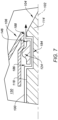
- the inlet 180 may be isolated from the outlet 182 such that there is no or substantially no flow of the secondary gas stream 100 through the gap 178.
- the protrusion 124 may be separated from (e.g., axially and radially spaced from) the inner radial portion 136 (e.g., the first oblique surface 170 and the second oblique surface 174).
- the secondary gas stream 100 is directed from the secondary duct 130 into the inlet 180 and through the gap 178 to the outlet 182.
- the terms “comprise”, “comprising”, or any other variation thereof, are intended to cover a non-exclusive inclusion, such that a process, method, article, or apparatus that comprises a list of elements does not include only those elements but may include other elements not expressly listed or inherent to such process, method, article, or apparatus.
Landscapes
- Engineering & Computer Science (AREA)
- Mechanical Engineering (AREA)
- General Engineering & Computer Science (AREA)
- Chemical & Material Sciences (AREA)
- Combustion & Propulsion (AREA)
- Aviation & Aerospace Engineering (AREA)
- Control Of Turbines (AREA)
Applications Claiming Priority (1)
| Application Number | Priority Date | Filing Date | Title |
|---|---|---|---|
| US18/394,669 US12065937B1 (en) | 2023-12-22 | 2023-12-22 | Variable area nozzle assembly for an aircraft propulsion system |
Publications (1)
| Publication Number | Publication Date |
|---|---|
| EP4575206A1 true EP4575206A1 (fr) | 2025-06-25 |
Family
ID=92305696
Family Applications (1)
| Application Number | Title | Priority Date | Filing Date |
|---|---|---|---|
| EP24222638.9A Pending EP4575206A1 (fr) | 2023-12-22 | 2024-12-20 | Ensemble tuyère à section variable pour un système de propulsion d'aéronef |
Country Status (2)
| Country | Link |
|---|---|
| US (1) | US12065937B1 (fr) |
| EP (1) | EP4575206A1 (fr) |
Citations (4)
| Publication number | Priority date | Publication date | Assignee | Title |
|---|---|---|---|---|
| US20050047942A1 (en) * | 2003-08-25 | 2005-03-03 | Grffin Rollin George | Flade gas turbine engine with counter-rotatable fans |
| US20070186535A1 (en) * | 2006-02-13 | 2007-08-16 | General Electric Company | Double bypass turbofan |
| US20150113941A1 (en) * | 2013-10-24 | 2015-04-30 | United Technologies Corporation | Translating outer cowl flow modulation device and method |
| US20200102913A1 (en) * | 2013-09-20 | 2020-04-02 | United Technologies Corporation | Auxiliary device for three air flow path gas turbine engine |
Family Cites Families (5)
| Publication number | Priority date | Publication date | Assignee | Title |
|---|---|---|---|---|
| US4072008A (en) * | 1976-05-04 | 1978-02-07 | General Electric Company | Variable area bypass injector system |
| GB2165892B (en) | 1984-10-22 | 1988-10-26 | Gen Electric | Variable cycle engine |
| US7681399B2 (en) * | 2006-11-14 | 2010-03-23 | General Electric Company | Turbofan engine cowl assembly and method of operating the same |
| US8739548B2 (en) * | 2007-12-20 | 2014-06-03 | United Technologies Corporation | Sliding ramp nozzle system for a gas turbine engine |
| US10371089B2 (en) * | 2015-01-20 | 2019-08-06 | United Technologies Corporation | System for actuating an exhaust cowl |
-
2023
- 2023-12-22 US US18/394,669 patent/US12065937B1/en active Active
-
2024
- 2024-12-20 EP EP24222638.9A patent/EP4575206A1/fr active Pending
Patent Citations (4)
| Publication number | Priority date | Publication date | Assignee | Title |
|---|---|---|---|---|
| US20050047942A1 (en) * | 2003-08-25 | 2005-03-03 | Grffin Rollin George | Flade gas turbine engine with counter-rotatable fans |
| US20070186535A1 (en) * | 2006-02-13 | 2007-08-16 | General Electric Company | Double bypass turbofan |
| US20200102913A1 (en) * | 2013-09-20 | 2020-04-02 | United Technologies Corporation | Auxiliary device for three air flow path gas turbine engine |
| US20150113941A1 (en) * | 2013-10-24 | 2015-04-30 | United Technologies Corporation | Translating outer cowl flow modulation device and method |
Also Published As
| Publication number | Publication date |
|---|---|
| US12065937B1 (en) | 2024-08-20 |
Similar Documents
| Publication | Publication Date | Title |
|---|---|---|
| EP1939437B1 (fr) | Moteur de turbine doté d'un ventilateur à débit modulé et son procédé de fonctionnement | |
| US20170145956A1 (en) | Thrust reverse feature control | |
| EP4575214A1 (fr) | Ensemble tuyère à section variable pour un système de propulsion d'aéronef | |
| US11661895B2 (en) | Autonomous safety mode for distributed control of turbomachines | |
| EP4575206A1 (fr) | Ensemble tuyère à section variable pour un système de propulsion d'aéronef | |
| EP4471267A1 (fr) | Turbomachine avec un système d'inversion de poussée | |
| US12292006B2 (en) | Aircraft propulsion system with multi-direction bleed valve | |
| EP4108897B1 (fr) | Système de propulsion d'aéronef doté d'une entrée à surface variable | |
| US11732673B2 (en) | Variable area exhaust nozzle system and method for control thereof | |
| US12454926B1 (en) | Exhaust nozzle assembly for an aircraft propulsion system | |
| US11859545B1 (en) | Aircraft propulsion system with variable area | |
| US20260062134A1 (en) | Assembly for identifying obstructing foreign matter in an air intake of an aircraft propulsion system and method of using same | |
| US20260117713A1 (en) | Systems and methods for operating an aircraft engine using multiple fuel types | |
| US20260117712A1 (en) | Systems and methods for operating an aircraft engine using multiple fuel types | |
| US20260117710A1 (en) | Systems and methods for operating an aircraft engine using multiple fuel types | |
| US20260117714A1 (en) | Systems and methods for operating an aircraft engine using multiple fuel types | |
| US20260117979A1 (en) | Systems and methods for operating an aircraft engine using multiple fuel types | |
| US20260117704A1 (en) | Systems and methods for operating an aircraft engine using multiple fuel types | |
| US12103695B2 (en) | Exhaust nozzle assembly for an aircraft propulsion system | |
| EP4368814A1 (fr) | Systèmes et procédés de commande de positions de jambe de force pour un ensemble jambe de force de système de propulsion d'aéronef | |
| US12312997B2 (en) | Turbine engine having a bleed system | |
| US12276229B2 (en) | Method of operating a turbine engine having a bleed system |
Legal Events
| Date | Code | Title | Description |
|---|---|---|---|
| PUAI | Public reference made under article 153(3) epc to a published international application that has entered the european phase |
Free format text: ORIGINAL CODE: 0009012 |
|
| STAA | Information on the status of an ep patent application or granted ep patent |
Free format text: STATUS: THE APPLICATION HAS BEEN PUBLISHED |
|
| AK | Designated contracting states |
Kind code of ref document: A1 Designated state(s): AL AT BE BG CH CY CZ DE DK EE ES FI FR GB GR HR HU IE IS IT LI LT LU LV MC ME MK MT NL NO PL PT RO RS SE SI SK SM TR |
|
| STAA | Information on the status of an ep patent application or granted ep patent |
Free format text: STATUS: REQUEST FOR EXAMINATION WAS MADE |
|
| 17P | Request for examination filed |
Effective date: 20251223 |