EP4575228A1 - Gehäuse und verdichter mit einem solchen gehäuse, insbesondere für ein kraftfahrzeug - Google Patents
Gehäuse und verdichter mit einem solchen gehäuse, insbesondere für ein kraftfahrzeug Download PDFInfo
- Publication number
- EP4575228A1 EP4575228A1 EP24218997.5A EP24218997A EP4575228A1 EP 4575228 A1 EP4575228 A1 EP 4575228A1 EP 24218997 A EP24218997 A EP 24218997A EP 4575228 A1 EP4575228 A1 EP 4575228A1
- Authority
- EP
- European Patent Office
- Prior art keywords
- plate
- housing
- seal
- passage
- support
- Prior art date
- Legal status (The legal status is an assumption and is not a legal conclusion. Google has not performed a legal analysis and makes no representation as to the accuracy of the status listed.)
- Granted
Links
Images


Classifications
-
- F—MECHANICAL ENGINEERING; LIGHTING; HEATING; WEAPONS; BLASTING
- F04—POSITIVE - DISPLACEMENT MACHINES FOR LIQUIDS; PUMPS FOR LIQUIDS OR ELASTIC FLUIDS
- F04B—POSITIVE-DISPLACEMENT MACHINES FOR LIQUIDS; PUMPS
- F04B39/00—Component parts, details, or accessories, of pumps or pumping systems specially adapted for elastic fluids, not otherwise provided for in, or of interest apart from, groups F04B25/00 - F04B37/00
- F04B39/12—Casings; Cylinders; Cylinder heads; Fluid connections
- F04B39/121—Casings
Definitions
- cases accommodating a printed circuit board whose edges match an internal contour of a housing defined jointly by a body and a cover of the case. Furthermore, the sealing of the case is maintained thanks to a seal interposed between the body and the cover.
- the invention aims to at least partially overcome the above drawbacks and to this end proposes a housing, in particular a compressor housing, said housing comprising first and second parts jointly defining a first housing, said housing further comprising a plate, one or more supports for holding said plate and a seal, said plate and said holding support(s) being arranged in said first housing, said seal being located between said first and second parts, said seal comprising one or more protrusions directed towards the inside of the first housing and pressing on said plate at a contour of said plate to apply said plate to said holding support(s).
- the protrusion(s) provided on the seal contribute to reinforcing the retention of said plate in the housing.
- the risks of vibrations of free edges of the plate are limited without having to multiply specific plate fixing members, such as screws or rivets.
- the protrusions have a limited surface reinforcing the effectiveness of the retention.
- the invention also relates to a compressor comprising a housing as presented above.
- the invention relates to a housing. It will find its applications, for example, in a motor vehicle as a compressor of a refrigerant fluid of a thermoregulation system of zones of the vehicle, such as a passenger compartment of the vehicle, and/or of components of the vehicle, such as an electrical energy storage device, an electric machine for motorizing the vehicle and/or an electronic device for controlling said electric machine.
- said housing accommodates an electric motor and a compression system driven by said motor.
- Said housing comprises first and second parts 2, 4 jointly defining a first housing, not visible in this figure.
- the first part 2 forms a body of the housing and the second part 4 forms a cover of said housing.
- said housing for example said body, advantageously comprises a second housing 6 intended to accommodate said electric motor and/or said compression system, not illustrated.
- Said body also comprises inlet/outlet pipes 7 for the refrigerant fluid intended to enter said second housing 6, at low pressure, and to exit therefrom, at high pressure.
- Said second housing 6 is intended to be closed by another cover, not shown, of said housing.
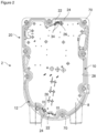
- said first part 2 comprises an edge 20 peripherally delimiting said first housing, marked 10 and this time visible, the cover having been removed in this figure.
- Said housing further comprises a plate 8.
- Said plate 8 is arranged in said first housing 10.
- Said plate 8 is formed, for example, of a printed circuit board carrying various electronic components used, in particular, for controlling the drive motor located in said second housing 6.
- a bottom of the first housing 10 advantageously forms a partition separating the first and second housings 6, 10.
- Said second housing 6 is preferably configured so that the refrigerant circulating in said second housing 6 is in contact with said partition, which makes it possible to evacuate at least part of the heat released by said electronic components located in said first housing 10.
- Said housing further comprises a seal 12, located between said first and second parts 2, 4, to ensure a sealed closure of said first housing 10.
- Said seal 12 comprises, for example, a metal core coated at least partially with an elastomeric material.
- said housing comprises one or more supports 14 for holding said plate 8. Said holding support(s) 14 are arranged in said first housing 10.
- said sealing joint 12 comprises one or more protrusions 22, here two, directed towards the inside of the first housing 10.
- said protrusion or protrusions 22 press on said plate 8 at the level of a contour 24 of said plate 8 to apply said plate 8 to said holding support or supports 14.
- the holding of the plate 8 is reinforced, which makes it possible to limit the risks of vibrations of the free edges of the plate 8 without having to multiply specific members for fixing the plate, such as screws or rivets.
- the protrusions 22 have a limited surface area. Indeed, it is understood that the said holding support(s) 14 are located along said contour 24 of the plate 8.
- the contour 24 of the plate 8 is free over at least part of said contour 24, in particular at the level of said protrusions 22.
- the contour 24 of the plate 8 is free over its entirety and/or fits a wall 28 of said first housing 10, with a slight clearance.
- said protrusion(s) 22 bear on said plate 8 and said plate 8 bears on the holding support(s) 14 in respective bearing zones.
- the support zone(s) of the plate 8 on the holding support(s) 14 and the support zone(s) of the protrusions 22 on the plate 8 are located in line with each other.
- the plate 8 is thus sandwiched between said protrusion(s) 22 and the holding support(s) 14.
- said housing comprises one or more fixing supports 14' for said plate 8.
- Said fixing support(s) 14' are located, in particular, along said contour 24 of the plate 8.
- Said housing comprises, for example, first fixing members 26 for said plate 8, such as a screw, cooperating with said fixing supports 14'.
- Said plate 8 comprises first orifices 30 for the passage of said first fixing members 26.
- the said holding and/or fixing support(s) 14, 14' are here connected to the first part 2, in particular made from the material of the said part 2.
- the said holding and/or fixing support(s) 14, 14' comprise, for example, a pin 16, 16' having a top 18, 18' in contact with the plate 8.
- the top 18 of the pin 16 of the said holding support(s) 14 here forms the support zone of the plate 8 against the said holding support(s).
- the pin 18' of the said fixing support(s) 14' comprises first bores 32 cooperating with the said first fixing members 26.
- said fixing support(s) 14' comprise a pin and a nut, bearing on said pin. Said nut is in contact with said plate. In other words, said plate bears on said nut. Said nut cooperates with said plate fixing members 8.
- said holding support(s) 14 and said fixing support(s) 14' are located at a distance from each other.
- first and second parts 2, 4 are fixed to each other by sandwiching said joint 12 but, except locally, not said plate 8 whose contour 24, as already said, remains preferentially free.
- said protrusion(s) 22 comprise one or more bosses 34 for contact with said plate 8. Said bosses 34 make it easier to press said plate 8 against the holding support(s) 14.
- Said seal 12 has an annular part 36, intended to be sandwiched between the first and second parts 2, 4.
- Said protrusion(s) 34 are situated substantially in the same plane P as said annular part 36, called the plane of the seal.
- Said boss(es) 34 deviate, in particular perpendicularly, from said plane of the seal and have a top, intended to bear on said plate 8. the top of said boss(es) 34 here forms the support zone of the seal 12 against the plate 8.
- the plate 8 is located in a plane P' parallel to the plane of the joint, called the plane of the plate. Said plane P of the joint and said plane P' of the plate are slightly offset from each other in the direction perpendicular to said planes, according to a difference corresponding to a height of said bosses 34.
- said housing further comprises one or more lugs 40 for positioning said seal 12 and/or said plate 8.
- Said seal 12 and/or said plate 8 comprise slots 42, 44 for the passage of the lug(s) 40.
- the passage light(s) 42 of said seal 12 are preferably located at the level of at least one of said protrusions 22, called the mounting protrusion.
- said lug(s) pass through said seal 12 at the level of said protrusion(s) 12.
- Said lug(s) 40 are positioned in specific bores 46 formed in the holding support(s) 14.
- said cover comprises a peripheral skirt 60 intended to form a compression foot of the seal 12 and/or a point excess thickness of material 62, to accommodate said lug 40 at one end of said lug 40 opposite that cooperating with the corresponding holding support 14.
- the protrusion 22 illustrated is the or one of said mounting protrusions. Indeed, it has the or one of the lights 42 of the seal 12.
- Said mounting protrusion present here a free edge 48 provided with a top 50.
- Said light 42 of the seal 12 present at the level of said mounting protrusions is located near said top 50.
- Said bosses 34 are two in number and located along said free edge 48 on either side of said corresponding light 42 of the seal 12, at the level of said mounting protrusion.
- said housing comprises second fixing members, not shown, for said cover on said body, said body comprises second bores cooperating with said second fixing members.
- Said cover comprises second orifices for passage of said second fixing members.
- Said seal 12 comprises third orifices 70 for passage of said second fixing members.
- At least some of said second and third passage orifices, or even all of them, are aligned two by two with one of said second bores so as to leave a passage for one of said second fixing members.
- said protrusions 22 are two in number, arranged opposite each other on either side of said plate 8.
- Said fixing members 26 are also two in number, respectively located near one of said protrusions 22.
Landscapes
- Engineering & Computer Science (AREA)
- Mechanical Engineering (AREA)
- General Engineering & Computer Science (AREA)
- Compressor (AREA)
- Connection Of Plates (AREA)
Applications Claiming Priority (1)
| Application Number | Priority Date | Filing Date | Title |
|---|---|---|---|
| FR2314801A FR3157781A1 (fr) | 2023-12-21 | 2023-12-21 | boîtier et un compresseur muni d’un tel boîtier, notamment, pour véhicule automobile |
Publications (2)
| Publication Number | Publication Date |
|---|---|
| EP4575228A1 true EP4575228A1 (de) | 2025-06-25 |
| EP4575228B1 EP4575228B1 (de) | 2026-02-04 |
Family
ID=91072966
Family Applications (1)
| Application Number | Title | Priority Date | Filing Date |
|---|---|---|---|
| EP24218997.5A Active EP4575228B1 (de) | 2023-12-21 | 2024-12-11 | Gehäuse und verdichter mit einem solchen gehäuse, insbesondere für ein kraftfahrzeug |
Country Status (2)
| Country | Link |
|---|---|
| EP (1) | EP4575228B1 (de) |
| FR (1) | FR3157781A1 (de) |
Citations (4)
| Publication number | Priority date | Publication date | Assignee | Title |
|---|---|---|---|---|
| EP1039791B1 (de) * | 1999-03-26 | 2004-10-06 | Siemens VDO Automotive S.A.S. | Elektronikgehäuse |
| US20050048850A1 (en) * | 2003-08-29 | 2005-03-03 | Hirschmann Electronics Gmbh & Co. Kg | Sandwich housing for an antenna amplifier |
| DE102015116052A1 (de) * | 2014-09-30 | 2016-03-31 | Kabushiki Kaisha Toyota Jidoshokki | Elektrischer Verdichter |
| WO2023202923A1 (de) * | 2022-04-19 | 2023-10-26 | Phoenix Contact Gmbh & Co. Kg | Elektronikgehäuse |
-
2023
- 2023-12-21 FR FR2314801A patent/FR3157781A1/fr active Pending
-
2024
- 2024-12-11 EP EP24218997.5A patent/EP4575228B1/de active Active
Patent Citations (4)
| Publication number | Priority date | Publication date | Assignee | Title |
|---|---|---|---|---|
| EP1039791B1 (de) * | 1999-03-26 | 2004-10-06 | Siemens VDO Automotive S.A.S. | Elektronikgehäuse |
| US20050048850A1 (en) * | 2003-08-29 | 2005-03-03 | Hirschmann Electronics Gmbh & Co. Kg | Sandwich housing for an antenna amplifier |
| DE102015116052A1 (de) * | 2014-09-30 | 2016-03-31 | Kabushiki Kaisha Toyota Jidoshokki | Elektrischer Verdichter |
| WO2023202923A1 (de) * | 2022-04-19 | 2023-10-26 | Phoenix Contact Gmbh & Co. Kg | Elektronikgehäuse |
Also Published As
| Publication number | Publication date |
|---|---|
| FR3157781A1 (fr) | 2025-06-27 |
| EP4575228B1 (de) | 2026-02-04 |
Similar Documents
| Publication | Publication Date | Title |
|---|---|---|
| FR2724880A1 (fr) | Actionneur comprenant un carter, notamment pour un embrayage de vehicule automobile | |
| EP0681110A1 (de) | Verbesserte Käfigmutter | |
| FR2712042A1 (fr) | Moteur oscillant hydraulique. | |
| EP0942155A1 (de) | Brennkraftmaschine mit Anti-Schaumvorrichtung | |
| FR2900687A1 (fr) | Carter d'huile pour moteur a combustion interne | |
| EP4575228A1 (de) | Gehäuse und verdichter mit einem solchen gehäuse, insbesondere für ein kraftfahrzeug | |
| FR3043878A1 (fr) | Boitier a dispositif de controle integre et compresseur electrique comprenant ledit boitier | |
| FR3015015A1 (fr) | Echangeur de chaleur comprenant un faisceau muni de moyens permettant de limiter les mouvements dudit faisceau d'echange par rapport aux parois du boitier | |
| FR3116039A1 (fr) | Carter d’un dispositif de système de direction assistée muni d’un couvercle | |
| EP0625636B1 (de) | Hohles metallisches Element mit Abdichtung, z.B. Ölwanne für eine Brennkraftmaschine | |
| FR2475139A1 (fr) | Ensemble d'alimentation en carburant | |
| WO2020057980A1 (fr) | Dispositif de transmission de couple hybride desalignee | |
| FR3100868A1 (fr) | Elément d’obturation pour projecteur d’un véhicule automobile | |
| EP4617509A1 (de) | Kühlvorrichtung für ein leistungsmodul | |
| FR3065838A1 (fr) | Module de commande pour compresseur electrique | |
| EP3526461B1 (de) | Kühlmitteldeflektor | |
| EP4618707A1 (de) | Kühlvorrichtung für ein leistungsmodul | |
| FR2529514A1 (fr) | Boitier pour un equipement de chauffage ou de climatisation d'un vehicule automobile | |
| EP1239711A1 (de) | Elektronikgehäuse sonder Deckel | |
| WO2026087458A1 (fr) | Carter de machine electrique | |
| EP4361472A1 (de) | Dichtungsvorrichtung, anordnung und fahrzeug mit solch einer dichtungsvorrichtung und verfahren zur montage eines fahrzeugs mit solch einer dichtungsvorrichtung | |
| EP1258382A1 (de) | Bausatz für Hydraulikantrieb und mit einem solchen Bausatz versehener Fahrzeugmotor | |
| FR3043734B1 (fr) | Boitier a dispositif de controle integre et compresseur electrique comprenant ledit boitier | |
| FR2900452A1 (fr) | Assemblage d'un reservoir sur un support rigide | |
| FR2819546A1 (fr) | Boitier de filtre a etancheite axiale et radiale |
Legal Events
| Date | Code | Title | Description |
|---|---|---|---|
| PUAI | Public reference made under article 153(3) epc to a published international application that has entered the european phase |
Free format text: ORIGINAL CODE: 0009012 |
|
| STAA | Information on the status of an ep patent application or granted ep patent |
Free format text: STATUS: REQUEST FOR EXAMINATION WAS MADE |
|
| 17P | Request for examination filed |
Effective date: 20241211 |
|
| AK | Designated contracting states |
Kind code of ref document: A1 Designated state(s): AL AT BE BG CH CY CZ DE DK EE ES FI FR GB GR HR HU IE IS IT LI LT LU LV MC ME MK MT NL NO PL PT RO RS SE SI SK SM TR |
|
| GRAP | Despatch of communication of intention to grant a patent |
Free format text: ORIGINAL CODE: EPIDOSNIGR1 |
|
| STAA | Information on the status of an ep patent application or granted ep patent |
Free format text: STATUS: GRANT OF PATENT IS INTENDED |
|
| INTG | Intention to grant announced |
Effective date: 20250806 |
|
| GRAS | Grant fee paid |
Free format text: ORIGINAL CODE: EPIDOSNIGR3 |
|
| GRAA | (expected) grant |
Free format text: ORIGINAL CODE: 0009210 |
|
| STAA | Information on the status of an ep patent application or granted ep patent |
Free format text: STATUS: THE PATENT HAS BEEN GRANTED |
|
| AK | Designated contracting states |
Kind code of ref document: B1 Designated state(s): AL AT BE BG CH CY CZ DE DK EE ES FI FR GB GR HR HU IE IS IT LI LT LU LV MC ME MK MT NL NO PL PT RO RS SE SI SK SM TR |
|
| REG | Reference to a national code |
Ref country code: CH Ref legal event code: F10 Free format text: ST27 STATUS EVENT CODE: U-0-0-F10-F00 (AS PROVIDED BY THE NATIONAL OFFICE) Effective date: 20260204 Ref country code: GB Ref legal event code: FG4D Free format text: NOT ENGLISH |
|
| REG | Reference to a national code |
Ref country code: DE Ref legal event code: R096 Ref document number: 602024002413 Country of ref document: DE |
|
| REG | Reference to a national code |
Ref country code: IE Ref legal event code: FG4D Free format text: LANGUAGE OF EP DOCUMENT: FRENCH |
|
| REG | Reference to a national code |
Ref country code: CH Ref legal event code: W10 Free format text: ST27 STATUS EVENT CODE: U-0-0-W10-W00 (AS PROVIDED BY THE NATIONAL OFFICE) Effective date: 20260311 |
|
| RAP2 | Party data changed (patent owner data changed or rights of a patent transferred) |
Owner name: VALEO ELECTRIFICATION |