EP4575246A1 - Connecteur modulaire pour arbre de transmission automobile - Google Patents
Connecteur modulaire pour arbre de transmission automobile Download PDFInfo
- Publication number
- EP4575246A1 EP4575246A1 EP24461644.7A EP24461644A EP4575246A1 EP 4575246 A1 EP4575246 A1 EP 4575246A1 EP 24461644 A EP24461644 A EP 24461644A EP 4575246 A1 EP4575246 A1 EP 4575246A1
- Authority
- EP
- European Patent Office
- Prior art keywords
- connector
- tube
- drive shaft
- insert
- aluminum
- Prior art date
- Legal status (The legal status is an assumption and is not a legal conclusion. Google has not performed a legal analysis and makes no representation as to the accuracy of the status listed.)
- Pending
Links
Images


Classifications
-
- F—MECHANICAL ENGINEERING; LIGHTING; HEATING; WEAPONS; BLASTING
- F16—ENGINEERING ELEMENTS AND UNITS; GENERAL MEASURES FOR PRODUCING AND MAINTAINING EFFECTIVE FUNCTIONING OF MACHINES OR INSTALLATIONS; THERMAL INSULATION IN GENERAL
- F16D—COUPLINGS FOR TRANSMITTING ROTATION; CLUTCHES; BRAKES
- F16D1/00—Couplings for rigidly connecting two coaxial shafts or other movable machine elements
- F16D1/06—Couplings for rigidly connecting two coaxial shafts or other movable machine elements for attachment of a member on a shaft or on a shaft-end
- F16D1/064—Couplings for rigidly connecting two coaxial shafts or other movable machine elements for attachment of a member on a shaft or on a shaft-end non-disconnectable
- F16D1/068—Couplings for rigidly connecting two coaxial shafts or other movable machine elements for attachment of a member on a shaft or on a shaft-end non-disconnectable involving gluing, welding or the like
-
- F—MECHANICAL ENGINEERING; LIGHTING; HEATING; WEAPONS; BLASTING
- F16—ENGINEERING ELEMENTS AND UNITS; GENERAL MEASURES FOR PRODUCING AND MAINTAINING EFFECTIVE FUNCTIONING OF MACHINES OR INSTALLATIONS; THERMAL INSULATION IN GENERAL
- F16C—SHAFTS; FLEXIBLE SHAFTS; ELEMENTS OR CRANKSHAFT MECHANISMS; ROTARY BODIES OTHER THAN GEARING ELEMENTS; BEARINGS
- F16C3/00—Shafts; Axles; Cranks; Eccentrics
- F16C3/02—Shafts; Axles
- F16C3/026—Shafts made of fibre reinforced resin
-
- F—MECHANICAL ENGINEERING; LIGHTING; HEATING; WEAPONS; BLASTING
- F16—ENGINEERING ELEMENTS AND UNITS; GENERAL MEASURES FOR PRODUCING AND MAINTAINING EFFECTIVE FUNCTIONING OF MACHINES OR INSTALLATIONS; THERMAL INSULATION IN GENERAL
- F16C—SHAFTS; FLEXIBLE SHAFTS; ELEMENTS OR CRANKSHAFT MECHANISMS; ROTARY BODIES OTHER THAN GEARING ELEMENTS; BEARINGS
- F16C3/00—Shafts; Axles; Cranks; Eccentrics
- F16C3/02—Shafts; Axles
- F16C3/023—Shafts; Axles made of several parts, e.g. by welding
-
- F—MECHANICAL ENGINEERING; LIGHTING; HEATING; WEAPONS; BLASTING
- F16—ENGINEERING ELEMENTS AND UNITS; GENERAL MEASURES FOR PRODUCING AND MAINTAINING EFFECTIVE FUNCTIONING OF MACHINES OR INSTALLATIONS; THERMAL INSULATION IN GENERAL
- F16D—COUPLINGS FOR TRANSMITTING ROTATION; CLUTCHES; BRAKES
- F16D1/00—Couplings for rigidly connecting two coaxial shafts or other movable machine elements
- F16D1/06—Couplings for rigidly connecting two coaxial shafts or other movable machine elements for attachment of a member on a shaft or on a shaft-end
- F16D1/064—Couplings for rigidly connecting two coaxial shafts or other movable machine elements for attachment of a member on a shaft or on a shaft-end non-disconnectable
- F16D1/072—Couplings for rigidly connecting two coaxial shafts or other movable machine elements for attachment of a member on a shaft or on a shaft-end non-disconnectable involving plastic deformation
-
- F—MECHANICAL ENGINEERING; LIGHTING; HEATING; WEAPONS; BLASTING
- F16—ENGINEERING ELEMENTS AND UNITS; GENERAL MEASURES FOR PRODUCING AND MAINTAINING EFFECTIVE FUNCTIONING OF MACHINES OR INSTALLATIONS; THERMAL INSULATION IN GENERAL
- F16C—SHAFTS; FLEXIBLE SHAFTS; ELEMENTS OR CRANKSHAFT MECHANISMS; ROTARY BODIES OTHER THAN GEARING ELEMENTS; BEARINGS
- F16C2204/00—Metallic materials; Alloys
- F16C2204/20—Alloys based on aluminium
-
- F—MECHANICAL ENGINEERING; LIGHTING; HEATING; WEAPONS; BLASTING
- F16—ENGINEERING ELEMENTS AND UNITS; GENERAL MEASURES FOR PRODUCING AND MAINTAINING EFFECTIVE FUNCTIONING OF MACHINES OR INSTALLATIONS; THERMAL INSULATION IN GENERAL
- F16C—SHAFTS; FLEXIBLE SHAFTS; ELEMENTS OR CRANKSHAFT MECHANISMS; ROTARY BODIES OTHER THAN GEARING ELEMENTS; BEARINGS
- F16C2204/00—Metallic materials; Alloys
- F16C2204/60—Ferrous alloys, e.g. steel alloys
-
- F—MECHANICAL ENGINEERING; LIGHTING; HEATING; WEAPONS; BLASTING
- F16—ENGINEERING ELEMENTS AND UNITS; GENERAL MEASURES FOR PRODUCING AND MAINTAINING EFFECTIVE FUNCTIONING OF MACHINES OR INSTALLATIONS; THERMAL INSULATION IN GENERAL
- F16C—SHAFTS; FLEXIBLE SHAFTS; ELEMENTS OR CRANKSHAFT MECHANISMS; ROTARY BODIES OTHER THAN GEARING ELEMENTS; BEARINGS
- F16C2226/00—Joining parts; Fastening; Assembling or mounting parts
- F16C2226/10—Force connections, e.g. clamping
- F16C2226/12—Force connections, e.g. clamping by press-fit, e.g. plug-in
-
- F—MECHANICAL ENGINEERING; LIGHTING; HEATING; WEAPONS; BLASTING
- F16—ENGINEERING ELEMENTS AND UNITS; GENERAL MEASURES FOR PRODUCING AND MAINTAINING EFFECTIVE FUNCTIONING OF MACHINES OR INSTALLATIONS; THERMAL INSULATION IN GENERAL
- F16C—SHAFTS; FLEXIBLE SHAFTS; ELEMENTS OR CRANKSHAFT MECHANISMS; ROTARY BODIES OTHER THAN GEARING ELEMENTS; BEARINGS
- F16C2226/00—Joining parts; Fastening; Assembling or mounting parts
- F16C2226/30—Material joints
- F16C2226/36—Material joints by welding
-
- F—MECHANICAL ENGINEERING; LIGHTING; HEATING; WEAPONS; BLASTING
- F16—ENGINEERING ELEMENTS AND UNITS; GENERAL MEASURES FOR PRODUCING AND MAINTAINING EFFECTIVE FUNCTIONING OF MACHINES OR INSTALLATIONS; THERMAL INSULATION IN GENERAL
- F16C—SHAFTS; FLEXIBLE SHAFTS; ELEMENTS OR CRANKSHAFT MECHANISMS; ROTARY BODIES OTHER THAN GEARING ELEMENTS; BEARINGS
- F16C2226/00—Joining parts; Fastening; Assembling or mounting parts
- F16C2226/30—Material joints
- F16C2226/40—Material joints with adhesive
-
- F—MECHANICAL ENGINEERING; LIGHTING; HEATING; WEAPONS; BLASTING
- F16—ENGINEERING ELEMENTS AND UNITS; GENERAL MEASURES FOR PRODUCING AND MAINTAINING EFFECTIVE FUNCTIONING OF MACHINES OR INSTALLATIONS; THERMAL INSULATION IN GENERAL
- F16C—SHAFTS; FLEXIBLE SHAFTS; ELEMENTS OR CRANKSHAFT MECHANISMS; ROTARY BODIES OTHER THAN GEARING ELEMENTS; BEARINGS
- F16C2226/00—Joining parts; Fastening; Assembling or mounting parts
- F16C2226/50—Positive connections
- F16C2226/60—Positive connections with threaded parts, e.g. bolt and nut connections
-
- F—MECHANICAL ENGINEERING; LIGHTING; HEATING; WEAPONS; BLASTING
- F16—ENGINEERING ELEMENTS AND UNITS; GENERAL MEASURES FOR PRODUCING AND MAINTAINING EFFECTIVE FUNCTIONING OF MACHINES OR INSTALLATIONS; THERMAL INSULATION IN GENERAL
- F16C—SHAFTS; FLEXIBLE SHAFTS; ELEMENTS OR CRANKSHAFT MECHANISMS; ROTARY BODIES OTHER THAN GEARING ELEMENTS; BEARINGS
- F16C2226/00—Joining parts; Fastening; Assembling or mounting parts
- F16C2226/50—Positive connections
- F16C2226/70—Positive connections with complementary interlocking parts
- F16C2226/72—Positive connections with complementary interlocking parts with bayonet joints, i.e. parts are rotated to create positive interlock
-
- F—MECHANICAL ENGINEERING; LIGHTING; HEATING; WEAPONS; BLASTING
- F16—ENGINEERING ELEMENTS AND UNITS; GENERAL MEASURES FOR PRODUCING AND MAINTAINING EFFECTIVE FUNCTIONING OF MACHINES OR INSTALLATIONS; THERMAL INSULATION IN GENERAL
- F16C—SHAFTS; FLEXIBLE SHAFTS; ELEMENTS OR CRANKSHAFT MECHANISMS; ROTARY BODIES OTHER THAN GEARING ELEMENTS; BEARINGS
- F16C2326/00—Articles relating to transporting
- F16C2326/01—Parts of vehicles in general
- F16C2326/06—Drive shafts
-
- F—MECHANICAL ENGINEERING; LIGHTING; HEATING; WEAPONS; BLASTING
- F16—ENGINEERING ELEMENTS AND UNITS; GENERAL MEASURES FOR PRODUCING AND MAINTAINING EFFECTIVE FUNCTIONING OF MACHINES OR INSTALLATIONS; THERMAL INSULATION IN GENERAL
- F16D—COUPLINGS FOR TRANSMITTING ROTATION; CLUTCHES; BRAKES
- F16D2200/00—Materials; Production methods therefor
- F16D2200/0004—Materials; Production methods therefor metallic
- F16D2200/0008—Ferro
- F16D2200/0021—Steel
-
- F—MECHANICAL ENGINEERING; LIGHTING; HEATING; WEAPONS; BLASTING
- F16—ENGINEERING ELEMENTS AND UNITS; GENERAL MEASURES FOR PRODUCING AND MAINTAINING EFFECTIVE FUNCTIONING OF MACHINES OR INSTALLATIONS; THERMAL INSULATION IN GENERAL
- F16D—COUPLINGS FOR TRANSMITTING ROTATION; CLUTCHES; BRAKES
- F16D2200/00—Materials; Production methods therefor
- F16D2200/0004—Materials; Production methods therefor metallic
- F16D2200/0026—Non-ferro
- F16D2200/003—Light metals, e.g. aluminium
-
- F—MECHANICAL ENGINEERING; LIGHTING; HEATING; WEAPONS; BLASTING
- F16—ENGINEERING ELEMENTS AND UNITS; GENERAL MEASURES FOR PRODUCING AND MAINTAINING EFFECTIVE FUNCTIONING OF MACHINES OR INSTALLATIONS; THERMAL INSULATION IN GENERAL
- F16D—COUPLINGS FOR TRANSMITTING ROTATION; CLUTCHES; BRAKES
- F16D2250/00—Manufacturing; Assembly
- F16D2250/0061—Joining
- F16D2250/0069—Adhesive bonding
-
- F—MECHANICAL ENGINEERING; LIGHTING; HEATING; WEAPONS; BLASTING
- F16—ENGINEERING ELEMENTS AND UNITS; GENERAL MEASURES FOR PRODUCING AND MAINTAINING EFFECTIVE FUNCTIONING OF MACHINES OR INSTALLATIONS; THERMAL INSULATION IN GENERAL
- F16D—COUPLINGS FOR TRANSMITTING ROTATION; CLUTCHES; BRAKES
- F16D2250/00—Manufacturing; Assembly
- F16D2250/0061—Joining
- F16D2250/0076—Welding, brazing
-
- F—MECHANICAL ENGINEERING; LIGHTING; HEATING; WEAPONS; BLASTING
- F16—ENGINEERING ELEMENTS AND UNITS; GENERAL MEASURES FOR PRODUCING AND MAINTAINING EFFECTIVE FUNCTIONING OF MACHINES OR INSTALLATIONS; THERMAL INSULATION IN GENERAL
- F16D—COUPLINGS FOR TRANSMITTING ROTATION; CLUTCHES; BRAKES
- F16D2250/00—Manufacturing; Assembly
- F16D2250/0084—Assembly or disassembly
-
- F—MECHANICAL ENGINEERING; LIGHTING; HEATING; WEAPONS; BLASTING
- F16—ENGINEERING ELEMENTS AND UNITS; GENERAL MEASURES FOR PRODUCING AND MAINTAINING EFFECTIVE FUNCTIONING OF MACHINES OR INSTALLATIONS; THERMAL INSULATION IN GENERAL
- F16D—COUPLINGS FOR TRANSMITTING ROTATION; CLUTCHES; BRAKES
- F16D2300/00—Special features for couplings or clutches
- F16D2300/12—Mounting or assembling
Definitions
- the invention applies to a modular connector for an automotive drive shaft.
- the invention also pertains to a drive shaft containing the aforementioned connector.
- the invention concerns the design of an automotive drive shaft reinforced with carbon fiber composite in the area of attachment of a mounting component placed at the end of the shaft to the carbon fiber tube.
- the mounting component may serve as a pipe connector, a sliding joint, a spline joint shaft, a tripod joint for a flexible coupling, or a splined shaft with bearing support for the shaft. This solution is applicable in the automotive industry.
- Drive shafts are rotating components in various machines and vehicles, operating at different speeds.
- Drive shafts are used to transfer torque from the engine to the drivetrain system, such as the gearbox, differential, and wheels, enabling the vehicle to move.
- Drive shafts typically include elements such as cross joints, homokinetic joints, sliding couplings, intermediate couplings, and flexible connectors.
- the drive shaft is constructed from a cylindrical tube with a circular cross-section. The shape of the shaft affects its strength and ride comfort. Rotating components without an appropriate streamlined shape can cause unwanted noises, which may reduce the comfort during travel.
- the solution according to the invention pertains to a connector that enables efficient and durable coupling of an aluminum or carbon tube with a steel mounting component, such as a shaft, and with an aluminum insert featuring internal profiling.
- the key element of the invention is a securing system for the connections using fixing screws with Schnorr washers, which provides additional reinforcement and stability during operation.
- This connection can be applied to aluminum shafts, where the connector is welded to the aluminum shaft tube, as well as to composite shafts, such as carbon fiber shafts, where the connector insert can be bonded to the carbon tube using adhesive.
- the invention allows for weight reduction and facilitates easy disassembly and replacement of components in the event of a failure.
- elastomeric seals around the polygonal ball neck protect sensitive elements within a lubricated chamber.
- the disclosed coupling device enables the transmission of high torque loads and complex rotational motions between elements, even in the presence of misalignment. Its flexible design allows for greater layout freedom and increases tolerance to assembly errors.
- the combination of the "ball-and-socket" system, sliding plates, and elastomeric seals ensures efficient and reliable torque transfer while protecting sensitive components. This solution is suitable for applications requiring high precision and resistance to misalignment, such as in machinery, automotive, or energy industries.
- U.S. patent application no. US2002032065 AA describes a drive shaft construction that enhances the connection between the main shaft body and the yoke. It uses serrated inserts and matching grooves to create a stronger and more secure connection.
- the production method for this drive shaft involves a press-fit assembly stage followed by a withdrawal stage to ensure proper assembly and alignment.
- This application utilizes a knurling technique on the outer surface of the insert to be pressed into the composite tube. The specific shape and height of the knurling profile aim to lock the insert during pressing and prevent rotation during shaft operation.
- my solution avoids knurling and the cylindrical shape inside the tube, which does not fully address the issue of delamination of the carbon fiber layers within the tube.
- the strength is enhanced, and the insert's rotation is physically blocked.
- the Chinese utility model description CN205315467 U discloses a drive shaft made of carbon fiber composite, consisting of a tube with pipe joints at both ends. One of the pipe joints is connected via a cross joint to a sliding sleeve. The other end of the drive shaft includes a flange joint, a cross joint, and a pipe joint embedded within the tube.
- the drive shaft tube is made from a carbon fiber composite material, combining carbon fibers and epoxy resin, providing high strength and durability, making the drive shaft more efficient and reliable.
- the utility model relies on joining a circular tube with a circular pipe joint through press-fit and/or adhesive bonding. However, the circular-to-circular connection does not eliminate the issue of delamination of carbon fiber between the respective layers of the tube. Delamination would prevent torque transfer between the driving and driven components. Using a polygonal connection solves this problem, as delamination at the tube ends becomes impossible due to the physical blocking of fiber displacement within the composite tube.
- the U.S. patent application US20230143202 A1 describes a pipe joint as a mounting component used in vehicles for power transmission from the engine to the wheels.
- the invention concerns a pipe joint used in the drive shaft, which is connected to the drive shaft tube through adhesive bonding or tight fitting.
- the tubular yoke is made from a pre-preg composite material, which is strong and lightweight. This material improves the performance and durability of the drive shaft.
- a sliding joint consists of a sleeve and a splined shaft.
- male and female locks are primarily used to mount the drive shaft to the gearbox and differential to transfer drive and establish a centering position for the shaft.
- Drive shafts consist of a tube and side components attached to it. Tubes, rather than solid rods, are used because shafts are not solid in cross-section like rods. Torque transmission using a direct lock within a carbon fiber tube is practically impossible. This would require a lock to be screwed using screws threaded into a thick-walled composite tube. However, using such a lock is unfeasible due to the disruption of the composite tube structure during drilling. Threads are not directly made in composite tubes; instead, special steel sleeves with internal threads are pressed or bonded in place. The purpose of locks in joining two components is to center them, not to transfer torque between a composite tube and an inserted or pressed-in insert.
- the element with a lock is connected to the steel tube by welding, brazing, or splines. Forming precise splines in a composite tube during its winding is impossible due to the nature of the fiber and the inability to achieve sharp or straight angles. Most methods known for steel tubes cannot be used for production and processing of composite tubes.
- the invention aimed to develop a new universal drive shaft connector that enables the connection of an aluminum or carbon tube with a mounting component, such as a steel shaft, while achieving maximum weight reduction of the system and maintaining optimal strength parameters of the entire shaft. This is particularly intended for use in high-power and high-torque vehicles while ensuring an aerodynamic shaft shape that guarantees high user comfort and eliminates noise. Another goal was to enable the connection of steel execution elements with aluminum drive shaft tubes.
- the invention also aimed to produce a carbon fiber shaft with increased resistance to delamination between the fiber layers and the insert of the mounting component. The design sought to ensure that the torque would be transmitted across the entire cross-section of the carbon tube rather than progressively between layers, as is typical in round insert-to-tube connections. Additionally, the solution was intended to prevent drive loss in the event of insert loosening and to allow for both tight and loose fitting during assembly, with the possibility of utilizing adhesive bonding for the connection.
- the inclusion of recesses with screw holes in the modular drive shaft connector ensures stable and secure fastening to the mounting component and enhances its durability.
- the screw holes enable precise attachment of the mounting component, contributing to improved torque transmission and minimizing the risk of loosening during operation.
- This type of fastening prevents shifting or loosening under dynamic load conditions.
- Additional fastening via screws facilitates more effective transmission of driving forces without energy loss due to mismatches or loose connections, resulting in reduced vibrations and noise levels during drive shaft operation.
- the modular connection using screws allows for easier disassembly and replacement of components during servicing, reducing downtime and streamlining maintenance. The reliability and durability of this solution improve performance and extend the lifespan of the entire drivetrain system. Using aluminum for the connector reduces the overall weight of the system.
- the technical effect of using a profiled socket shaped as a regular polygon inscribed in a circle, particularly one with 12 to 14 sides, is the optimization of torque transmission and increased reliability of the automotive drive shaft connection.
- a profile better distributes the forces acting on the connection, reducing the risk of excessive wear and damage during operation.
- a polygon with a higher number of sides (especially 14 sides) allows for more uniform force transfer between contact surfaces, thereby reducing stresses and limiting localized loads.
- the regular polygon ensures a stable connection and improves assembly precision, minimizing play and vibrations, and particularly maintaining alignment between components. With even force distribution, the joint is more resistant to wear and material fatigue, increasing its lifespan.
- the profiling also simplifies the assembly and disassembly of components, which can reduce maintenance time.
- the modular connector's attachment on the drive shaft tube side is in the form of a recess designed for welding the drive shaft tube, preferably the mount and the tube are made of aluminum. It is particularly preferably if both the shaft tube and the connector mount are made of aluminum, in which case the connector can be welded to the shaft after the mounting component is preassembled onto the connector.
- the effect of using a recess-style mount for the drive shaft connector, designed for welding an aluminum drive shaft tube, is the achievement of a durable, lightweight, and precisely fitted connection between the connector and the shaft.
- the recess ensures proper seating of the tube, enhancing the connection's stability and minimizing the risk of deformation or shifting during operation.
- the recess provides a contact surface tailored to the tube, enabling a strong bond during welding.
- Aluminum's lower density reduces the total weight of the structure while maintaining high strength.
- Using aluminum for the attached drive shaft tube reduces the overall weight of the system.
- Aluminum's natural resistance to corrosion extends the lifespan of the drivetrain components and decreases maintenance requirements.
- the recess allows for more precise seating of the tube and simplifies the welding process, shortening assembly time and improving its quality.
- the mounting of the modular automotive drive shaft connector on the drive shaft tube side is additionally equipped with an insert adapted for attaching the drive shaft tube, preferably made of aluminum or composite material, such as carbon fiber.
- the application of a mounting insert in the automotive connector allows for the joining of a steel or aluminum element with a composite tube.
- the insert can be either circular or profiled, depending on the shape of the ends of the aluminum or carbon tube.
- An aluminum insert and a carbon shaft tube significantly reduce the weight of the structure, which translates to less engine load, lower fuel consumption, and improved vehicle dynamics.
- Carbon fiber offers an excellent strength-to-weight ratio, enabling the transmission of high loads without deformation, thereby increasing the precision and reliability of the connection.
- Composite materials like carbon fiber also have vibration-damping properties, reducing noise and vibrations in the drivetrain and improving ride comfort and stability.
- Composites, especially carbon fiber are resistant to corrosion and material fatigue, extending the connection's lifespan and reducing the need for frequent replacements and maintenance.
- Reduced weight and increased rigidity of the drivetrain improve acceleration and vehicle maneuverability, which is particularly beneficial for sports and high-end vehicles.
- the insert has a cylindrical shape and is equipped with at least two centering rings with a circular cross-section.
- the insert of the modular automotive drive shaft connector has a shape approximating a cylinder and is equipped with at least one centering ring with a cross-section in the form of a substantially regular polygon with 8 to 20 sides.
- the shape of the connector's insert corresponds to the shape of the mounting sleeve inside the tube and is configured so that the connector with the insert is secured to the tube's mounting sleeve using either a tight fit and/or adhesive bonding.
- the centering ring of the automotive drive shaft insert has a cross-section in the shape of a regular polygon with 12 to 14 sides, most preferably 12 sides.
- the insert of the modular automotive drive shaft connector contains at least two centering rings, with a section of the insert between the centering rings having a reduced profile that forms a chamber for adhesive application when inserted into the tube.
- the use of two centering rings allows for the creation of a chamber between the insert and the tube, enabling the space to be filled with adhesive bonding.
- This configuration permits the use of either a tightly fitted insert or a press-fitted insert additionally secured with adhesive. Combining these two methods increases safety and prevents the insert from detaching from the composite tube.
- Drive shafts are subjected to various forces transmitted from the driving component to the driven component. Misalignment between mounting elements significantly impacts the drive shaft's performance and lifespan.
- the adhesive ensures a permanent bond between the tube surface and the insert surface, preventing any displacement.
- the invention pertains to an automotive drive shaft characterized by a modular connector according to the invention, with the drive shaft tube made of aluminum permanently attached to the connector via welding or adhesive bonding, and a mounting component immovably and detachably connected to the connector.
- the automotive drive shaft tube includes an opening for injecting adhesive into the chamber formed by the reduced-profile section of the insert and the tube's internal lateral wall, preferably two openings symmetrically placed on opposite sides of the tube.
- the mounting component is a splined shaft for a joint, a splined shaft with bearing support for the drive shaft, a sliding joint, or a flexible joint yoke, and is preferably made of steel.
- a connector with a mounting insert in a carbon tube enables the construction of various drive shaft designs depending on specific requirements. This solution allows the creation of short, long, segmented shafts, shafts designed to operate at increased angles, and shafts with extended operational ranges.
- the advantage of the invention is its applicability to any type of drive shaft, including tubular joints, flange joints, splined shafts for joints, intermediate shafts used for mounting drive shaft supports, as well as sliding joints that allow the drive shaft to extend and retract during suspension operation.
- Each of the aforementioned components can be manufactured or adapted to include a mounting element with an insert corresponding to the shape of the carbon tube's mounting sleeve. It is also possible to adapt pre-made drive shaft components into a form that allows connection without welding or fusing.
- the first embodiment involves a universal automotive drive shaft connector (1) in the form of a ring made of aluminum.
- the connector can also be made of another metal; however, using aluminum offers the advantage of reducing the weight of the shaft and, in the case of aluminum tubes (4), enabling them to be welded to the connector (1).
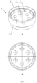
- the connector (1) features a mounting section (2) on the functional side to accommodate a matching-shaped mounting component (7), while the opposite side includes a mounting section (3) for the drive shaft tube (4), which in this case is in the form of a recess with a diameter tailored to the drive shaft tube (4).
- the mounting component (7) can be made from various materials. Typically, steel is used due to its good strength properties at a competitive cost. However, depending on the drive shaft's application, other materials such as titanium may also be used.
- the two components are fastened together, for example, with screws (18) passing through the screw holes (6) in the connector (1).
- the arrangement of the screw holes (6) in the connector (1) corresponds to the arrangement of threaded holes (9) in the mount (8) of the mounting component (7).
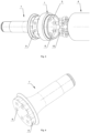
- Fig. 8 provides a side view of the automotive drive shaft, which consists of three components: the connector (1) and the mounting component (7) prior to being welded to the aluminum tube (4) (A), and the connector (1) with the mounting component (7) welded to the aluminum tube (4) (B).
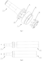
- the third embodiment presents an automotive drive shaft connector (1) with an insert (11) featuring two centering rings (12, 14) with a cylindrical shape and a reduced-profile section (13) located between them.
- the connector (1) is equipped with screw holes (6) for securing the mounting component (7) with screws (18).
- the connector includes a recess (5) in the form of a partition equipped with screw holes (6) for the screws (18).
- alternatives to screwed connections (18) can also be used in similar applications.
- the automotive drive shaft connector (1) in the fourth exemplary embodiment, illustrated in Figs. 10 and 11 is equipped with an insert (11) featuring two profiled centering rings (12, 14) with a shape approximating a cylinder and a reduced-profile section (13) located between the rings (12, 14).
- This reduced-profile section (13) can be profiled or circular.
- the connector (1) also includes screw holes (6) located in a recess (5) in the form of a partition.
- Table 1 presents the results of the tests evaluating various functional parameters of the solutions, including mechanical strength, shape cylindricity, production difficulty, risk of rotation within the tube (15), risk of tube (15) fracture at the polygonal edges, imperfections in the carbon fiber structure during winding, flexibility in adjusting the tube (15) thickness while maintaining a cylindrical shape, the amount of fiber required to achieve a cylindrical shape, production cost, production time, wall thickness from the polygon vertex to the tube's (15) outer diameter, and the potential for rotation between layers.
- Table 1 presents the results of the tests evaluating various functional parameters of the solutions, including mechanical strength, shape
- Fig. 16 illustrates a drive shaft composed of a connector (1) with an insert (11) and a tube (15) reinforced with carbon fiber.
- the carbon fiber tube (15) has a radius of 35 mm, and at the ends of the tube (15), there are two mounting components (7) - a splined joint shaft (shown on the left side of Fig. 13 ) and a tubular joint (shown on the right side of Fig. 13 ).
- Each mounting component (7) includes a body (10) connected to the connector (1), which is equipped with an insert (11) in a shape approximating a cylinder, with a length of 120 mm, though the length of the insert (11) can vary and is typically in the range of 40 to 140 mm.
- the first centering ring (12) is located near the connector (1), while the second centering ring (14) is at the end of the cylindrical extension of the insert (11). Between the centering rings (12, 14) is a zone with a smaller diameter (13), reduced by 0.2 to 2 mm compared to the diameter of the centering rings (12, 14).
- the insert (11) of the connector (1) is secured to the mounting sleeve (16) of the carbon fiber (composite) tube (15) using a tight fit of the centering rings (12, 14) and adhesive bonding. Once the insert (11) is placed in the mounting sleeve (16) of matching shape inside the tube (15), an adhesive chamber is formed. The adhesive is applied directly to the insert (11) before it is inserted into the tube (15).
- the side wall of the carbon fiber tube (15) is equipped with one or more holes (17), preferably two holes (17) symmetrically located on opposite sides of the tube (15).
- the adhesive is injected through one of the holes (17) into the adhesive chamber. Once the chamber is filled with adhesive, any excess exits through the hole (17) on the opposite side.
Landscapes
- Engineering & Computer Science (AREA)
- General Engineering & Computer Science (AREA)
- Mechanical Engineering (AREA)
- Ocean & Marine Engineering (AREA)
- Shafts, Cranks, Connecting Bars, And Related Bearings (AREA)
- Motor Power Transmission Devices (AREA)
Applications Claiming Priority (1)
| Application Number | Priority Date | Filing Date | Title |
|---|---|---|---|
| EP23461689.4A EP4571134B1 (fr) | 2023-12-14 | 2023-12-14 | Arbre de transmission renforcé de fibre de carbone |
Publications (1)
| Publication Number | Publication Date |
|---|---|
| EP4575246A1 true EP4575246A1 (fr) | 2025-06-25 |
Family
ID=89854531
Family Applications (3)
| Application Number | Title | Priority Date | Filing Date |
|---|---|---|---|
| EP23461689.4A Active EP4571134B1 (fr) | 2023-12-14 | 2023-12-14 | Arbre de transmission renforcé de fibre de carbone |
| EP24461644.7A Pending EP4575246A1 (fr) | 2023-12-14 | 2024-12-13 | Connecteur modulaire pour arbre de transmission automobile |
| EP24461645.4A Pending EP4579096A1 (fr) | 2023-12-14 | 2024-12-13 | Élément de montage et tube d'arbre d'entraînement automobile |
Family Applications Before (1)
| Application Number | Title | Priority Date | Filing Date |
|---|---|---|---|
| EP23461689.4A Active EP4571134B1 (fr) | 2023-12-14 | 2023-12-14 | Arbre de transmission renforcé de fibre de carbone |
Family Applications After (1)
| Application Number | Title | Priority Date | Filing Date |
|---|---|---|---|
| EP24461645.4A Pending EP4579096A1 (fr) | 2023-12-14 | 2024-12-13 | Élément de montage et tube d'arbre d'entraînement automobile |
Country Status (4)
| Country | Link |
|---|---|
| US (1) | US20250198464A1 (fr) |
| EP (3) | EP4571134B1 (fr) |
| DE (1) | DE202024107247U1 (fr) |
| WO (1) | WO2025127950A1 (fr) |
Citations (17)
| Publication number | Priority date | Publication date | Assignee | Title |
|---|---|---|---|---|
| US2006124A (en) | 1926-01-20 | 1935-06-25 | Baird Television Ltd | Television apparatus |
| SE432133B (sv) * | 1976-06-24 | 1984-03-19 | Gkn Transmissions Ltd | Aggregat bestaende av ett universalknutselement och en axel och sett att framstella aggregatet |
| US4706364A (en) * | 1985-01-28 | 1987-11-17 | Societe Nationale Industrielle Aerospatiale | Process for connecting an element to one end of a tube of composite material and device thus obtained |
| DE3143485C2 (fr) * | 1981-11-03 | 1989-01-12 | Felten & Guilleaume Energietechnik Ag, 5000 Koeln, De | |
| EP0440461A1 (fr) * | 1990-01-31 | 1991-08-07 | Sumitomo Chemical Company, Limited | Arbre de transmission fait de matériau plastique renforcé de fibres |
| US5118214A (en) * | 1989-06-24 | 1992-06-02 | Gkn Automotive Ag | Connecting assembly |
| US20020032065A1 (en) | 2000-07-28 | 2002-03-14 | Koya Suzuki | Propeller shaft and method for producing the same |
| CN205315467U (zh) | 2015-12-07 | 2016-06-15 | 上海航秦新材料有限责任公司 | 一种车辆用碳纤维复合材料传动轴 |
| DE102015108821B3 (de) | 2015-06-03 | 2016-12-08 | Andreas Häusler | Verbindungselement |
| DE102016123422A1 (de) * | 2016-12-05 | 2018-06-07 | Gert Hoffman | Hohlwelle aus einem Faserverbundwerkstoff und Wickelwelle für die Herstellung einer derartigen Hohlwelle |
| US20180313398A1 (en) * | 2017-04-28 | 2018-11-01 | University Of Wyoming | Multi-component driveshaft |
| US10508682B2 (en) * | 2015-12-31 | 2019-12-17 | Moog Inc. | Composite torque tube end fitting attachment method |
| US20210108675A1 (en) * | 2019-10-15 | 2021-04-15 | Composite Drivelines, LLC | Composite Vehicle Driveshaft Assembly with Bondable End Components |
| US20230143202A1 (en) | 2020-12-18 | 2023-05-11 | Tirsan Kardan Sanayi Ve Ticaret Anonim Sirketi | Carbon composite tube yoke |
| WO2023107061A1 (fr) * | 2021-12-10 | 2023-06-15 | Ti̇rsan Kardan Sanayi̇ Ve Ti̇caret Anoni̇m Şi̇rketi̇ | Bride d'arbre d'entraînement à trois bras et à quatre bras et procédé de production |
| CN221838737U (zh) | 2024-03-14 | 2024-10-15 | 青岛安和盛达工贸有限公司 | 一种便于连接的传动轴 |
| BR202023007525U2 (pt) | 2023-04-20 | 2024-10-29 | Ademir Klein | Configuração em ponta de eixo parafusada |
-
2023
- 2023-12-14 EP EP23461689.4A patent/EP4571134B1/fr active Active
-
2024
- 2024-12-12 US US18/979,292 patent/US20250198464A1/en active Pending
- 2024-12-13 DE DE202024107247.2U patent/DE202024107247U1/de active Active
- 2024-12-13 EP EP24461644.7A patent/EP4575246A1/fr active Pending
- 2024-12-13 WO PCT/PL2024/050101 patent/WO2025127950A1/fr active Pending
- 2024-12-13 EP EP24461645.4A patent/EP4579096A1/fr active Pending
Patent Citations (17)
| Publication number | Priority date | Publication date | Assignee | Title |
|---|---|---|---|---|
| US2006124A (en) | 1926-01-20 | 1935-06-25 | Baird Television Ltd | Television apparatus |
| SE432133B (sv) * | 1976-06-24 | 1984-03-19 | Gkn Transmissions Ltd | Aggregat bestaende av ett universalknutselement och en axel och sett att framstella aggregatet |
| DE3143485C2 (fr) * | 1981-11-03 | 1989-01-12 | Felten & Guilleaume Energietechnik Ag, 5000 Koeln, De | |
| US4706364A (en) * | 1985-01-28 | 1987-11-17 | Societe Nationale Industrielle Aerospatiale | Process for connecting an element to one end of a tube of composite material and device thus obtained |
| US5118214A (en) * | 1989-06-24 | 1992-06-02 | Gkn Automotive Ag | Connecting assembly |
| EP0440461A1 (fr) * | 1990-01-31 | 1991-08-07 | Sumitomo Chemical Company, Limited | Arbre de transmission fait de matériau plastique renforcé de fibres |
| US20020032065A1 (en) | 2000-07-28 | 2002-03-14 | Koya Suzuki | Propeller shaft and method for producing the same |
| DE102015108821B3 (de) | 2015-06-03 | 2016-12-08 | Andreas Häusler | Verbindungselement |
| CN205315467U (zh) | 2015-12-07 | 2016-06-15 | 上海航秦新材料有限责任公司 | 一种车辆用碳纤维复合材料传动轴 |
| US10508682B2 (en) * | 2015-12-31 | 2019-12-17 | Moog Inc. | Composite torque tube end fitting attachment method |
| DE102016123422A1 (de) * | 2016-12-05 | 2018-06-07 | Gert Hoffman | Hohlwelle aus einem Faserverbundwerkstoff und Wickelwelle für die Herstellung einer derartigen Hohlwelle |
| US20180313398A1 (en) * | 2017-04-28 | 2018-11-01 | University Of Wyoming | Multi-component driveshaft |
| US20210108675A1 (en) * | 2019-10-15 | 2021-04-15 | Composite Drivelines, LLC | Composite Vehicle Driveshaft Assembly with Bondable End Components |
| US20230143202A1 (en) | 2020-12-18 | 2023-05-11 | Tirsan Kardan Sanayi Ve Ticaret Anonim Sirketi | Carbon composite tube yoke |
| WO2023107061A1 (fr) * | 2021-12-10 | 2023-06-15 | Ti̇rsan Kardan Sanayi̇ Ve Ti̇caret Anoni̇m Şi̇rketi̇ | Bride d'arbre d'entraînement à trois bras et à quatre bras et procédé de production |
| BR202023007525U2 (pt) | 2023-04-20 | 2024-10-29 | Ademir Klein | Configuração em ponta de eixo parafusada |
| CN221838737U (zh) | 2024-03-14 | 2024-10-15 | 青岛安和盛达工贸有限公司 | 一种便于连接的传动轴 |
Also Published As
| Publication number | Publication date |
|---|---|
| EP4579096A1 (fr) | 2025-07-02 |
| EP4571134A1 (fr) | 2025-06-18 |
| US20250198464A1 (en) | 2025-06-19 |
| DE202024107247U1 (de) | 2025-03-26 |
| WO2025127950A1 (fr) | 2025-06-19 |
| EP4571134B1 (fr) | 2026-04-15 |
Similar Documents
| Publication | Publication Date | Title |
|---|---|---|
| US20020117228A1 (en) | Fiber reinforced plastic pipe and power transmission shaft employing the same | |
| US6726394B2 (en) | Connecting ball joint, for example for an anti-roll bar of a running vehicle | |
| US4877376A (en) | Attachment of a rotor blade of fiber reinforced plastic to a metal rotor hub | |
| US9855796B2 (en) | Modular axle shaft assemblies for use with racing vehicles and other vehicles | |
| EP4575246A1 (fr) | Connecteur modulaire pour arbre de transmission automobile | |
| GB2120751A (en) | Yokes for universal joints | |
| EP3734091B1 (fr) | Arbre de transmission à torsion élastique résistant aux vibrations | |
| KR101726979B1 (ko) | 유니버설 조인트를 위한 조인트 요크 및 유니버설 조인트 | |
| US12151511B2 (en) | Wheel hub and wheel bearing assembly comprising the same | |
| EP4227189B1 (fr) | Liaison articulée pour transmission de torsion dans un axe ferroviaire de largeur variable | |
| US5868626A (en) | Universal joint yoke having axially-extending grooves | |
| CN1624352A (zh) | 旋转轴的弹性联轴节 | |
| CN115398111A (zh) | 用于以错位补偿方式连接两个轴的能运动的双联轴器 | |
| KR102039819B1 (ko) | 가요성 조인트 커플러 | |
| US4925430A (en) | Cross member for hookes universal joint | |
| CN107269727B (zh) | 一种汽车传动轴结构 | |
| CN211901341U (zh) | 一种防脱落的中间轴鼓形齿联轴器 | |
| CN214506705U (zh) | 空心轴转子的连接结构 | |
| US20040121844A1 (en) | Flange yoke | |
| KR102793773B1 (ko) | 등속조인트 | |
| EP4675121A1 (fr) | Unité de transmission | |
| CN219975168U (zh) | 一种联轴器 | |
| EP3600913B2 (fr) | Roue pour véhicule | |
| CN221162085U (zh) | 一种装配式被动稳定杆 | |
| WO2026027227A1 (fr) | Dispositif d'accouplement d'arbre torsio-élastique |
Legal Events
| Date | Code | Title | Description |
|---|---|---|---|
| PUAI | Public reference made under article 153(3) epc to a published international application that has entered the european phase |
Free format text: ORIGINAL CODE: 0009012 |
|
| STAA | Information on the status of an ep patent application or granted ep patent |
Free format text: STATUS: REQUEST FOR EXAMINATION WAS MADE |
|
| 17P | Request for examination filed |
Effective date: 20241227 |
|
| AK | Designated contracting states |
Kind code of ref document: A1 Designated state(s): AL AT BE BG CH CY CZ DE DK EE ES FI FR GB GR HR HU IE IS IT LI LT LU LV MC ME MK MT NL NO PL PT RO RS SE SI SK SM TR |
|
| STAA | Information on the status of an ep patent application or granted ep patent |
Free format text: STATUS: THE APPLICATION IS DEEMED TO BE WITHDRAWN |