EP4575293A2 - Raccord fileté isolant étanche aux gaz pour conduite tubulaire - Google Patents
Raccord fileté isolant étanche aux gaz pour conduite tubulaire Download PDFInfo
- Publication number
- EP4575293A2 EP4575293A2 EP24221098.7A EP24221098A EP4575293A2 EP 4575293 A2 EP4575293 A2 EP 4575293A2 EP 24221098 A EP24221098 A EP 24221098A EP 4575293 A2 EP4575293 A2 EP 4575293A2
- Authority
- EP
- European Patent Office
- Prior art keywords
- connection
- ring
- pipe
- insulating
- collar
- Prior art date
- Legal status (The legal status is an assumption and is not a legal conclusion. Google has not performed a legal analysis and makes no representation as to the accuracy of the status listed.)
- Pending
Links
Images


Classifications
-
- F—MECHANICAL ENGINEERING; LIGHTING; HEATING; WEAPONS; BLASTING
- F16—ENGINEERING ELEMENTS AND UNITS; GENERAL MEASURES FOR PRODUCING AND MAINTAINING EFFECTIVE FUNCTIONING OF MACHINES OR INSTALLATIONS; THERMAL INSULATION IN GENERAL
- F16L—PIPES; JOINTS OR FITTINGS FOR PIPES; SUPPORTS FOR PIPES, CABLES OR PROTECTIVE TUBING; MEANS FOR THERMAL INSULATION IN GENERAL
- F16L25/00—Construction or details of pipe joints not provided for in, or of interest apart from, groups F16L13/00 - F16L23/00
- F16L25/02—Construction or details of pipe joints not provided for in, or of interest apart from, groups F16L13/00 - F16L23/00 specially adapted for electrically insulating the two pipe ends of the joint from each other
- F16L25/023—Construction or details of pipe joints not provided for in, or of interest apart from, groups F16L13/00 - F16L23/00 specially adapted for electrically insulating the two pipe ends of the joint from each other for joints in which sealing surfaces are pressed together by means of a member, e.g. a swivel nut, screwed on or into one of the joint parts
-
- F—MECHANICAL ENGINEERING; LIGHTING; HEATING; WEAPONS; BLASTING
- F16—ENGINEERING ELEMENTS AND UNITS; GENERAL MEASURES FOR PRODUCING AND MAINTAINING EFFECTIVE FUNCTIONING OF MACHINES OR INSTALLATIONS; THERMAL INSULATION IN GENERAL
- F16L—PIPES; JOINTS OR FITTINGS FOR PIPES; SUPPORTS FOR PIPES, CABLES OR PROTECTIVE TUBING; MEANS FOR THERMAL INSULATION IN GENERAL
- F16L25/00—Construction or details of pipe joints not provided for in, or of interest apart from, groups F16L13/00 - F16L23/00
- F16L25/02—Construction or details of pipe joints not provided for in, or of interest apart from, groups F16L13/00 - F16L23/00 specially adapted for electrically insulating the two pipe ends of the joint from each other
- F16L25/026—Construction or details of pipe joints not provided for in, or of interest apart from, groups F16L13/00 - F16L23/00 specially adapted for electrically insulating the two pipe ends of the joint from each other for flanged joints
Definitions
- the invention relates to a gas-tight insulating screw connection for a pipeline having a first pipe connection and an opposite second pipe connection.
- the first pipe connection has a first pipeline section and a first connection collar projecting radially from the first pipeline section
- the second pipe connection has a second pipeline section and a first connection collar projecting radially from the second pipeline section.
- the two first and second connection collars are clamped against each other by an intermediate insulating ring.
- the invention relates to the field of electrical or galvanic isolation of piping systems, such as piping systems in which cathodic corrosion protection is applied and in which insulating separation points are used to electrically isolate pipe sections.
- Isolating separation points are electrotechnical protective measures for interrupting the metallic conductivity of pipelines. In a cathodic corrosion protection system, these are subjected to an electrical protective current.
- Such insulating separation points are used, for example, in gas, oil, district heating, or water piping systems, as well as in control/dosing lines.
- the purpose of an insulating separation point is to electrically or galvanically isolate the pipelines from one another at specific points.
- insulating flanges Due to the mechanically very robust design of insulating flanges, they are relatively large in size, i.e. they require a lot of space on the circumference. Therefore, such insulating flanges are not particularly suitable for pipelines with a small diameter, such as precision pipes used in control technology. Conventional insulating pieces, shaped like a piece of pipe, require less space but are not mechanically strong enough.
- US$1,783,410 Describes a low-vibration pipe connection with a rubber seal that is arranged between two connecting flanges of the pipe sections and overlaps these connecting flanges.
- Two sleeves are bolted together in the radially outer area. The sleeves accommodate the rubber seal and the connecting flanges between them in the radially inner area.
- DE 600 11 538 T2 discloses a dielectric pipe connection with a two-part sealing insulation for insulation against stray current. A first part of the sealing insulation is placed between the head ends of the pipes, and a second part is placed inside the pipes. The pipes are connected by welding one head end to a ring or by bending one head end.
- the object of the present invention is to provide an improved gas-tight insulating screw connection for a pipeline, in particular an electrically insulating screw connection of two pipe connections, which ensures reliable gas tightness and electrical insulation even with highly volatile gases such as hydrogen, while having a simple and compact design.
- an inner tube made of an electrically insulating insulating material extends in the first and second tube connection, wherein the first and second tube connection each have an end wall at a diameter reduction and the opposite ends of the inner tube rest against the end surfaces.
- a corrugated ring gasket surrounds the inner pipe radially and is positioned at a distance from the inner pipe between the associated first or second connection collar and the intermediate insulating ring. Reliable sealing can be achieved in a force shunt connection with the help of the corrugated ring gaskets.
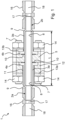
- the insulating screw connection 1 has a first pipe connection 2a with a first pipe section 3a and a first connection collar 4a at its end.
- the first connection collar 4a protrudes radially from the pipe of the first pipe connection 2a and is designed as a circumferential disc.
- a second pipe connection 2b with a second connection collar 4b is provided.
- the two pipe connections 2a, 2b are aligned with their connection collars 4a, 4b in such a way that the mutually facing connection surfaces accommodate an intermediate insulating ring 5 and are pressed together with the insulating ring 5 in a force-fitting manner.
- An electrically insulating, gas-tight inner tube 8 is accommodated in the first and second pipe connections 2a, 2b, which extends at least partially through the connection collars 4a, 4b.
- the front ends of the inner tube 8 rest against end walls 9 in the interior of the pipe connections 2a, 2b, so that the inner tube 8 can be clamped in a force-fitting manner in the two interconnected pipe connections 2a, 2b.
- the inner tube 8 is surrounded in the region of the connecting surfaces of the first and second connecting collars 4a, 4b by a corrugated ring seal 10 inserted into a groove of the connecting collars 4a, 4b.
- the corrugated ring seals 10 are arranged between a respective connecting collar 4a, 4b and the intermediate insulating ring 5 to provide a gas-tight seal in the force shunt.
- the first pipe section 3a carries on its outer circumference a jacket 11 made of insulating material, which provides additional electrical insulation, in particular as protection against leakage currents and external flashover.
- An outer insulating ring 12 circumferentially surrounds a portion of the first pipe section 3a on the outside of the casing 11.
- the outer insulating ring 12 rests against the outside of the first connecting collar 4a, which faces away from the second connecting collar 4b, and circumferentially surrounds the first connecting collar 4a.
- the radially outer region of the outer insulating ring 12 rests against the intermediate insulating ring 5, where they are clamped together in the main force connection.
- a first pressure ring 13a rests against the contact surface of the outer insulating ring 12 opposite the first connection collar 4a.
- a second pressure ring 13b rests against the outside of the second connection collar 4b and the contact surface of the intermediate insulating ring 5 arranged radially above it.
- the two pressure rings 13a, 13b as well as the outer insulating ring 12 and the intermediate insulating ring 5 have aligned bores 6 through which a fastening element 7 in the form of a threaded bolt is inserted.
- the two pressure rings 13a, 13b are pulled towards each other by nuts 14 on the opposite end regions of the fastening elements 7, possibly with additional washers in between, in order to clamp the insulating rings 5, 12 against each other in a force-fitting manner in the final state.
- the connecting collars 4a, 4b are indirectly clamped together in a force shunt.
- the effective length L of the installed insulating screw connection is adjoined by connecting ends of the first and second pipe sections 3a, 3b, which are installed in a pipe screw connection 16.
- the pipe screw connections 16 each have a transition area 17 and, in the direction of extension, ie in the direction of flow, on both sides adjoining Pipe receiving areas 18.
- the diameter of the pipe receiving areas 18 corresponds to the outer diameter of the pipe sections 3a, 3b and is larger than the inner diameter of the pipe section in the transition area 17. This provides a stop with a receiving limit for the inserted pipe sections.
- the pipe fitting 16 can have a polygonal contour on its outer surface to screw the pipe fitting 16 into the pipe sections.
- the pipe receiving areas 18 can have internal threads.
- at least one pipe section can be press-fitted into the associated pipe receiving area 18.
- the pipe fitting 16 can also be soldered or welded to at least one of the pipe sections.
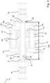
- Figure 2 shows a perspective sectional view of the insulating screw connection 1 from Figure 1 .
- the inner tube 8 extends between the end walls 9 in the enlarged diameter portion of the first and second pipe sections 3a, 3b.
- the inner tube 8 can have conically tapered ends, each with an inclined surface corresponding to the bevel of the end walls 9.
- the insulating rings 5, 12, i.e. the insulating pieces, can be made of an insulating material with acceptance test certificate APZ 3.1 according to EN 10204.
- the thrust rings 13a, 13b, fastening elements 7, and nuts 14 can be made of stainless steel.
- the corrugated ring seals 10 can advantageously have a graphite coating on both sides.
- the insulating jackets 11, 19 can preferably be made of high-strength insulation, for example, polyolefins. They preferably have a layer thickness of at least 2.0 mm.
Landscapes
- Engineering & Computer Science (AREA)
- General Engineering & Computer Science (AREA)
- Mechanical Engineering (AREA)
- Installation Of Bus-Bars (AREA)
- Flanged Joints, Insulating Joints, And Other Joints (AREA)
Applications Claiming Priority (1)
| Application Number | Priority Date | Filing Date | Title |
|---|---|---|---|
| DE102023136595.9A DE102023136595A1 (de) | 2023-12-22 | 2023-12-22 | Gasdichte Isolierverschraubung für eine Rohrleitung |
Publications (2)
| Publication Number | Publication Date |
|---|---|
| EP4575293A2 true EP4575293A2 (fr) | 2025-06-25 |
| EP4575293A3 EP4575293A3 (fr) | 2025-07-02 |
Family
ID=93926573
Family Applications (1)
| Application Number | Title | Priority Date | Filing Date |
|---|---|---|---|
| EP24221098.7A Pending EP4575293A3 (fr) | 2023-12-22 | 2024-12-18 | Raccord fileté isolant étanche aux gaz pour conduite tubulaire |
Country Status (2)
| Country | Link |
|---|---|
| EP (1) | EP4575293A3 (fr) |
| DE (1) | DE102023136595A1 (fr) |
Citations (2)
| Publication number | Priority date | Publication date | Assignee | Title |
|---|---|---|---|---|
| US1783410A (en) | 1928-10-02 | 1930-12-02 | Int Motor Co | Shock insulated union and pipe strap |
| DE60011538T2 (de) | 1999-10-07 | 2005-08-25 | Zoboli, Valter, Formigine | Dielektrische Rohrverbindung, insbesondere für unterirdische Rohrleitungen |
Family Cites Families (3)
| Publication number | Priority date | Publication date | Assignee | Title |
|---|---|---|---|---|
| US1491032A (en) * | 1921-08-12 | 1924-04-22 | Mark V Croker | Insulating coupling |
| FR2987882B1 (fr) * | 2012-03-07 | 2015-04-10 | Airbus Operations Sas | Dispositif de raccordement rigide entre deux canalisations d'un systeme hydraulique de circulation de fluide pour aeronef |
| DE102020128481B4 (de) * | 2020-10-29 | 2022-05-25 | ISOflanges GmbH | Isolierverbinder, Rohrleitungssystem und Verwendung eines Isolierverbinders |
-
2023
- 2023-12-22 DE DE102023136595.9A patent/DE102023136595A1/de active Pending
-
2024
- 2024-12-18 EP EP24221098.7A patent/EP4575293A3/fr active Pending
Patent Citations (2)
| Publication number | Priority date | Publication date | Assignee | Title |
|---|---|---|---|---|
| US1783410A (en) | 1928-10-02 | 1930-12-02 | Int Motor Co | Shock insulated union and pipe strap |
| DE60011538T2 (de) | 1999-10-07 | 2005-08-25 | Zoboli, Valter, Formigine | Dielektrische Rohrverbindung, insbesondere für unterirdische Rohrleitungen |
Also Published As
| Publication number | Publication date |
|---|---|
| EP4575293A3 (fr) | 2025-07-02 |
| DE102023136595A1 (de) | 2025-06-26 |
Similar Documents
| Publication | Publication Date | Title |
|---|---|---|
| DE3933115A1 (de) | Fluessigkeitsdichtes anschlussstueck fuer flexible nichtmetallische leitungen und flexible nichtmetallische rohrleitungen | |
| EP1217286B1 (fr) | Dispositif de raccordement pour deux tubes à double paroi | |
| DE2744674A1 (de) | Flanschverbindung | |
| EP4198371B1 (fr) | Compensateur de pipeline industriel | |
| DE4028237C2 (fr) | ||
| EP0693805B1 (fr) | Elément de raccord pour la connexion électrique et mécanique avec éléments de connexion rotatifs pour gaine de protection de conducteurs électriques | |
| EP4575293A2 (fr) | Raccord fileté isolant étanche aux gaz pour conduite tubulaire | |
| EP3469672B1 (fr) | Isolateur | |
| EP2565898B1 (fr) | Dispositif de commutation électrique | |
| DE1475620A1 (de) | Isolierte Rohrverbindungen | |
| DE60216087T2 (de) | Vorrichtung zum durchführen einer leitung oder dergleichen durch ein bauelement | |
| WO2016050282A1 (fr) | Élément d'électrode | |
| EP2874236B1 (fr) | Dispositif de contact pour la mise en contact d'un blindage de câble | |
| DE102020128481B4 (de) | Isolierverbinder, Rohrleitungssystem und Verwendung eines Isolierverbinders | |
| EP0879377B1 (fr) | Raccord amovible pour tuyaux en plastique | |
| DE10137694C1 (de) | Mauerdurchführung | |
| DE102004013324B4 (de) | Blitzschutz-Potentialausgleich-Anordnung mit einer Verbindungseinrichtung und Verbindungseinrichtung | |
| DE102006024122A1 (de) | Vorrichtung zur Verbindung zweier Sammelrohre bei Kollektoren für Solaranlagen | |
| DE3206311A1 (de) | Belastungsaufnahme-stroemungsmittelleitungsanordnung und anschluss hierfuer | |
| WO2017032573A1 (fr) | Raccord à bride électro-isolant et bague isolante pour raccord à bride | |
| DE102022120822B3 (de) | Rohrverbindungsanordnung mit einem Mantelrohr und Brennkraftmaschine mit einer solchen Rohrverbindungsanordnung | |
| DE1538928B2 (de) | Elektrische isolierende kupplung zweier elektrisch leiten der rohrleitungen zur fuehrung von einem fluessigen kuehl mittel bei einer fluessigkeitsgekuehlten elektrischen ma schine | |
| DE102024100232A1 (de) | Anschlussset für Wärme- und/oder Kälteerzeuger, insbesondere Wärmepumpen, sowie Mehrfachrohrsystem | |
| CH609137A5 (en) | Electrically insulating connection between pipelines carrying water | |
| DE102022128267A1 (de) | Baugruppe zum montieren von messstutzen, system umfassend die baugruppe und verfahren zum montieren der baugruppe |
Legal Events
| Date | Code | Title | Description |
|---|---|---|---|
| PUAI | Public reference made under article 153(3) epc to a published international application that has entered the european phase |
Free format text: ORIGINAL CODE: 0009012 |
|
| STAA | Information on the status of an ep patent application or granted ep patent |
Free format text: STATUS: THE APPLICATION HAS BEEN PUBLISHED |
|
| PUAL | Search report despatched |
Free format text: ORIGINAL CODE: 0009013 |
|
| AK | Designated contracting states |
Kind code of ref document: A2 Designated state(s): AL AT BE BG CH CY CZ DE DK EE ES FI FR GB GR HR HU IE IS IT LI LT LU LV MC ME MK MT NL NO PL PT RO RS SE SI SK SM TR |
|
| AK | Designated contracting states |
Kind code of ref document: A3 Designated state(s): AL AT BE BG CH CY CZ DE DK EE ES FI FR GB GR HR HU IE IS IT LI LT LU LV MC ME MK MT NL NO PL PT RO RS SE SI SK SM TR |
|
| RIC1 | Information provided on ipc code assigned before grant |
Ipc: F16L 25/02 20060101AFI20250527BHEP |
|
| STAA | Information on the status of an ep patent application or granted ep patent |
Free format text: STATUS: REQUEST FOR EXAMINATION WAS MADE |
|
| 17P | Request for examination filed |
Effective date: 20251223 |