EP4575307A2 - Systeme für mehrlinsenvorrichtungen - Google Patents
Systeme für mehrlinsenvorrichtungen Download PDFInfo
- Publication number
- EP4575307A2 EP4575307A2 EP24215098.5A EP24215098A EP4575307A2 EP 4575307 A2 EP4575307 A2 EP 4575307A2 EP 24215098 A EP24215098 A EP 24215098A EP 4575307 A2 EP4575307 A2 EP 4575307A2
- Authority
- EP
- European Patent Office
- Prior art keywords
- lens
- flexible compartment
- gap
- cover
- mount
- Prior art date
- Legal status (The legal status is an assumption and is not a legal conclusion. Google has not performed a legal analysis and makes no representation as to the accuracy of the status listed.)
- Pending
Links
Images


Classifications
-
- F—MECHANICAL ENGINEERING; LIGHTING; HEATING; WEAPONS; BLASTING
- F21—LIGHTING
- F21V—FUNCTIONAL FEATURES OR DETAILS OF LIGHTING DEVICES OR SYSTEMS THEREOF; STRUCTURAL COMBINATIONS OF LIGHTING DEVICES WITH OTHER ARTICLES, NOT OTHERWISE PROVIDED FOR
- F21V31/00—Gas-tight or water-tight arrangements
- F21V31/005—Sealing arrangements therefor
-
- F—MECHANICAL ENGINEERING; LIGHTING; HEATING; WEAPONS; BLASTING
- F21—LIGHTING
- F21V—FUNCTIONAL FEATURES OR DETAILS OF LIGHTING DEVICES OR SYSTEMS THEREOF; STRUCTURAL COMBINATIONS OF LIGHTING DEVICES WITH OTHER ARTICLES, NOT OTHERWISE PROVIDED FOR
- F21V5/00—Refractors for light sources
- F21V5/008—Combination of two or more successive refractors along an optical axis
-
- F—MECHANICAL ENGINEERING; LIGHTING; HEATING; WEAPONS; BLASTING
- F21—LIGHTING
- F21V—FUNCTIONAL FEATURES OR DETAILS OF LIGHTING DEVICES OR SYSTEMS THEREOF; STRUCTURAL COMBINATIONS OF LIGHTING DEVICES WITH OTHER ARTICLES, NOT OTHERWISE PROVIDED FOR
- F21V17/00—Fastening of component parts of lighting devices, e.g. shades, globes, refractors, reflectors, filters, screens, grids or protective cages
- F21V17/10—Fastening of component parts of lighting devices, e.g. shades, globes, refractors, reflectors, filters, screens, grids or protective cages characterised by specific fastening means or way of fastening
-
- B—PERFORMING OPERATIONS; TRANSPORTING
- B01—PHYSICAL OR CHEMICAL PROCESSES OR APPARATUS IN GENERAL
- B01D—SEPARATION
- B01D53/00—Separation of gases or vapours; Recovering vapours of volatile solvents from gases; Chemical or biological purification of waste gases, e.g. engine exhaust gases, smoke, fumes, flue gases, aerosols
- B01D53/26—Drying gases or vapours
-
- F—MECHANICAL ENGINEERING; LIGHTING; HEATING; WEAPONS; BLASTING
- F21—LIGHTING
- F21V—FUNCTIONAL FEATURES OR DETAILS OF LIGHTING DEVICES OR SYSTEMS THEREOF; STRUCTURAL COMBINATIONS OF LIGHTING DEVICES WITH OTHER ARTICLES, NOT OTHERWISE PROVIDED FOR
- F21V31/00—Gas-tight or water-tight arrangements
- F21V31/03—Gas-tight or water-tight arrangements with provision for venting
-
- F—MECHANICAL ENGINEERING; LIGHTING; HEATING; WEAPONS; BLASTING
- F21—LIGHTING
- F21V—FUNCTIONAL FEATURES OR DETAILS OF LIGHTING DEVICES OR SYSTEMS THEREOF; STRUCTURAL COMBINATIONS OF LIGHTING DEVICES WITH OTHER ARTICLES, NOT OTHERWISE PROVIDED FOR
- F21V31/00—Gas-tight or water-tight arrangements
- F21V31/04—Provision of filling media
-
- F—MECHANICAL ENGINEERING; LIGHTING; HEATING; WEAPONS; BLASTING
- F21—LIGHTING
- F21V—FUNCTIONAL FEATURES OR DETAILS OF LIGHTING DEVICES OR SYSTEMS THEREOF; STRUCTURAL COMBINATIONS OF LIGHTING DEVICES WITH OTHER ARTICLES, NOT OTHERWISE PROVIDED FOR
- F21V5/00—Refractors for light sources
- F21V5/04—Refractors for light sources of lens shape
-
- G—PHYSICS
- G02—OPTICS
- G02B—OPTICAL ELEMENTS, SYSTEMS OR APPARATUS
- G02B27/00—Optical systems or apparatus not provided for by any of the groups G02B1/00 - G02B26/00, G02B30/00
- G02B27/0006—Optical systems or apparatus not provided for by any of the groups G02B1/00 - G02B26/00, G02B30/00 with means to keep optical surfaces clean, e.g. by preventing or removing dirt, stains, contamination, condensation
-
- G—PHYSICS
- G02—OPTICS
- G02B—OPTICAL ELEMENTS, SYSTEMS OR APPARATUS
- G02B7/00—Mountings, adjusting means, or light-tight connections, for optical elements
- G02B7/02—Mountings, adjusting means, or light-tight connections, for optical elements for lenses
- G02B7/021—Mountings, adjusting means, or light-tight connections, for optical elements for lenses for more than one lens
-
- G—PHYSICS
- G02—OPTICS
- G02B—OPTICAL ELEMENTS, SYSTEMS OR APPARATUS
- G02B7/00—Mountings, adjusting means, or light-tight connections, for optical elements
- G02B7/02—Mountings, adjusting means, or light-tight connections, for optical elements for lenses
- G02B7/028—Mountings, adjusting means, or light-tight connections, for optical elements for lenses with means for compensating for changes in temperature or for controlling the temperature; thermal stabilisation
-
- F—MECHANICAL ENGINEERING; LIGHTING; HEATING; WEAPONS; BLASTING
- F21—LIGHTING
- F21W—INDEXING SCHEME ASSOCIATED WITH SUBCLASSES F21K, F21L, F21S and F21V, RELATING TO USES OR APPLICATIONS OF LIGHTING DEVICES OR SYSTEMS
- F21W2131/00—Use or application of lighting devices or systems not provided for in codes F21W2102/00-F21W2121/00
- F21W2131/10—Outdoor lighting
- F21W2131/105—Outdoor lighting of arenas or the like
-
- F—MECHANICAL ENGINEERING; LIGHTING; HEATING; WEAPONS; BLASTING
- F21—LIGHTING
- F21W—INDEXING SCHEME ASSOCIATED WITH SUBCLASSES F21K, F21L, F21S and F21V, RELATING TO USES OR APPLICATIONS OF LIGHTING DEVICES OR SYSTEMS
- F21W2131/00—Use or application of lighting devices or systems not provided for in codes F21W2102/00-F21W2121/00
- F21W2131/40—Lighting for industrial, commercial, recreational or military use
- F21W2131/406—Lighting for industrial, commercial, recreational or military use for theatres, stages or film studios
Definitions
- the disclosure relates to multi-lens devices, and more specifically, optical devices.
- Multi-lens devices may include, but are not limited to, windows, cameras, lights, telescopes, and binoculars.
- Multi-lens devices may include a lens assembly having multiple lenses (e.g., two or more lenses) spaced apart from one another.
- the lens assembly may be hermetically sealed.
- a compartment encompassing a gap between adjacent lenses may be hermetically sealed with a gas therein.
- an inert gas may be hermetically sealed between lenses to increase optical clarity of the lens, for instance by reducing condensation.
- Such compartments of the lens assembly may be prone to pressure fluctuations due to variation in ambient temperature. These pressure fluctuations may result in additional stress experienced by gaskets and/or sealants. Over time, the additional stress may degrade the gaskets and/or sealants, allowing the inert gas to escape and/or for impurities to enter. Thus, there may be a demand for systems different than those presently available.
- the disclosure provides support for multi-lens device, comprising a volumetrically flexible compartment fluidly coupled to a gap between a first lens and a second lens of a lens assembly, wherein the gap and the flexible compartment are hermetically sealed from outside of the lens assembly.
- the multi-lens device may include a desiccant positioned between the gap and the flexible compartment. The desiccant may reduce moisture in the gap, decreasing condensation formation within the gap on the lenses.
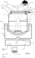
- a plurality of multi-lens devices may be positioned on or coupled to portions of the stage 12.
- the multi-lens device 100 may be exposed to different weather and temperature conditions, such as rain 30, a temperature of the transportation device 20, and outside (e.g., ambient) temperatures. As discussed herein, temperature changes greater than a determined value may stress one or more seals and/or gaskets of the multi-lens device 100.
- Equation (1) may be a simplified representation of general correlations between pressure, temperature, and volume of a sealed compartment of the multi-lens device 100.
- the gas within the sealed compartment may depart from the ideal gas law, behaving more precisely according to other equations of state.
- the correlations between pressure, temperature, and volume e.g., directly related vs inversely related
- equation (1) may be captured by equation (1) and are used herein to demonstrate the effects of ambient condition changes on sealed compartments.
- a expansion device may be included with the multi-lens device 100, where the expansion device is configured to account for pressure changes due to temperature fluctuations, delaying degradation of the seal and/or gasket and thus prolonging a hermetic seal of the hermetically sealed compartments.
- FIG. 2 it shows a perspective view 200 of the multi-lens device 100.
- An axis system 290 comprising an x-axis, a y-axis, and a z-axis is shown in FIGS. 2-5F for comparison of the orientations illustrated therein.
- the x-axis is parallel to a lateral direction
- the y-axis is parallel to a vertical direction
- the z-axis is parallel to a transverse direction.
- the multi-lens device 100 may include a base 124 coupled to a yoke 123.
- the base 124 may be fixed to a structure, such as the stage 12 of FIG. 1 or framework extending therefrom. As such, the base 124 may be stationary.
- the yoke 123 may further be coupled to a housing 110 of the multi-lens device 100.
- the yoke 123 may extend up sides of the multi-lens device 100 and couple to the multi-lens device 100 at diametrically opposite points from one another.
- the housing 110 may be configured to articulate relative to the yoke 123 about a tilt axis 120, parallel to the x-axis.
- the housing 110 may articulate in a rotational direction identical or opposite to arrow 214 about the tilt axis 120.
- the tilt axis 120 may be normal to the pan axis 125.
- An optical path 113 may be adjusted based on the articulation of one or more of the yoke 123 and the housing 110.
- the optical path 113 may be parallel with light emitted from the multi-lens device 100.
- Articulation of the yoke 123 may adjust the horizontal location (e.g., x- and z-directional components) of the optical path 113.
- Articulation of the housing 110 may adjust the vertical elevation (e.g., y-directional component) of the optical path 113.
- the optical path 113 may be fixed, rather than moveable.
- FIGS. 3 and 4 show examples 300 and 400, respectively, of the multi-lens device 100 exposed to a first temperature 302 and a second temperature 402.
- the first temperature 302 is greater than the second temperature 402.
- FIGS. 3 and 4 further illustrate an interior of the multi-lens device 100.
- FIGS. 3 and 4 are described in tandem herein.
- the multi-lens device 100 may include a first articulating joint 310 arranged between the housing 110 and the yoke 123.
- the first articulating joint 310 may allow the housing 110 to rotate about the tilt axis 120 relative to the yoke 123.
- the multi-lens device 100 may further include a second articulating joint 320 arranged between the yoke 123 and the base 124.
- the second articulating joint 320 may allow the yoke 123 to rotate about the pan axis 125 relative to the base 124.
- a controller 126 may be electrically coupled to the multi-lens device 100.
- the controller 126 may include instructions stored in memory (e.g., non-volatile memory) that cause the controller 126 to adjust a position of the multi-lens device 100 along the pan axis 125 or along the tilt axis 120.
- the instructions may further cause the controller to adjust an output of a light source 121.
- the multi-lens device 100 may comprise an interior volume 111 shaped via the housing 110.
- the interior volume 111 may include the light source 121 configured to emit light toward a lens assembly 350.
- the light source 121 may be a light emitting diode (LED) configured to emit one or more colors (e.g., wavelengths) of light.
- the lens assembly 350 may include one or more of the first lens 101, the second lens 102, and a lens assembly housing 103.
- the lens assembly 350 may include two or more lenses, additionally or alternatively to the first lens 101 and the second lens 102.
- the lens assembly housing 103 may be physically coupled to the housing 110.
- the lens assembly housing 103 and the housing 110 may be a single piece.
- the lens assembly 350 may further include a gap 104.
- the gap 104 may be an enclosed space between the first lens 101 and the second lens 102. In this way, the first lens 101 is spaced away from and does not touch the second lens 102.
- the lenses 101, 102 may be constructed of a transparent material, such as glass or plastic.
- the lenses 101, 102 may include surface features, such as bends (e.g., convex or concave surfaces), divots, grooves, protrusions, textures, a combination thereof, and/or the like.
- the surface features may be configured to focus or otherwise redistribute light passing through the lenses 101, 102.
- the lenses 101, 102 may be flat (e.g., planar) on one or more surfaces thereof, such as a window pane. Additionally or alternatively, the lenses 101, 102 may have smooth surfaces.
- the first lens 101 and the second lens 102 may be identical. In other examples, the first lens 101 and the second lens 102 may have different shapes (e.g., convexity, perimeter shape, etc.) and/or sizes (e.g., diameter, perimeter, surface area, thickness, etc.).
- the first lens 101 and the second lens 102 may be positioned such that the lenses 101, 102 receive light emitted from the light source 121.
- the lenses 101, 102 may be positioned such that the second lens 102 is closer to the light source 121 than the first lens 101.
- the light may travel through the first lens 101 prior to reaching the second lens 102.
- the first lens 101 and the second lens 102 may be positioned parallel to one another.
- the optical path 113 may extend through both the first lens 101 and the second lens 102.
- Two or more lenses may be arranged in parallel with gaps similar to the gap 104 interposed between each pair of adjacent lenses. The gaps may be fluidly coupled to each other and hermetically sealed from outside of the multi-lens device 100.
- the optical path 113 may further extend through components interposed between the light source 121 and the lenses 101, 102.
- the optical path 113 may extend through an opening 130 which may adjust a beam width 308 of the light emitted by the light source 121.
- the gap 104 may contain an inert gas.
- the gap 104 may be filled with an inert gas, comprising a single inert gas or a combination of inert gasses.
- the gases included in the gap 104 may include one or more of oxygen, nitrogen, argon, neon, or other inert gas.
- the gap 104 is argon flush such that substantially only argon is present in the gap 104.
- the gap 104 may be sealed from the exterior of the multi-lens device 100.
- one or more seals and/or gaskets may be configured to form a hermetic seal from the atmosphere. In this way, impurities may be blocked from entering the gap 104.
- liquid droplets or vapor may not be allowed within the gap 104.
- condensation forming on one or both of the lenses 101, 102 may be reduced (e.g., prevented), increasing quality of optics of the multi-lens device 100.
- a pressure within the gap 104 may change accordingly. For example, changes in ambient temperature (e.g., due to weather patterns) and/or internal temperature (e.g., the light source 121 heating the gas within the gap 104) may cause such pressure variations, for instance according to the equation (1) provided above or a different corresponding equation of state.
- the lens assembly 350 may further include an expansion device 306 coupled to the lens assembly housing 103.
- the expansion device 306 may include a flexible compartment 105 and a desiccant 106.
- An interior volume of the flexible compartment 105 may be fluidly coupled to the gap 104 via an opening 107 within the lens assembly housing 103.
- the flexible compartment 105 may be sealed from atmosphere such that the gap 104 and interior volume 111 of the housing 110 are hermetically sealed from the atmosphere.
- a sealed space 352 may include the interior of the flexible compartment 105 and the gap 104.
- the sealed space 352 may be sealed from an outside of the lens assembly 350.
- the sealed space 352 may have an adjustable volume, due to inclusion of the flexible compartment 105. In this way, temperature and/or pressure change of gasses in the sealed space 352 may result in a corresponding volume change of the sealed space 352.
- the desiccant 106 may be positioned within or adjacent to the opening 107.
- the desiccant 106 may be configured to reduce moisture within the gap 104.
- the desiccant 106 may include desiccating pellets which draw water molecules from the gap 104 into the flexible compartment 105 while allowing air flow both ways across the desiccant 106.
- the desiccant 106 may include a permeable membrane which allows for air or inert gas flow from the gap 104 to the flexible compartment 105 and vice versa, and lets water molecules pass from the gap 104 to the flexible compartment 105 but not from the flexible compartment 105 to the gap 104.
- water molecules may be drawn out of the gap 104 via the desiccant 106, reducing condensation accumulation on the lenses 101, 102. Additionally, the desiccant 106 may not impede transfer of gasses between the gap 104 and the flexible compartment 105 according to temperatures and pressures.
- the flexible compartment 105 may be configured to expand or contract based on a temperature of gases within the gap 104. That is, the flexible compartment 105 may have an adjustable volume contained therein. Thus, the flexible compartment 105 may also be referred to herein as a volumetrically flexible compartment 105.
- the flexible compartment 105 may be constructed of a flexible material, such as a rubber, silicone, ethylene-propylene diene monomer (EPDM), a combination thereof, or the like.
- the flexible material may form an inflatable balloon.
- the flexible compartment 105 may be structured (e.g., shaped) so as to be collapsible and expandable, with or without stretching the material.
- the flexible compartment 105 may be configured as a bellows with accordion-like folds (e.g., zig zag folds, fan folds, etc.), or other flexible structure that may be concertinaed.
- the flexible compartment 105 may be configured as a moveable piston that shifts to increase or decrease volume fluidly coupled with the gap 104 according to the pressure within the gap 104. In this way, the flexible compartment 105 may allow for adjustment of volume (e.g., rather than pressure) of the gap 104 as a consequence of temperature changes.
- the flexible compartment 105 may be configured to volumetrically expand to at least a quarter of the volume of the gap 104. Additionally or alternatively, the flexible compartment 105 may increase the volume of the sealed space 352 in the expanded position by 1.1 or more times compared to the contracted position.
- the first temperature 302 is a relatively high temperature, which may increase a pressure of gases within the gap 104.
- the flexible compartment 105 is illustrated in an expanded position, thereby increasing a volume of the sealed space 352, and reducing a pressure of the gases therein.
- the flexible compartment 105 is constructed of a flexible material
- the flexible material may be under elastic tension in the expanded position. The elastic tension may cause the flexible compartment to expand further from the gap 104, such as in a direction indicated by arrow 304.
- the flexible compartment 105 includes folds (e.g., a bellows)
- the folds may be stretched to include wider angles therebetween and/or extend further from the gap 104 (e.g., in the direction indicated by the arrow 304) in the expanded position.
- the moveable piston may be positioned further away from the gap 104 (e.g., in the direction indicated by the arrow 304) in the expanded position.
- the second temperature 402 is a relatively low temperature, which may decrease a pressure of gases within the gap 104.
- the flexible compartment 105 is illustrated in a contracted position, thereby decreasing the volume of the sealed space 352, and increasing a pressure of the gases therein.
- the flexible compartment 105 may be compressed towards the gap 104 in the contracted position, for example in a direction indicated by arrow 404.
- the elastic tension may be released, allowing for retraction and bending of the flexible compartment 105.
- the folds may be compacted to include narrower angles therebetween and/or move closer to the gap 104 (e.g., towards the direction indicated by the arrow 404).
- the moveable piston may be located closer to the gap 104 in the contracted position compared to the expanded position.
- the hermetic seal of the gap 104 and the flexible compartment 105 from the exterior of the lens assembly 350 may be maintained such that condensate and other contaminants may not enter the gap 104 and degrade a condition of the first lens 101 or the second lens 102.
- the flexible compartment 105 is shown expanding and contracting in directions parallel with the lenses 101, 102 and perpendicular to the optical path 113.
- the flexible compartment 105 may be oriented to expand and contract in other directions.
- the flexible compartment may extend perpendicular with the lenses 101, 102 and/or parallel with the optical path 113.
- Such a configuration may allow the expansion device 306 to be positioned within the housing 110, as shown in the example of FIGS. 5A-5F , reducing a packing volume of the multi-lens device 100.
- the expansion device 306 may be configured in other orientations, for instance where the flexible compartment extends neither parallel nor perpendicular to the lenses 101, 103 or the optical path 113. In this way, the expansion device 306 may be configured relative to the gap 104 and the lenses 101, 102 according to a configuration of the multi-lens device 100, which may vary between embodiments thereof such as an optical device (e.g., light fixture, binoculars, etc.), automotive device, thermal window, electronic device, etc.
- an optical device e.g., light fixture, binoculars, etc.
- automotive device e.g., thermal window, electronic device, etc.
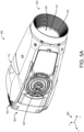
- FIGS. 5A-5E show various views of parts of the multi-lens device 100 and the lens assembly 350 comprising an expansion device 510.
- FIG. 5A shows a fully assembled view 500 of the housing 110 of the multi-lens device 100.
- the interior volume of the housing 110 is sealed and a removable top cover 508 is fastened in place.
- the lens assembly housing 103 may be coupled to the housing 110.
- the lens assembly housing 103 may be integral with the housing 110.
- the lens assembly housing 103 may be at a first end 502 of the multi-lens device 100.
- the housing 110 may include various features for actuating the multi-lens device 100, such as a receptacle 528 for the first articulating joint 310 of FIGS. 3 and 4 .
- FIG. 5B shows an interior view 520 of the housing 110 of the multi-lens device 100.
- the top cover 508 is removed and components of the multi-lens device 100 are shown, including the second lens 102 and the expansion device 510.
- a light source such as the light source 121 of FIGS. 3 and 4 may be positioned near a second end 504 of the multi-lens device 100 within an interior thereof, for instances where the multi-lens device 100 is an optical device such as a light fixture.
- the expansion device 510 is an example of the expansion device 306 of FIGS. 3 and 4 . As such, the expansion device 510 comprises the flexible compartment 105.
- FIG. 5D shows an exploded view 560 of the expansion device 510.
- the lens assembly housing 103 comprises the at least one opening 107 that fluidly couples the flexible compartment 105 to the gap 104 between the first lens 101 and the second lens 102.
- the opening 107 may be used to flush the gap 104 with an inert gas, such as argon, krypton, or nitrogen, prior to installing and sealing the lens assembly housing 103 with the expansion device 510.
- the gap 104 may be filled with an inert gas, and may not contain other materials, such as water vapor.
Landscapes
- Physics & Mathematics (AREA)
- Engineering & Computer Science (AREA)
- General Engineering & Computer Science (AREA)
- General Physics & Mathematics (AREA)
- Optics & Photonics (AREA)
- Chemical & Material Sciences (AREA)
- Analytical Chemistry (AREA)
- General Chemical & Material Sciences (AREA)
- Oil, Petroleum & Natural Gas (AREA)
- Chemical Kinetics & Catalysis (AREA)
- Lens Barrels (AREA)
Applications Claiming Priority (1)
| Application Number | Priority Date | Filing Date | Title |
|---|---|---|---|
| US202363603569P | 2023-11-28 | 2023-11-28 |
Publications (2)
| Publication Number | Publication Date |
|---|---|
| EP4575307A2 true EP4575307A2 (de) | 2025-06-25 |
| EP4575307A3 EP4575307A3 (de) | 2025-08-20 |
Family
ID=93651493
Family Applications (1)
| Application Number | Title | Priority Date | Filing Date |
|---|---|---|---|
| EP24215098.5A Pending EP4575307A3 (de) | 2023-11-28 | 2024-11-25 | Systeme für mehrlinsenvorrichtungen |
Country Status (3)
| Country | Link |
|---|---|
| US (1) | US12449118B2 (de) |
| EP (1) | EP4575307A3 (de) |
| CN (1) | CN120062586A (de) |
Family Cites Families (15)
| Publication number | Priority date | Publication date | Assignee | Title |
|---|---|---|---|---|
| US1325936A (en) * | 1919-04-16 | 1919-12-23 | Soc Optique Mec Haute Prec | Apparatus for rendering the true or apparent focal length of objectives independent of changes of temperature. |
| JP4235427B2 (ja) * | 2002-09-24 | 2009-03-11 | オスラム・メルコ株式会社 | 発光ダイオードランプ |
| JP4497817B2 (ja) * | 2003-01-28 | 2010-07-07 | キヤノン株式会社 | 鏡筒機構およびカメラ |
| JP5022914B2 (ja) * | 2005-01-26 | 2012-09-12 | カール・ツァイス・エスエムティー・ゲーエムベーハー | 光学アセンブリ |
| US7560148B2 (en) * | 2005-04-08 | 2009-07-14 | B-K Lighting, Inc. | Lens assembly apparatus and method |
| US7986472B2 (en) * | 2005-05-31 | 2011-07-26 | Carl Zeiss SMT, AG. | Optical element module |
| IT1391544B1 (it) * | 2008-11-06 | 2012-01-11 | Mantinger | Dispositivo di illuminazione a led (light emitting diode = diodo emettitore di luce), in particolare per gallerie. |
| DE102010001551A1 (de) * | 2010-02-03 | 2011-08-04 | TRUMPF Laser- und Systemtechnik GmbH, 71254 | Adaptive Linse |
| US9465187B2 (en) * | 2010-11-15 | 2016-10-11 | DigitalOptics Corporation MEMS | Thermal despace compensation systems and methods |
| CA2876646C (en) * | 2012-06-13 | 2017-09-05 | Adb Airfield Solutions | Led papi with condensation protection |
| US10247938B2 (en) * | 2014-05-12 | 2019-04-02 | Flextronics Automotive, Inc. | Passive reduction or elimination of frost and fog with expandable air container |
| CN212480961U (zh) * | 2020-07-03 | 2021-02-05 | 宁波东可照明电器有限公司 | 一种防水蒸汽的卫浴灯 |
| DE202021104035U1 (de) * | 2021-07-28 | 2021-08-04 | Trumpf Werkzeugmaschinen Gmbh + Co. Kg | Halteanordnung für ein optisches Element einer Laserbearbeitungsanlage |
| CN116413879B (zh) * | 2021-12-31 | 2025-09-26 | 江西联创电子有限公司 | 光学成像系统及其的组装方法及光学设计补偿方法 |
| CN219389660U (zh) * | 2023-04-18 | 2023-07-21 | 晋江南星海水产食品有限公司 | 一种冷库照明灯 |
-
2024
- 2024-11-25 EP EP24215098.5A patent/EP4575307A3/de active Pending
- 2024-11-27 CN CN202411715352.5A patent/CN120062586A/zh active Pending
- 2024-11-27 US US18/963,416 patent/US12449118B2/en active Active
Also Published As
| Publication number | Publication date |
|---|---|
| US12449118B2 (en) | 2025-10-21 |
| EP4575307A3 (de) | 2025-08-20 |
| CN120062586A (zh) | 2025-05-30 |
| US20250172284A1 (en) | 2025-05-29 |
Similar Documents
| Publication | Publication Date | Title |
|---|---|---|
| KR20060134819A (ko) | 가변 초점 렌즈와 그 제조 방법 | |
| US5611612A (en) | Vehicular lamp having waterproof cover | |
| US5934786A (en) | Sealed lighting unit for clean-rooms and the like | |
| KR20190039267A (ko) | 체크 밸브 | |
| US12449118B2 (en) | Systems for multi-lens devices | |
| US6573487B2 (en) | Image sensor used for image inputting device | |
| AU2010206084A1 (en) | Pressure equalizing equipment housing | |
| US3498695A (en) | Pressure compensated optical device | |
| US20150013814A1 (en) | Sealed fill cap assembly | |
| JP6437573B2 (ja) | 拡張可能なリザーバによる霜及び曇りの受動式低減または解消 | |
| JP5748308B2 (ja) | 圧力平衡用変形範囲を持つハウジング及びハウジング内の密封素子の配置 | |
| US10317782B2 (en) | Laser light source and laser projection display device | |
| US20210033274A1 (en) | A lighting device comprising a housing and a bag | |
| KR20190044998A (ko) | 광학계 렌즈 모듈 | |
| JPH09245507A (ja) | 空気圧維持装置およびそれを用いた灯具 | |
| CN1690755A (zh) | 投射透镜装置 | |
| US20060231361A1 (en) | Single-cylinder hydraulic shock absorber | |
| CN114450612B (zh) | 具有柔顺元件的透镜保持器环 | |
| GB2466966A (en) | Electrical housing including a pressure equalizing device | |
| JP2022025042A (ja) | 車両用灯具の防曇制御システム及び車両用灯具の防曇制御方法 | |
| US20060207847A1 (en) | Single-cylinder hydraulic shock absorber | |
| US20210254814A1 (en) | Light mounting system | |
| CN1824967A (zh) | 单缸液压减振器 | |
| CN216431663U (zh) | 防水防潮低热量照明灯 | |
| JPH0448624Y2 (de) |
Legal Events
| Date | Code | Title | Description |
|---|---|---|---|
| PUAI | Public reference made under article 153(3) epc to a published international application that has entered the european phase |
Free format text: ORIGINAL CODE: 0009012 |
|
| STAA | Information on the status of an ep patent application or granted ep patent |
Free format text: STATUS: THE APPLICATION HAS BEEN PUBLISHED |
|
| AK | Designated contracting states |
Kind code of ref document: A2 Designated state(s): AL AT BE BG CH CY CZ DE DK EE ES FI FR GB GR HR HU IE IS IT LI LT LU LV MC ME MK MT NL NO PL PT RO RS SE SI SK SM TR |
|
| PUAL | Search report despatched |
Free format text: ORIGINAL CODE: 0009013 |
|
| AK | Designated contracting states |
Kind code of ref document: A3 Designated state(s): AL AT BE BG CH CY CZ DE DK EE ES FI FR GB GR HR HU IE IS IT LI LT LU LV MC ME MK MT NL NO PL PT RO RS SE SI SK SM TR |
|
| RIC1 | Information provided on ipc code assigned before grant |
Ipc: F21V 5/00 20180101AFI20250716BHEP Ipc: F21V 31/00 20060101ALI20250716BHEP Ipc: G02B 27/00 20060101ALI20250716BHEP Ipc: G03B 17/08 20210101ALN20250716BHEP |
|
| RAP3 | Party data changed (applicant data changed or rights of an application transferred) |
Owner name: HARMAN PROFESSIONAL DENMARK APS |
|
| STAA | Information on the status of an ep patent application or granted ep patent |
Free format text: STATUS: REQUEST FOR EXAMINATION WAS MADE |
|
| 17P | Request for examination filed |
Effective date: 20260220 |