EP4575349A1 - Wärmequelleneinheit und kühlvorrichtung - Google Patents
Wärmequelleneinheit und kühlvorrichtung Download PDFInfo
- Publication number
- EP4575349A1 EP4575349A1 EP23868072.2A EP23868072A EP4575349A1 EP 4575349 A1 EP4575349 A1 EP 4575349A1 EP 23868072 A EP23868072 A EP 23868072A EP 4575349 A1 EP4575349 A1 EP 4575349A1
- Authority
- EP
- European Patent Office
- Prior art keywords
- refrigerant
- unit
- outdoor
- high pressure
- valve
- Prior art date
- Legal status (The legal status is an assumption and is not a legal conclusion. Google has not performed a legal analysis and makes no representation as to the accuracy of the status listed.)
- Pending
Links
Images






Classifications
-
- F—MECHANICAL ENGINEERING; LIGHTING; HEATING; WEAPONS; BLASTING
- F25—REFRIGERATION OR COOLING; COMBINED HEATING AND REFRIGERATION SYSTEMS; HEAT PUMP SYSTEMS; MANUFACTURE OR STORAGE OF ICE; LIQUEFACTION SOLIDIFICATION OF GASES
- F25B—REFRIGERATION MACHINES, PLANTS OR SYSTEMS; COMBINED HEATING AND REFRIGERATION SYSTEMS; HEAT PUMP SYSTEMS
- F25B13/00—Compression machines, plants or systems, with reversible cycle
-
- F—MECHANICAL ENGINEERING; LIGHTING; HEATING; WEAPONS; BLASTING
- F25—REFRIGERATION OR COOLING; COMBINED HEATING AND REFRIGERATION SYSTEMS; HEAT PUMP SYSTEMS; MANUFACTURE OR STORAGE OF ICE; LIQUEFACTION SOLIDIFICATION OF GASES
- F25B—REFRIGERATION MACHINES, PLANTS OR SYSTEMS; COMBINED HEATING AND REFRIGERATION SYSTEMS; HEAT PUMP SYSTEMS
- F25B41/00—Fluid-circulation arrangements
- F25B41/30—Expansion means; Dispositions thereof
- F25B41/31—Expansion valves
- F25B41/33—Expansion valves with the valve member being actuated by the fluid pressure, e.g. by the pressure of the refrigerant
-
- F—MECHANICAL ENGINEERING; LIGHTING; HEATING; WEAPONS; BLASTING
- F25—REFRIGERATION OR COOLING; COMBINED HEATING AND REFRIGERATION SYSTEMS; HEAT PUMP SYSTEMS; MANUFACTURE OR STORAGE OF ICE; LIQUEFACTION SOLIDIFICATION OF GASES
- F25B—REFRIGERATION MACHINES, PLANTS OR SYSTEMS; COMBINED HEATING AND REFRIGERATION SYSTEMS; HEAT PUMP SYSTEMS
- F25B40/00—Subcoolers, desuperheaters or superheaters
-
- F—MECHANICAL ENGINEERING; LIGHTING; HEATING; WEAPONS; BLASTING
- F25—REFRIGERATION OR COOLING; COMBINED HEATING AND REFRIGERATION SYSTEMS; HEAT PUMP SYSTEMS; MANUFACTURE OR STORAGE OF ICE; LIQUEFACTION SOLIDIFICATION OF GASES
- F25B—REFRIGERATION MACHINES, PLANTS OR SYSTEMS; COMBINED HEATING AND REFRIGERATION SYSTEMS; HEAT PUMP SYSTEMS
- F25B41/00—Fluid-circulation arrangements
- F25B41/20—Disposition of valves, e.g. of on-off valves or flow control valves
-
- F—MECHANICAL ENGINEERING; LIGHTING; HEATING; WEAPONS; BLASTING
- F25—REFRIGERATION OR COOLING; COMBINED HEATING AND REFRIGERATION SYSTEMS; HEAT PUMP SYSTEMS; MANUFACTURE OR STORAGE OF ICE; LIQUEFACTION SOLIDIFICATION OF GASES
- F25B—REFRIGERATION MACHINES, PLANTS OR SYSTEMS; COMBINED HEATING AND REFRIGERATION SYSTEMS; HEAT PUMP SYSTEMS
- F25B41/00—Fluid-circulation arrangements
- F25B41/20—Disposition of valves, e.g. of on-off valves or flow control valves
- F25B41/24—Arrangement of shut-off valves for disconnecting a part of the refrigerant cycle, e.g. an outdoor part
-
- F—MECHANICAL ENGINEERING; LIGHTING; HEATING; WEAPONS; BLASTING
- F25—REFRIGERATION OR COOLING; COMBINED HEATING AND REFRIGERATION SYSTEMS; HEAT PUMP SYSTEMS; MANUFACTURE OR STORAGE OF ICE; LIQUEFACTION SOLIDIFICATION OF GASES
- F25B—REFRIGERATION MACHINES, PLANTS OR SYSTEMS; COMBINED HEATING AND REFRIGERATION SYSTEMS; HEAT PUMP SYSTEMS
- F25B41/00—Fluid-circulation arrangements
- F25B41/30—Expansion means; Dispositions thereof
-
- F—MECHANICAL ENGINEERING; LIGHTING; HEATING; WEAPONS; BLASTING
- F25—REFRIGERATION OR COOLING; COMBINED HEATING AND REFRIGERATION SYSTEMS; HEAT PUMP SYSTEMS; MANUFACTURE OR STORAGE OF ICE; LIQUEFACTION SOLIDIFICATION OF GASES
- F25B—REFRIGERATION MACHINES, PLANTS OR SYSTEMS; COMBINED HEATING AND REFRIGERATION SYSTEMS; HEAT PUMP SYSTEMS
- F25B41/00—Fluid-circulation arrangements
- F25B41/40—Fluid line arrangements
- F25B41/42—Arrangements for diverging or converging flows, e.g. branch lines or junctions
-
- F—MECHANICAL ENGINEERING; LIGHTING; HEATING; WEAPONS; BLASTING
- F25—REFRIGERATION OR COOLING; COMBINED HEATING AND REFRIGERATION SYSTEMS; HEAT PUMP SYSTEMS; MANUFACTURE OR STORAGE OF ICE; LIQUEFACTION SOLIDIFICATION OF GASES
- F25B—REFRIGERATION MACHINES, PLANTS OR SYSTEMS; COMBINED HEATING AND REFRIGERATION SYSTEMS; HEAT PUMP SYSTEMS
- F25B49/00—Arrangement or mounting of control or safety devices
- F25B49/02—Arrangement or mounting of control or safety devices for compression type machines, plants or systems
-
- F—MECHANICAL ENGINEERING; LIGHTING; HEATING; WEAPONS; BLASTING
- F25—REFRIGERATION OR COOLING; COMBINED HEATING AND REFRIGERATION SYSTEMS; HEAT PUMP SYSTEMS; MANUFACTURE OR STORAGE OF ICE; LIQUEFACTION SOLIDIFICATION OF GASES
- F25B—REFRIGERATION MACHINES, PLANTS OR SYSTEMS; COMBINED HEATING AND REFRIGERATION SYSTEMS; HEAT PUMP SYSTEMS
- F25B2313/00—Compression machines, plants or systems with reversible cycle not otherwise provided for
- F25B2313/023—Compression machines, plants or systems with reversible cycle not otherwise provided for using multiple indoor units
- F25B2313/0233—Compression machines, plants or systems with reversible cycle not otherwise provided for using multiple indoor units in parallel arrangements
-
- F—MECHANICAL ENGINEERING; LIGHTING; HEATING; WEAPONS; BLASTING
- F25—REFRIGERATION OR COOLING; COMBINED HEATING AND REFRIGERATION SYSTEMS; HEAT PUMP SYSTEMS; MANUFACTURE OR STORAGE OF ICE; LIQUEFACTION SOLIDIFICATION OF GASES
- F25B—REFRIGERATION MACHINES, PLANTS OR SYSTEMS; COMBINED HEATING AND REFRIGERATION SYSTEMS; HEAT PUMP SYSTEMS
- F25B2313/00—Compression machines, plants or systems with reversible cycle not otherwise provided for
- F25B2313/029—Control issues
- F25B2313/0293—Control issues related to the indoor fan, e.g. controlling speed
-
- F—MECHANICAL ENGINEERING; LIGHTING; HEATING; WEAPONS; BLASTING
- F25—REFRIGERATION OR COOLING; COMBINED HEATING AND REFRIGERATION SYSTEMS; HEAT PUMP SYSTEMS; MANUFACTURE OR STORAGE OF ICE; LIQUEFACTION SOLIDIFICATION OF GASES
- F25B—REFRIGERATION MACHINES, PLANTS OR SYSTEMS; COMBINED HEATING AND REFRIGERATION SYSTEMS; HEAT PUMP SYSTEMS
- F25B2313/00—Compression machines, plants or systems with reversible cycle not otherwise provided for
- F25B2313/029—Control issues
- F25B2313/0294—Control issues related to the outdoor fan, e.g. controlling speed
-
- F—MECHANICAL ENGINEERING; LIGHTING; HEATING; WEAPONS; BLASTING
- F25—REFRIGERATION OR COOLING; COMBINED HEATING AND REFRIGERATION SYSTEMS; HEAT PUMP SYSTEMS; MANUFACTURE OR STORAGE OF ICE; LIQUEFACTION SOLIDIFICATION OF GASES
- F25B—REFRIGERATION MACHINES, PLANTS OR SYSTEMS; COMBINED HEATING AND REFRIGERATION SYSTEMS; HEAT PUMP SYSTEMS
- F25B2400/00—Component parts or details not otherwise provided for in this subclass
- F25B2400/07—Details of compressors or related parts
- F25B2400/072—Intercoolers therefor
-
- F—MECHANICAL ENGINEERING; LIGHTING; HEATING; WEAPONS; BLASTING
- F25—REFRIGERATION OR COOLING; COMBINED HEATING AND REFRIGERATION SYSTEMS; HEAT PUMP SYSTEMS; MANUFACTURE OR STORAGE OF ICE; LIQUEFACTION SOLIDIFICATION OF GASES
- F25B—REFRIGERATION MACHINES, PLANTS OR SYSTEMS; COMBINED HEATING AND REFRIGERATION SYSTEMS; HEAT PUMP SYSTEMS
- F25B2400/00—Component parts or details not otherwise provided for in this subclass
- F25B2400/07—Details of compressors or related parts
- F25B2400/075—Details of compressors or related parts with parallel compressors
-
- F—MECHANICAL ENGINEERING; LIGHTING; HEATING; WEAPONS; BLASTING
- F25—REFRIGERATION OR COOLING; COMBINED HEATING AND REFRIGERATION SYSTEMS; HEAT PUMP SYSTEMS; MANUFACTURE OR STORAGE OF ICE; LIQUEFACTION SOLIDIFICATION OF GASES
- F25B—REFRIGERATION MACHINES, PLANTS OR SYSTEMS; COMBINED HEATING AND REFRIGERATION SYSTEMS; HEAT PUMP SYSTEMS
- F25B2400/00—Component parts or details not otherwise provided for in this subclass
- F25B2400/13—Economisers
-
- F—MECHANICAL ENGINEERING; LIGHTING; HEATING; WEAPONS; BLASTING
- F25—REFRIGERATION OR COOLING; COMBINED HEATING AND REFRIGERATION SYSTEMS; HEAT PUMP SYSTEMS; MANUFACTURE OR STORAGE OF ICE; LIQUEFACTION SOLIDIFICATION OF GASES
- F25B—REFRIGERATION MACHINES, PLANTS OR SYSTEMS; COMBINED HEATING AND REFRIGERATION SYSTEMS; HEAT PUMP SYSTEMS
- F25B2400/00—Component parts or details not otherwise provided for in this subclass
- F25B2400/23—Separators
-
- F—MECHANICAL ENGINEERING; LIGHTING; HEATING; WEAPONS; BLASTING
- F25—REFRIGERATION OR COOLING; COMBINED HEATING AND REFRIGERATION SYSTEMS; HEAT PUMP SYSTEMS; MANUFACTURE OR STORAGE OF ICE; LIQUEFACTION SOLIDIFICATION OF GASES
- F25B—REFRIGERATION MACHINES, PLANTS OR SYSTEMS; COMBINED HEATING AND REFRIGERATION SYSTEMS; HEAT PUMP SYSTEMS
- F25B2600/00—Control issues
- F25B2600/02—Compressor control
- F25B2600/025—Compressor control by controlling speed
- F25B2600/0251—Compressor control by controlling speed with on-off operation
-
- F—MECHANICAL ENGINEERING; LIGHTING; HEATING; WEAPONS; BLASTING
- F25—REFRIGERATION OR COOLING; COMBINED HEATING AND REFRIGERATION SYSTEMS; HEAT PUMP SYSTEMS; MANUFACTURE OR STORAGE OF ICE; LIQUEFACTION SOLIDIFICATION OF GASES
- F25B—REFRIGERATION MACHINES, PLANTS OR SYSTEMS; COMBINED HEATING AND REFRIGERATION SYSTEMS; HEAT PUMP SYSTEMS
- F25B2600/00—Control issues
- F25B2600/25—Control of valves
- F25B2600/2509—Economiser valves
-
- F—MECHANICAL ENGINEERING; LIGHTING; HEATING; WEAPONS; BLASTING
- F25—REFRIGERATION OR COOLING; COMBINED HEATING AND REFRIGERATION SYSTEMS; HEAT PUMP SYSTEMS; MANUFACTURE OR STORAGE OF ICE; LIQUEFACTION SOLIDIFICATION OF GASES
- F25B—REFRIGERATION MACHINES, PLANTS OR SYSTEMS; COMBINED HEATING AND REFRIGERATION SYSTEMS; HEAT PUMP SYSTEMS
- F25B2600/00—Control issues
- F25B2600/25—Control of valves
- F25B2600/2513—Expansion valves
-
- F—MECHANICAL ENGINEERING; LIGHTING; HEATING; WEAPONS; BLASTING
- F25—REFRIGERATION OR COOLING; COMBINED HEATING AND REFRIGERATION SYSTEMS; HEAT PUMP SYSTEMS; MANUFACTURE OR STORAGE OF ICE; LIQUEFACTION SOLIDIFICATION OF GASES
- F25B—REFRIGERATION MACHINES, PLANTS OR SYSTEMS; COMBINED HEATING AND REFRIGERATION SYSTEMS; HEAT PUMP SYSTEMS
- F25B2600/00—Control issues
- F25B2600/25—Control of valves
- F25B2600/2515—Flow valves
-
- F—MECHANICAL ENGINEERING; LIGHTING; HEATING; WEAPONS; BLASTING
- F25—REFRIGERATION OR COOLING; COMBINED HEATING AND REFRIGERATION SYSTEMS; HEAT PUMP SYSTEMS; MANUFACTURE OR STORAGE OF ICE; LIQUEFACTION SOLIDIFICATION OF GASES
- F25B—REFRIGERATION MACHINES, PLANTS OR SYSTEMS; COMBINED HEATING AND REFRIGERATION SYSTEMS; HEAT PUMP SYSTEMS
- F25B2700/00—Sensing or detecting of parameters; Sensors therefor
- F25B2700/19—Pressures
- F25B2700/193—Pressures of the compressor
- F25B2700/1931—Discharge pressures
-
- F—MECHANICAL ENGINEERING; LIGHTING; HEATING; WEAPONS; BLASTING
- F25—REFRIGERATION OR COOLING; COMBINED HEATING AND REFRIGERATION SYSTEMS; HEAT PUMP SYSTEMS; MANUFACTURE OR STORAGE OF ICE; LIQUEFACTION SOLIDIFICATION OF GASES
- F25B—REFRIGERATION MACHINES, PLANTS OR SYSTEMS; COMBINED HEATING AND REFRIGERATION SYSTEMS; HEAT PUMP SYSTEMS
- F25B2700/00—Sensing or detecting of parameters; Sensors therefor
- F25B2700/21—Temperatures
- F25B2700/2115—Temperatures of a compressor or the drive means therefor
- F25B2700/21152—Temperatures of a compressor or the drive means therefor at the discharge side of the compressor
Definitions
- the present disclosure relates to a heat source unit and a refrigeration apparatus.
- Patent Document 1 discloses a refrigeration apparatus including a heat source unit. This refrigeration apparatus performs a refrigeration cycle by circulating a refrigerant between the heat source unit and the utilization-side unit. In the refrigeration cycle performed by this refrigeration apparatus, the high pressure may be higher than the critical pressure of the refrigerant.
- Patent Document 1 Japanese Unexamined Patent Publication No. 2021-32512
- a heat source unit of a refrigeration apparatus performs a protection operation for avoiding damage to the refrigeration apparatus.
- the protection operation include an operation of reducing the rotational speed of the compressor and an operation of stopping the compressor.
- the upper limit pressure is set to a value somewhat lower than the design pressure of the heat source unit. This is because, in the heat source unit, the high pressure of the refrigeration cycle might be considerably changed when the state of the constituent device (e.g., the opening degree of the expansion valve) is changed, and even in this case, the high pressure of the refrigeration cycle is required to be less than the design pressure.
- FIG. 16 is a Mollier diagram (pressure-enthalpy diagram) showing a refrigeration cycle where carbon dioxide is used as a refrigerant.
- the refrigeration cycle indicated by point A, point B1, point C1, and point D1 is a single-stage compression refrigeration cycle where the high pressure is 8 MPa.
- the refrigeration cycle indicated by point A, point B2, point C2, and point D2 is a single-stage compression refrigeration cycle where the high pressure is 10 MPa.
- point C1 indicates the state of the refrigerant where the high pressure of the refrigeration cycle is 8 MPa, and the temperature of the refrigerant at the outlet of the radiator is 40°C.
- point C2 indicates the state of the refrigerant where the high pressure of the refrigeration cycle is 10 MPa, and the temperature of the refrigerant at the outlet of the radiator is 40°C.
- the specific enthalpy of the refrigerant at the outlet of the radiator decreases as the high pressure of the refrigeration cycle increases.
- the cooling capacity of the refrigeration apparatus increases as the high pressure of the refrigeration cycle increases.
- a conventional heat source unit is only able to increase the high pressure of the refrigeration cycle to the upper limit pressure because the difference between the design pressure and the upper limit pressure is relatively large.
- the cooling capacity in the operating state in which the high pressure of the refrigeration cycle is higher than the critical pressure of the refrigerant is low.
- An object of the present disclosure is to provide a heat source unit constituting a refrigeration apparatus, where the cooling capacity in the operating state in which the high pressure of the refrigeration cycle is higher than the critical pressure of the refrigerant is enhanced.
- a first aspect of the present disclosure is directed to a heat source unit (10) connected to a utilization-side unit (60, 70) and configured to perform a refrigeration cycle by circulating a refrigerant between the heat source unit (10) and the utilization-side unit (60, 70), the heat source unit (10) comprising: a compressor (23); a heat-source-side heat exchanger (24); a refrigerant control valve (150) of which an opening degree is variable to control a flow of the refrigerant, where if the opening degree is changed, a high pressure of the refrigeration cycle changes; and a controller (131) configured to change the opening degree of the refrigerant control valve (150) in a stepwise manner, wherein an amount of change by one step in the opening degree of the refrigerant control valve (150) obtained when the controller (131) controls the refrigerant control valve (150) is a unit change amount, a physical quantity indicating the high pressure of the refrigeration cycle is a high pressure index, a value of the high pressure index indicating that the
- the controller (131) changes "the unit change amount employed when the high pressure index is higher than the reference value" to a value lower than "the unit change amount employed when the high pressure index is lower than the reference value.”
- the amount of change in the high pressure of the refrigeration cycle that is obtained when the opening degree of the refrigerant control valve (150) is changed by one step in a state in which the high pressure index is higher than the reference value is smaller.
- the upper limit value of the high pressure of the refrigeration cycle can be more increased than those according to conventional ways, and the cooling capacity obtained in a state in which the high pressure of the refrigeration cycle is higher than the critical pressure of the refrigerant is increased.
- a second aspect of the present disclosure is an embodiment of the first aspect.
- the refrigerant control valve (150) is a first expansion valve (26) configured to decompress a refrigerant flowing out of the heat-source-side heat exchanger (24) functioning as a radiator.
- the controller (131) of the second aspect changes the unit change amount of the opening degree of the first expansion valve (26) based on the high pressure index.
- a third aspect of the present disclosure is an embodiment of the second aspect.
- the unit change amount by which the opening degree of the refrigerant control valve (150) is decreased is a unit decrease amount
- the controller (131) changes the unit decrease amount employed when the high pressure index is higher than the reference value to a value lower than the unit decrease amount employed when the high pressure index is lower than the reference value.
- the controller (131) of the third aspect changes the unit decrease amount of the first expansion valve (26) serving as the refrigerant control valve (150) based on the high pressure index.
- a fourth aspect of the present disclosure is an embodiment of the third aspect.
- the unit change amount by which the opening degree of the refrigerant control valve (150) is increased is a unit increase amount
- the controller (131) changes the unit increase amount employed when the high pressure index is higher than the reference value to a value lower than the unit increase amount employed when the high pressure index is lower than the reference value.
- the controller (131) of the fourth aspect changes both the unit decrease amount and the unit increase amount of the first expansion valve (26) serving as the refrigerant control valve (150) based on the high pressure index.
- the heat source unit further includes: an injection pipe (43) configured to send part of the refrigerant flowing out of the heat-source-side heat exchanger (24) functioning as a radiator to the compressor (23); and a subcooling heat exchanger (28) configured to exchange heat between the refrigerant flowing out of the heat-source-side heat exchanger (24) functioning as a radiator and the refrigerant flowing through the injection pipe (43), thereby cooling the refrigerant flowing out of the heat-source-side exchanger (24) functioning as a radiator, wherein the refrigerant control valve (150) is a second expansion valve (46) that is disposed upstream of the subcooling heat exchanger (28) in the injection pipe (43) and that is configured to reduce the pressure of the refrigerant flowing through the injection pipe (43).
- the refrigerant control valve (150) is a second expansion valve (46) that is disposed upstream of the subcooling heat exchanger (28) in the injection pipe (43) and that is configured to reduce the pressure of the refrigerant flowing through the injection pipe (
- the controller (131) of the fifth aspect changes the unit change amount of the opening degree of the second expansion valve (46) based on the high pressure index.
- the heat source unit further includes: a first expansion valve (26) configured to decompress a refrigerant flowing out of the heat-source-side heat exchanger (24) functioning as a radiator; a receiver (25) into which a refrigerant having passed through the first expansion valve (26) flows; and a venting pipe (41) configured to send a gas refrigerant in the receiver (25) to the compressor (23), wherein the refrigerant control valve (150) is a third expansion valve (42) provided in the venting pipe (41) and configured to decompress a refrigerant.
- the controller (131) of the sixth aspect changes the unit change amount of the opening degree of the third expansion valve (42) based on the high pressure index.
- the controller (131) of the seventh aspect changes the unit increase amount of the second expansion valve (46) or the third expansion valve (42) as the refrigerant control valve (150) based on the high pressure index.
- an eighth aspect of the present disclosure is an embodiment of the seventh aspect.
- the unit change amount by which the opening degree of the refrigerant control valve (150) is decreased is a unit decrease amount
- the controller (131) changes the unit decrease amount employed when the high pressure index is higher than the reference value to a value lower than the unit decrease amount employed when the high pressure index is lower than the reference value.
- the controller (131) of the eighth aspect changes both the unit decrease amount and the unit increase amount of the second expansion valve (46) or the third expansion valve (42) serving as the refrigerant control valve (150) based on the high pressure index.
- a ninth aspect of the present disclosure is an embodiment of any one of the first to eighth aspects.
- the heat-source-side heat exchanger (24) is a heat exchanger configured to exchange heat between the refrigerant and outdoor air, and the high pressure index is a temperature of outdoor air.
- the controller (131) of the ninth aspect changes the unit change amount obtained when the temperature of outdoor air is higher than the reference value to a value lower than the unit change amount obtained when the temperature of outdoor air is lower than the reference value.
- a tenth aspect of the present disclosure is directed to a refrigeration apparatus (1) including: the heat source unit (10) of any one of the first to ninth aspects; and a utilization-side unit (60, 70) connected to the heat source unit (10) via a pipe.
- the heat source unit (10) and the utilization-side unit (60, 70) constitute the refrigeration apparatus (1).
- a refrigeration apparatus (1) performs cooling of an object to be cooled and air-conditioning of an indoor space in parallel.
- the object to be cooled herein includes air in facilities such as a refrigerator, a freezer, and a show case.
- facilities such as a refrigerator, a freezer, and a show case.
- such facilities are each referred to as a refrigeration facility.
- the refrigeration apparatus (1) includes a heat source unit (10) placed outside, an air-conditioning unit (60) configured to perform air-conditioning of an indoor space, and a refrigeration-facility unit (70) configured to cool inside air.
- FIG. 1 shows a single air-conditioning unit (60).
- the refrigeration apparatus (1) may include two or more air-conditioning units (60) connected to each other in parallel.
- FIG. 1 shows a single refrigeration-facility unit (70).
- the refrigeration apparatus (1) may include two or more refrigeration-facility units (70) connected to each other in parallel.
- the refrigeration apparatus (1) includes four connection pipes (2, 3, 4, 5) for connecting the heat source unit (10), the air-conditioning unit (60), and the refrigeration-facility unit (70).
- the heat source unit (10), the air-conditioning unit (60), and the refrigeration-facility unit (70) are connected by the connection pipes (2, 3, 4, 5), thereby forming a refrigerant circuit (6).
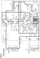
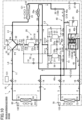
- the heat source unit (10) includes a heat source circuit (11) and an outdoor fan (12).
- the heat source circuit (11) includes a compression unit (20), an outdoor heat exchanger (24), and a receiver (25).
- the heat source circuit (11) includes a first outdoor expansion valve (26) and a second outdoor expansion valve (27).
- the heat source circuit (11) also includes a subcooling heat exchanger (28) and an intercooler (29).
- the first compressor (21) is connected with a first suction pipe (21a) and a first discharge pipe (21b).
- the second compressor (22) is connected with a second suction pipe (22a) and a second discharge pipe (22b).
- the third compressor (23) is connected with a third suction pipe (23a) and a third discharge pipe (23b).
- the heat source circuit (11) includes an intermediate flow path (18).
- the intermediate flow path (18) connects the discharge portions of the first compressor (21) and the second compressor (22) with the suction portion of the third compressor (23).
- the intermediate flow path (18) includes a first discharge pipe (21b), a second discharge pipe (22b), and a third suction pipe (23a).
- the outdoor heat exchanger (24) is an example of a heat-source-side heat exchanger.
- the outdoor heat exchanger (24) is a fin-and-tube air heat exchanger.
- the outdoor fan (12) is disposed near the outdoor heat exchanger (24).
- the outdoor fan (12) transfers outdoor air.
- the outdoor heat exchanger exchanges heat between a refrigerant flowing therethrough and outdoor air transferred from the outdoor fan (12).
- the heat source circuit (11) includes a liquid-side flow path (40).
- the liquid-side flow path (40) is provided between the liquid-side end of the outdoor heat exchanger (24) and the two liquid shut-off valves (14, 16).
- the liquid-side flow path (40) includes first to fifth pipes (40a, 40b, 40c, 40d, 40e).
- One end of the first pipe (40a) is connected to the liquid-side end of the outdoor heat exchanger (24).
- the other end of the first pipe (40a) is connected to the top of the receiver (25).
- One end of the second pipe (40b) is connected to the bottom of the receiver (25).
- the other end of the second pipe (40b) is connected to the second liquid shut-off valve (16).
- One end of the third pipe (40c) is connected to an intermediate portion of the second pipe (40b).
- the other end of the third pipe (40c) is connected to the first liquid shut-off valve (14).
- One end of the fourth pipe (40d) is connected to the first pipe (40a) between the first outdoor expansion valve (26) and the receiver (25).
- the other end of the fourth pipe (40d) is connected to an intermediate portion of the third pipe (40c).
- One end of the fifth pipe (40e) is connected to the first pipe (40a) between the outdoor heat exchanger (24) and the first outdoor expansion valve (26).
- the other end of the fifth pipe (40e) is connected to the second pipe (40b) between the receiver (25) and the junction between the second pipe (40b) and the third pipe (40c).
- the first outdoor expansion valve (26) is provided in the first pipe (40a).
- the first outdoor expansion valve (26) is provided in the first pipe (40a) between the liquid-side end of the outdoor heat exchanger (24) and the junction between the first pipe (40a) and the fourth pipe (40d).
- the first outdoor expansion valve (26) is an example of the first expansion valve.
- the second outdoor expansion valve (27) is provided in the fifth pipe (40e).
- the first outdoor expansion valve (26) and the second outdoor expansion valve (27) are expansion valves of which the opening degrees are adjustable.
- the first outdoor expansion valve (26) and the second outdoor expansion valve (27) are electronic expansion valves each including a valve body and a stepping motor for driving the valve body.
- the stepping motor rotates by an angle corresponding to the number of input pulses.
- the opening degree of each of the first outdoor expansion valve (26) and the second outdoor expansion valve (27) varies by the number of pulses input to the stepping motor.
- the receiver (25) is a hermetically closed container that stores a refrigerant.
- the receiver (25) separates the gas-liquid two-phase state refrigerant into a gas refrigerant and a liquid refrigerant.
- a gas layer and a liquid layer are formed inside the receiver (25).
- the gas layer is formed near the top of the receiver (25).
- the liquid layer is formed near the bottom of the receiver (25).
- the heat source circuit (11) includes a venting pipe (41). One end of the venting pipe (41) is connected to the top of the receiver (25). The other end of the venting pipe (41) is connected to the intermediate flow path (18). The venting pipe (41) sends the gas refrigerant in the receiver (25) to the third compressor (23) through the intermediate flow path (18).
- the venting pipe (41) is provided with a venting valve (42).
- the venting valve (42) is an example of the third expansion valve.
- the venting valve (42) is an electronic expansion valve including a stepping motor. The opening degree of the venting valve (42) varies by the number of pulses input to the stepping motor of the venting valve (42).
- the subcooling heat exchanger (28) includes a first flow path (28a) serving as a high-pressure flow path and a second flow path (28b) serving as a low-pressure flow path.
- the subcooling heat exchanger (28) exchanges heat between the refrigerant in the first flow path (28a) and the refrigerant in the second flow path (28b). In other words, the subcooling heat exchanger (28) cools the refrigerant flowing in the first flow path (28a) by the refrigerant flowing in the second flow path (28b).
- the second flow path (28b) is provided in the middle of the injection flow path (43).
- the injection flow path (43) includes an upstream flow path (44) and a downstream flow path (45).
- the injection flow path (43) is an example of the injection pipe.
- One end of the upstream flow path (44) is connected to a portion of the third pipe (40c) upstream of the junction with the fourth pipe (40d).
- the other end of the upstream flow path (44) is connected to the inflow end of the second flow path (28b).
- the upstream flow path (44) is provided with an injection valve (46).
- the injection valve (46) is an example of the second expansion valve. Similarly to the first outdoor expansion valve (26), the injection valve (46) is an electronic expansion valve including a stepping motor. The opening degree of the injection valve (46) varies by the number of pulses input to the stepping motor of the injection valve (46).
- One end of the downstream flow path (45) is connected to an outflow end of the second flow path (28b).
- the other end of the downstream flow path (45) is connected to the intermediate flow path (18).
- the intercooler (29) is provided in the intermediate flow path (18).
- the intercooler (29) is a fin-and-tube air heat exchanger.
- a cooling fan (29a) is disposed near the intercooler (29). The intercooler (29) exchanges heat between the refrigerant flowing therethrough and the outdoor air transferred from the cooling fan (29a).
- the heat source circuit (11) includes an oil separation circuit.
- the oil separation circuit includes an oil separator (50), a first oil return pipe (51), and a second oil return pipe (52).
- the oil separator (50) is connected to the third discharge pipe (23b).
- the oil separator (50) separates oil from the refrigerant discharged from the compression unit (20).
- Inflow ends of the first oil return pipe (51) and the second oil return pipe (52) communicate with the oil separator (50).
- An outflow end of the first oil return pipe (51) is connected to the intermediate flow path (18).
- the first oil return pipe (51) is provided with a first oil level control valve (53).
- An outflow portion of the second oil return pipe (52) branches into a first branch pipe (52a) and a second branch pipe (52b).
- the first branch pipe (52a) is connected to an oil reservoir of the first compressor (21).
- the second branch pipe (52b) is connected to an oil reservoir of the second compressor (22).
- the first branch pipe (52a) is provided with a second oil level control valve (54).
- the second branch pipe (52b) is provided with a third oil level control valve (55).
- the third check valve (CV3) is provided in the third discharge pipe (23b).
- the fourth check valve (CV4) is provided in the first pipe (40a).
- the fifth check valve (CV5) is provided in the third pipe (40c).
- the sixth check valve (CV6) is provided in the fourth pipe (40d).
- the seventh check valve (CV7) is provided in the fifth pipe (40e).
- the eighth check valve (CV8) is provided in the first bypass pipe (56).
- the ninth check valve (CV9) is provided in the second bypass pipe (57).
- the tenth check valve (CV10) is provided in the third bypass pipe (58).
- the eleventh check valve (CV11) is provided in the first discharge pipe (21b).
- the twelfth check valve (CV12) is provided in the second discharge pipe (22b).
- the indoor heat exchanger (64) is a fin-and-tube air heat exchanger.
- the indoor heat exchanger (64) is an example of a first utilization-side heat exchanger.
- the indoor fan (62) is disposed near the indoor heat exchanger (64).
- the indoor fan (62) transfers indoor air.
- the indoor heat exchanger (64) exchanges heat between the refrigerant flowing therethrough and the indoor air transferred by the indoor fan (62).
- the refrigeration-facility unit (70) is a second utilization unit that cools its internal space.
- the refrigeration-facility unit (70) includes a refrigeration-facility circuit (71) and a refrigeration-facility fan (72).
- the liquid-side end of the refrigeration-facility circuit (71) is connected with the second liquid connection pipe (4).
- the gas-side end of the refrigeration-facility circuit (71) is connected with the second gas connection pipe (5).
- the refrigeration-facility circuit (71) includes a refrigeration-facility expansion valve (73) and a refrigeration-facility heat exchanger (74) in the sequence from the liquid-side end to the gas-side end.
- the refrigeration-facility expansion valve (73) is an expansion valve of which the opening degree is adjustable.
- the refrigeration-facility expansion valve (73) is an electronic expansion valve of which the opening degree is adjusted based on pulse signals.
- the refrigeration-facility heat exchanger (74) is a fin-and-tube air heat exchanger.
- the refrigeration-facility heat exchanger (74) is an example of a second utilization-side heat exchanger.
- the refrigeration-facility fan (72) is disposed near the refrigeration-facility heat exchanger (74).
- the refrigeration-facility fan (72) transfers inside air.
- the refrigeration-facility heat exchanger (74) exchanges heat between the refrigerant flowing therethrough and the inside air transferred by the refrigeration-facility fan (72).
- the suction line (L3), the first gas line (L4), and the second gas line (L5) refer to the flow paths including pipes and elements connected to the pipes.
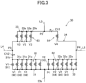
- the first switching flow path (31), the second switching flow path (32), the third switching flow path (33), and the fourth switching flow path (34) are connected in a bridge shape.
- the first switching flow path (31) connects the first port (P1) and the third port (P3).
- the second switching flow path (32) connects the first port (P1) and the fourth port (P4).
- the third switching flow path (33) connects the second port (P2) and the third port (P3).
- the fourth switching flow path (34) connects the second port (P2) and the fourth port (P4).
- the first switching flow path (31) and the second switching flow path (32) are high-pressure flow paths on which high pressure acts.
- the first switching flow path (31) and the second switching flow path (32) are discharge flow paths on which the discharge pressure of the compression unit (20) acts.
- the third switching flow path (33) and the fourth switching flow path (34) are low-pressure flow paths on which low pressure acts.
- the third switching flow path (33) and the fourth switching flow path (34) are suction flow paths on which the suction pressure of the compression unit (20) acts.
- the second opening/closing mechanism (82) includes a plurality of second on-off valves (V2).
- the second switching flow path (32) is provided with two or more second on-off valves (V2) provided in parallel.
- the second switching flow path (32) of this example is provided with seven second on-off valves (V2).
- Each second branch flow path (32a) is provided with one second on-off valve (V2).
- the second on-off valves (V2) include a second switching expansion valve (93) and a second electromagnetic on-off valve (94).
- the number of the second switching expansion valves (93) is one, and the number of the second electromagnetic on-off valves (94) is six.
- the second switching expansion valve (93) is an electronic expansion valve of which the opening degree is variable.
- the third opening/closing mechanism (83) includes a plurality of third on-off valves (V3).
- the second switching flow path (32) is provided with two or more third on-off valves (V3) provided in parallel.
- the third switching flow path (33) of this example is provided with four third on-off valves (V3).
- Each third branch flow path (33a) is provided with one third on-off valve (V3).
- the third on-off valves (V3) are electromagnetic on-off valves.
- the fourth opening/closing mechanism (84) includes one fourth on-off valve (V4).
- the fourth switching flow path (34) is provided with the fourth on-off valve (V4).
- the fourth on-off valve (V4) is an electromagnetic on-off valve.
- the first on-off valve (V1), the second on-off valve (V2), the third on-off valve (V3), and the fourth on-off valve (V4) may be simply referred to as the on-off valve (V) as shown in FIG. 2 .
- the flow path switching mechanism (30) includes check valves (CV1, CV2). Specifically, the fourth switching flow path (34) is provided with the first check valve (CV1). The first switching flow path (31) is provided with the second check valve (CV2).
- the first check valve (CV1) in the fourth switching flow path (34) restricts the flow of a refrigerant from the second port (P2) to the fourth port (P4). More precisely, the first check valve (CV1) in the fourth switching flow path (34) allows the flow of a refrigerant from the fourth port (P4) to the second port (P2) and disallows the flow of a refrigerant from the second port (P2) to the fourth port (P4).
- the first check valve (CV1) in the fourth switching flow path (34) is provided closer to the second port (P2) than the on-off valve (V) is.
- the second check valve (CV2) in the first switching flow path (31) restricts the flow of a refrigerant from the third port (P3) to the first port (P1). More precisely, the second check valve (CV2) in the first switching flow path (31) allows the flow of a refrigerant from the first port (P1) to the third port (P3) and disallows the flow of a refrigerant from the third port (P3) to the first port (P1).
- the second check valve (CV2) is provided in the main flow path (31b) of the first switching flow path (31).
- the main flow path (31b) is a flow path connected with the ends of the first branch flow paths (31a).
- the second check valve (CV2) in the first switching flow path (31) is provided closer to the third port (P3) than the on-off valve (V) is.
- the refrigeration apparatus (1) includes a plurality of sensors.
- the sensors include a refrigerant pressure sensor that detects the pressure of a refrigerant; a refrigerant temperature sensor that detects the temperature of a refrigerant; and an air temperature sensor that detects the temperature of air.
- the refrigerant pressure sensors include a high pressure sensor (101), an intermediate pressure sensor (102), a first suction pressure sensor (103), a second suction pressure sensor (104), and a liquid-side pressure sensor (105).
- the high pressure sensor (101) is provided in the third discharge pipe (23b).
- the high pressure sensor (101) detects the pressure of a refrigerant on the discharge side of the compression unit (20), in other words, detects the high pressure of the refrigerant circuit (6).
- the intermediate pressure sensor (102) is provided in the third suction pipe (23a).
- the intermediate pressure sensor (102) detects the pressure of a refrigerant between the lower-stage compressor and the higher-stage compressor, in other words, detects the intermediate pressure of the refrigerant circuit (6).
- the first suction pressure sensor (103) is provided in the first suction pipe (21a).
- the first suction pressure sensor (103) detects the pressure of a refrigerant on the suction side of the first compressor (21).
- the second suction pressure sensor (104) is provided in the second suction pipe (22a).
- the second suction pressure sensor (104) detects the pressure of a refrigerant on the suction side of the second compressor (22).
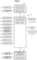
- the outdoor controller (131) of the control system (130) performs protection operation and performs control of the first outdoor expansion valve (26).
- the outdoor controller (131) monitors a measurement value of the high pressure sensor (101).
- the measurement value PH of the high pressure sensor (101) is a high pressure of the refrigeration cycle.
- the outdoor controller (131) performs the protection operation in order to forcibly reduce the operation capacity of the compression unit (20).
- the upper limit pressure is lower than a design pressure of the heat source unit (e.g., 12 MPa).
- the outdoor controller (131) reduces the rotational speed of a compressor in operation among the first compressor (21), the second compressor (22), and the third compressor (23) constituting the compression unit (20) by a predetermined value at the time when it is determined that the measurement value PH of the high pressure sensor (101) is higher than the upper limit pressure. As a result, the operating capacity of the compression unit (20) is reduced. If the operating capacity of the compression unit (20) decreases, the flow rate of the refrigerant discharged from the compression unit (20) decreases, and the high pressure of the refrigeration cycle decreases.
- the outdoor controller (131) controls the first outdoor expansion valve (26).
- the outdoor heat exchanger (24) functions as a radiator. If the opening degree of the first outdoor expansion valve (26) is changed in a state in which the outdoor heat exchanger (24) functions as a radiator, the pressure of the refrigerant in the outdoor heat exchanger (24) changes.
- the pressure of a refrigerant in the outdoor heat exchanger (24) is a high pressure of the refrigeration cycle.
- the first outdoor expansion valve (26) is a refrigerant control valve (150) where if its opening degree is changed, the high pressure of the refrigeration cycle changes.
- the outdoor controller (131) increases or decreases the opening degree of the first outdoor expansion valve (26) in a stepwise manner.
- the amount of change by one step in the opening degree of the first outdoor expansion valve (26) employed when the outdoor controller (131) controls the first outdoor expansion valve (26) is the unit change amount ⁇ EV1.
- the unit change amount ⁇ EV1 employed when the opening degree of the first outdoor expansion valve (26) is increased is the unit increase amount
- the unit change amount ⁇ EV1 employed when the opening degree of the first outdoor expansion valve (26) is decreased is the unit decrease amount.
- the unit increase amount and the unit decrease amount of the opening degree of the first outdoor expansion valve (26) are the same value.
- the outdoor controller (131) adjusts the opening degree of the first outdoor expansion valve (26) based on the pressure of the refrigerant in the receiver (25) (hereinafter referred to as the receiver pressure Pr).
- the outdoor controller (131) changes the unit change amount ⁇ EV1 of the opening degree of the first outdoor expansion valve (26) based on the temperature of outdoor air (the outdoor air temperature To).
- the outdoor air temperature To is a measurement value of the outdoor air temperature sensor (121).
- the cooling capacity of the refrigeration apparatus (1) decreases as the outdoor air temperature To increases.
- the refrigeration apparatus (1) increases the high pressure of the refrigeration cycle by increasing the operating capacity of the compression unit (20). In this manner, as the outdoor air temperature To increases, the high pressure of the refrigeration cycle increases.
- the outdoor air temperature To is a physical quantity indicating the high pressure of the refrigeration cycle (i.e., the high pressure index).
- the operation of the outdoor controller (131) controlling the first outdoor expansion valve (26) will be described with reference to the flowchart of FIG. 11 .
- the outdoor controller (131) repeats the operation shown in FIG. 11 every predetermined time (e.g., every 10 seconds). Note that the specific numerical values shown in this description are mere examples.
- the outdoor controller (131) obtains the measurement value of the outdoor air temperature sensor (121) as the outdoor air temperature To.
- the outdoor controller (131) compares the obtained outdoor air temperature To with a predetermined reference value (38°C in this embodiment). Specifically, the outdoor controller (131) determines whether the condition that the outdoor air temperature To is 38°C or higher is true.
- the reference value (38°C in this embodiment) of the outdoor air temperature To is set to a value higher than the temperature of the critical point (the critical temperature) of a refrigerant in the refrigerant circuit (6) (carbon dioxide in this embodiment).
- step ST12 or step ST13 the outdoor controller (131) conducts the process of step ST14.
- the outdoor controller (131) sets the unit change amount ⁇ EV1 of the first outdoor expansion valve (26).
- ⁇ VO is a reference change amount of the opening degree of the electronic expansion valve.
- ⁇ VO is 100 pulses.
- the outdoor controller (131) of this embodiment sets the unit change amount ⁇ EV1 to 100 pulses if the outdoor air temperature To ⁇ 38°C, and sets the unit change amount ⁇ EV1 to 50 pulses if the outdoor air temperature To ⁇ 38°C.
- the outdoor controller (131) obtains the measurement value of the liquid-side pressure sensor (105) as the receiver pressure Pr.
- the outdoor controller (131) compares the obtained receiver pressure Pr with the lower limit value Pr_t1 of the target range.
- the outdoor controller (131) conducts the process of step ST16 if the condition that the receiver pressure Pr is lower than the lower limit value Pr_t1 (Pr ⁇ Pr_t1) is true, and conducts the process of step ST17 if the condition is not true.
- the outdoor controller (131) increases the opening degree of the first outdoor expansion valve (26) by the unit change amount ⁇ EV1 set in the process of step ST14. If the opening degree of the first outdoor expansion valve (26) increases in a state in which the outdoor heat exchanger (24) functions as a radiator, the pressure of a refrigerant flowing into the receiver (25) increases, and the receiver pressure Pr increases. If the opening degree of the first outdoor expansion valve (26) increases in this state, the pressure of the refrigerant in the outdoor heat exchanger (24) functioning as a radiator decreases, and the high pressure of the refrigeration cycle decreases.
- the outdoor controller (131) compares the obtained receiver pressure Pr with the upper limit value Pr_t2 of the target range.
- the upper limit value Pr_t2 of the target range is a value lower than the critical pressure of the refrigerant. If the condition that the receiver pressure Pr is higher than the upper limit value Pr_t2 (Pr > Pr_t2) is true, the outdoor controller (131) conducts the process of step ST18.
- the outdoor controller (131) decreases the opening degree of the first outdoor expansion valve (26) by the unit change amount ⁇ EV1 set in the process of step ST14. If the opening degree of the first outdoor expansion valve (26) decreases in a state in which the outdoor heat exchanger (24) functions as a radiator, the pressure of the refrigerant flowing into the receiver (25) decreases, and the receiver pressure Pr decreases. If the opening degree of the first outdoor expansion valve (26) decreases in this state, the pressure of the refrigerant in the outdoor heat exchanger (24) functioning as a radiator increases, and the high pressure of the refrigeration cycle increases.
- step ST17 If the condition in the process of step ST17 is not true, the receiver pressure Pr is in the target range. Thus, if this condition is not true, the outdoor controller (131) does not change the opening degree of the first outdoor expansion valve (26), and ends the control operation of the first outdoor expansion valve (26).
- the outdoor controller (131) of this embodiment changes "the unit change amount ⁇ EV1 employed when the outdoor air temperature To as the high pressure index is higher than the reference value" to a value lower than "the unit change amount ⁇ EV1 employed when the high pressure index is lower than the reference value.”
- the upper limit value of the high pressure of the refrigeration cycle (the upper limit pressure) can be more increased than according to conventional ways, and the cooling capacity of the refrigeration apparatus (1) obtained in a state in which the high pressure of the refrigeration cycle is higher than the critical pressure of the refrigerant can be increased.
- the high-pressure of the refrigeration cycle is absolutely required not to exceed the design pressure (e.g., 12 MPa) of the heat source unit (10). This is because the heat source unit (10) is damaged if the high pressure of the refrigeration cycle is higher than the design pressure of the heat source unit (10). Thus, if the high pressure of the refrigeration cycle is higher than a predetermined upper limit pressure when the operation is being performed, the heat source unit (10) performs the protection operation to avoid damage to the heat source unit (10).
- the difference between the design pressure and the upper limit pressure is desirably as small as possible.
- the opening degree of the first outdoor expansion valve (26) is changed by one step in a state in which the high pressure of the refrigeration cycle is slightly lower than the upper limit pressure, the high pressure of the refrigeration cycle might increase and the high pressure of the refrigeration cycle might exceed the design pressure.
- the upper limit pressure is necessarily set to a somewhat lower value (e.g., 10 MPa) than the design pressure (e.g., 12 MPa).
- the unit change amount of the opening degree of the first outdoor expansion valve (26) is set to a relatively small value (e.g., 50 pulses) in any cases.
- a relatively small value e.g. 50 pulses
- the opening degree of the first outdoor expansion valve (26) cannot be changed in accordance with the change in the operation state of the refrigeration apparatus (1), and thus the opening degree of the first outdoor expansion valve (26) might be unable to be controlled appropriately.
- the outdoor controller (131) obtains the measurement value of the outdoor air temperature sensor (121) as the outdoor air temperature To.
- the outdoor controller (131) compares the obtained outdoor air temperature To with a predetermined reference value (38°C in this embodiment). Specifically, the outdoor controller (131) determines whether the condition that the outdoor air temperature To is 38°C or higher is true.
- HT is a coefficient used to determine the unit change amount ⁇ EV2.
- step ST24 the outdoor controller (131) sets the unit change amount ⁇ EV2 of the injection valve (46).
- ⁇ VO is a reference change amount of the opening degree of the electronic expansion valve.
- ⁇ VO is 100 pulses.
- the outdoor controller (131) of this embodiment sets the unit change amount ⁇ EV2 to 100 pulses if the outdoor air temperature To ⁇ 38°C, and sets the unit change amount ⁇ EV2 to 50 pulses if the outdoor air temperature To ⁇ 38°C.
- the outdoor controller (131) compares the calculated degree of subcooling SC with the lower limit value SC_t1 (e.g., 2°C) of the target range.
- the outdoor controller (131) conducts the process of step ST26 if the condition that the degree of subcooling SC is lower than the lower limit value SC_t1 (SC ⁇ SC_t1) is true, and conducts the process of step ST27 if the condition is not true.
- the outdoor controller (131) increases the opening degree of the injection valve (46) by the unit change amount ⁇ EV2 set in the process of step ST24. If the opening degree of the injection valve (46) increases, the flow rate of the refrigerant flowing through the second flow path (28b) of the subcooling heat exchanger (28) increases, and the temperature of the refrigerant at the outlet of the first flow path (28a) of the subcooling heat exchanger (28) decreases. Thus, the degree of subcooling SC increases. If the opening degree of the injection valve (46) increases, the flow rate of the refrigerant flowing into the third compressor (23) through the injection flow path (43) increases, and the high pressure of the refrigeration cycle increases.
- the outdoor controller (131) compares the calculated degree of subcooling SC with the upper limit value SC_t2 (e.g., 4°C) of the target range.
- the outdoor controller (131) conducts the process of step ST28 if the condition that the degree of subcooling SC is higher than the upper limit value SC_t2 (SC > SC_t2) is true, and conducts the process of step ST29 if the condition is not true.
- the outdoor controller (131) increases the opening degree of the injection valve (46) by the unit change amount ⁇ EV2 set in the process of step ST24. If the opening degree of the injection valve (46) decreases, the flow rate of the refrigerant flowing through the second flow path (28b) of the subcooling heat exchanger (28) decreases, and the temperature of the refrigerant at the outlet of the first flow path (28a) of the subcooling heat exchanger (28) increases. Thus, the degree of subcooling SC decreases. If the opening degree of the injection valve (46) decreases, the flow rate of the refrigerant flowing into the third compressor (23) through the injection flow path (43) decreases, and the high pressure of the refrigeration cycle decreases.
- the outdoor controller (131) compares the calculated degree of suction superheat SH with the lower limit value SH_t1 (e.g., 5°C) of the target range.
- the outdoor controller (131) conducts the process of step ST30 if the condition that the degree of suction superheat SH is lower than the lower limit value SH_t1 (SH ⁇ SH_t1) is true, and conducts the process of step ST31 if the condition is not true.
- the outdoor controller (131) decreases the opening degree of the injection valve (46) by the unit change amount ⁇ EV2 set in the process of step ST24. If the opening degree of the injection valve (46) decreases, the flow rate of the refrigerant flowing into the third compressor (23) through the injection flow path (43) decreases, and the temperature of the refrigerant sucked into the third compressor (23) increases. Thus, the degree of suction superheat SH increases.
- the outdoor controller (131) compares the calculated degree of suction superheat SH with the upper limit value SH_t2 (e.g., 10°C) of the target range. If the condition that the degree of suction superheat SH is higher than the upper limit value SH_t2 (SH > SH_t2) is true, the outdoor controller (131) conducts the process of step ST32.
- SH_t2 e.g. 10°C
- the outdoor controller (131) increases the opening degree of the injection valve (46) by the unit change amount ⁇ EV2 set in the process of step ST24. If the opening degree of the injection valve (46) increases, the flow rate of the refrigerant flowing into the third compressor (23) through the injection flow path (43) increases, and the temperature of the refrigerant sucked into the third compressor (23) decreases. Thus, the degree of suction superheat SH decreases.
- step ST31 If the condition in the process of step ST31 is not true, the degree of subcooling SC and the degree of suction superheat SH are in their target ranges. Thus, if this condition is not true, the outdoor controller (131) does not change the opening degree of the injection valve (46), and ends the control operation of the injection valve (46).
- the outdoor controller (131) of this embodiment may be configured to change both the unit change amount ⁇ EV1 of the opening degree of the first outdoor expansion valve (26) and the unit change amount ⁇ EV2 of the opening degree of the injection valve (46) based on the outdoor air temperature To as the high pressure index.
- the outdoor controller (131) of this variation adjusts the opening degree of the first outdoor expansion valve (26) in the same way the outdoor controller (131) of the first embodiment does.
- the outdoor controller (131) of this embodiment may be configured to change only the unit increase amount among the unit increase amount and the unit decrease amount of the opening degree of the injection valve (46) based on the outdoor air temperature To as the high pressure index.
- the outdoor controller (131) of this variation changes "the unit increase amount of the injection valve (46) employed when the outdoor air temperature To as the high pressure index is higher than the reference value" to a value smaller than "the unit increase amount of the injection valve (46) employed when the high pressure index is lower than the reference value.”
- the outdoor controller (131) of this variation keeps the unit decrease amount of the injection valve (46) constant regardless of the outdoor air temperature To as the high pressure index.
- the heat source unit (10) of this embodiment includes a modified version of the outdoor controller (131) of the heat source unit (10) of the first embodiment.
- the outdoor controller (131) of this embodiment is configured to change the unit change amount ⁇ EV3 of the opening degree of the venting valve (42) based on the outdoor air temperature To as the high pressure index.
- the venting pipe (41) is a refrigerant control valve (150) where if its opening degree is changed, the high pressure of the refrigeration cycle changes.
- the outdoor controller (131) of this embodiment increases or decreases the opening degree of the venting valve (42) in a stepwise manner.
- the amount of change by one step in the opening degree of the venting valve (42) employed when the outdoor controller (131) controls the venting valve (42) is the unit change amount ⁇ EV3.
- the unit change amount ⁇ EV3 employed when the opening degree of the venting valve (42) is increased is the unit increase amount
- the unit change amount ⁇ EV3 employed when the opening degree of the venting valve (42) is decreased is the unit decrease amount.
- the unit increase amount and the unit decrease amount of the opening degree of the venting valve (42) are the same value.
- the outdoor controller (131) of this embodiment adjusts the opening degree of the venting valve (42) based on the receiver pressure Pr; the degree of superheat of the refrigerant sucked into the third compressor (23) (the degree of suction superheat SH); and the pressure of the refrigerant sucked into the third compressor (23) (the intermediate pressure Pm).
- the outdoor controller (131) changes the unit change amount ⁇ EV3 of the opening degree of the venting valve (42) based on the temperature of outdoor air (the outdoor air temperature To).
- the operation of the outdoor controller (131) of this embodiment controlling the venting valve (42) will be described with reference to the flowchart of FIG. 13 .
- the outdoor controller (131) repeats the operation shown in FIG. 13 every predetermined time (e.g., every 10 seconds). Note that the specific numerical values shown in this description are mere examples.
- ⁇ VO is a reference change amount of the opening degree of the electronic expansion valve.
- ⁇ VO is 100 pulses.
- the outdoor controller (131) of this embodiment sets the unit change amount ⁇ EV3 to 100 pulses.
- the outdoor controller (131) may set the unit change amount ⁇ EV3 of the venting valve (42) to a value greater than ⁇ VO.
- the outdoor controller (131) obtains the measurement value of the liquid-side pressure sensor (105) as the receiver pressure Pr.
- the outdoor controller (131) compares the obtained receiver pressure Pr with the upper limit value Pr_max of the receiver pressure.
- the outdoor controller (131) conducts the process of step ST43 if the condition that the receiver pressure Pr is equal to or higher than the upper limit value Pr_max (Pr ⁇ Pr_max) is true, and conducts the process of step ST44 if the condition is not true.
- the outdoor controller (131) increases the opening degree of the venting valve (42) by the unit change amount ⁇ EV3 set in the process of step ST41. If the opening degree of the venting valve (42) increases, the flow rate of the gas refrigerant flowing out from the receiver (25) to the venting pipe (41) increases, and the receiver pressure Pr decreases.
- the outdoor controller (131) calculates the degree of superheat of the refrigerant sucked into the third compressors (23) (the degree of suction superheat SH). Similarly to the process of step ST29 in FIG. 12 , the outdoor controller (131) obtains the measurement value of the intermediate pressure sensor (102) and the measurement value of the third suction temperature sensor (116), and calculates the degree of suction superheat SH using these obtained measurement values.
- the outdoor controller (131) compares the calculated degree of suction superheat SH with the lower limit value SH_min (e.g., 0°C) of the degree of suction superheat SH.
- the outdoor controller (131) conducts the process of step ST45 if the condition that the degree of suction superheat SH is equal to or lower than the lower limit value SH_min (SH ⁇ SH_min) is true, and conducts the process of step ST46 if the condition is not true.
- the outdoor controller (131) obtains the measurement value of the outdoor air temperature sensor (121) as the outdoor air temperature To.
- the outdoor controller (131) compares the obtained outdoor air temperature To with a predetermined reference value (38°C in this embodiment). Specifically, the outdoor controller (131) determines whether the condition that the outdoor air temperature To is 38°C or higher is true.
Landscapes
- Engineering & Computer Science (AREA)
- Physics & Mathematics (AREA)
- Mechanical Engineering (AREA)
- Thermal Sciences (AREA)
- General Engineering & Computer Science (AREA)
- Fluid Mechanics (AREA)
- Compression-Type Refrigeration Machines With Reversible Cycles (AREA)
- Air Conditioning Control Device (AREA)
Applications Claiming Priority (2)
| Application Number | Priority Date | Filing Date | Title |
|---|---|---|---|
| JP2022148785A JP7401810B1 (ja) | 2022-09-20 | 2022-09-20 | 熱源ユニットおよび冷凍装置 |
| PCT/JP2023/032846 WO2024062949A1 (ja) | 2022-09-20 | 2023-09-08 | 熱源ユニットおよび冷凍装置 |
Publications (2)
| Publication Number | Publication Date |
|---|---|
| EP4575349A1 true EP4575349A1 (de) | 2025-06-25 |
| EP4575349A4 EP4575349A4 (de) | 2025-12-03 |
Family
ID=89190338
Family Applications (1)
| Application Number | Title | Priority Date | Filing Date |
|---|---|---|---|
| EP23868072.2A Pending EP4575349A4 (de) | 2022-09-20 | 2023-09-08 | Wärmequelleneinheit und kühlvorrichtung |
Country Status (5)
| Country | Link |
|---|---|
| US (1) | US20250207830A1 (de) |
| EP (1) | EP4575349A4 (de) |
| JP (1) | JP7401810B1 (de) |
| CN (1) | CN119895209B (de) |
| WO (1) | WO2024062949A1 (de) |
Family Cites Families (8)
| Publication number | Priority date | Publication date | Assignee | Title |
|---|---|---|---|---|
| WO2009011197A1 (ja) | 2007-07-18 | 2009-01-22 | Mitsubishi Electric Corporation | 冷凍サイクル装置およびその運転制御方法 |
| JP2009097779A (ja) * | 2007-10-16 | 2009-05-07 | Denso Corp | 超臨界冷凍サイクル |
| JP2010101552A (ja) | 2008-10-23 | 2010-05-06 | Sanden Corp | ガスインジェクション冷凍システム |
| JP6380088B2 (ja) | 2014-12-24 | 2018-08-29 | 株式会社デンソー | ヒートポンプサイクルの制御方法、および加熱システム |
| JP7082098B2 (ja) | 2019-08-27 | 2022-06-07 | ダイキン工業株式会社 | 熱源ユニット及び冷凍装置 |
| JP2021055917A (ja) * | 2019-09-30 | 2021-04-08 | ダイキン工業株式会社 | 熱源ユニット及び冷凍装置 |
| JP6904396B2 (ja) | 2019-09-30 | 2021-07-14 | ダイキン工業株式会社 | 熱源ユニット及び冷凍装置 |
| JP7007612B2 (ja) | 2020-06-30 | 2022-01-24 | ダイキン工業株式会社 | 冷凍システムおよび熱源ユニット |
-
2022
- 2022-09-20 JP JP2022148785A patent/JP7401810B1/ja active Active
-
2023
- 2023-09-08 EP EP23868072.2A patent/EP4575349A4/de active Pending
- 2023-09-08 CN CN202380064727.3A patent/CN119895209B/zh active Active
- 2023-09-08 WO PCT/JP2023/032846 patent/WO2024062949A1/ja not_active Ceased
-
2025
- 2025-03-17 US US19/080,942 patent/US20250207830A1/en active Pending
Also Published As
| Publication number | Publication date |
|---|---|
| US20250207830A1 (en) | 2025-06-26 |
| CN119895209B (zh) | 2025-12-02 |
| JP2024043667A (ja) | 2024-04-02 |
| EP4575349A4 (de) | 2025-12-03 |
| JP7401810B1 (ja) | 2023-12-20 |
| WO2024062949A1 (ja) | 2024-03-28 |
| CN119895209A (zh) | 2025-04-25 |
Similar Documents
| Publication | Publication Date | Title |
|---|---|---|
| CN116097049B (zh) | 热源机组及制冷装置 | |
| EP2960596A1 (de) | Klimaanlagenvorrichtung | |
| EP3988869B1 (de) | Kühlvorrichtung | |
| EP3760947B1 (de) | Kühlvorrichtung | |
| EP4015936B1 (de) | Wärmequelleneinheit und kühlvorrichtung | |
| EP4027077B1 (de) | Wärmequelleneinheit und kühlvorrichtung | |
| EP4317854A1 (de) | Wärmequelleneinheit und kühlvorrichtung | |
| EP4303504B1 (de) | Wärmequelleneinheit und kühlvorrichtung | |
| EP1674806A1 (de) | Unterkühlungsvorrichtung | |
| EP4033178B1 (de) | Kühlvorrichtung | |
| EP4015939B1 (de) | Kühlvorrichtung | |
| CN119895209B (zh) | 热源机组及制冷装置 | |
| US20250180245A1 (en) | Air-conditioning apparatus | |
| EP4647682A1 (de) | Klimaanlage | |
| EP4047289A1 (de) | Zwischeneinheit für eine kühlvorrichtung und kühlvorrichtung | |
| JP7617464B1 (ja) | 空気調和装置 | |
| EP4542142A1 (de) | Wärmequelleneinheit und gefriervorrichtung | |
| EP4030124A1 (de) | Kühlvorrichtung und wärmequelleneinheit | |
| EP4628816A1 (de) | Wärmequelleneinheit und kühlvorrichtung | |
| JP2025050551A (ja) | 熱源ユニットおよび冷凍装置 | |
| JP2022083173A (ja) | 熱源システムおよび冷凍装置 | |
| JP2022083089A (ja) | 熱源システムおよび冷凍装置 |
Legal Events
| Date | Code | Title | Description |
|---|---|---|---|
| STAA | Information on the status of an ep patent application or granted ep patent |
Free format text: STATUS: THE INTERNATIONAL PUBLICATION HAS BEEN MADE |
|
| PUAI | Public reference made under article 153(3) epc to a published international application that has entered the european phase |
Free format text: ORIGINAL CODE: 0009012 |
|
| STAA | Information on the status of an ep patent application or granted ep patent |
Free format text: STATUS: REQUEST FOR EXAMINATION WAS MADE |
|
| 17P | Request for examination filed |
Effective date: 20250320 |
|
| AK | Designated contracting states |
Kind code of ref document: A1 Designated state(s): AL AT BE BG CH CY CZ DE DK EE ES FI FR GB GR HR HU IE IS IT LI LT LU LV MC ME MK MT NL NO PL PT RO RS SE SI SK SM TR |
|
| P01 | Opt-out of the competence of the unified patent court (upc) registered |
Free format text: CASE NUMBER: UPC_APP_3795_4575349/2025 Effective date: 20250820 |
|
| A4 | Supplementary search report drawn up and despatched |
Effective date: 20251105 |
|
| RIC1 | Information provided on ipc code assigned before grant |
Ipc: F25B 1/00 20060101AFI20251030BHEP |
|
| DAV | Request for validation of the european patent (deleted) | ||
| DAX | Request for extension of the european patent (deleted) |