EP4575373A1 - Stockage d'énergie thermique hybride avec des boues huileuses et des calamines provenant d'aciéries - Google Patents
Stockage d'énergie thermique hybride avec des boues huileuses et des calamines provenant d'aciéries Download PDFInfo
- Publication number
- EP4575373A1 EP4575373A1 EP23474001.7A EP23474001A EP4575373A1 EP 4575373 A1 EP4575373 A1 EP 4575373A1 EP 23474001 A EP23474001 A EP 23474001A EP 4575373 A1 EP4575373 A1 EP 4575373A1
- Authority
- EP
- European Patent Office
- Prior art keywords
- thermal energy
- thermal
- energy storage
- mill scale
- oily
- Prior art date
- Legal status (The legal status is an assumption and is not a legal conclusion. Google has not performed a legal analysis and makes no representation as to the accuracy of the status listed.)
- Pending
Links
Images


Classifications
-
- F—MECHANICAL ENGINEERING; LIGHTING; HEATING; WEAPONS; BLASTING
- F28—HEAT EXCHANGE IN GENERAL
- F28D—HEAT-EXCHANGE APPARATUS, NOT PROVIDED FOR IN ANOTHER SUBCLASS, IN WHICH THE HEAT-EXCHANGE MEDIA DO NOT COME INTO DIRECT CONTACT
- F28D20/00—Heat storage plants or apparatus in general; Regenerative heat-exchange apparatus not covered by groups F28D17/00 or F28D19/00
- F28D20/0034—Heat storage plants or apparatus in general; Regenerative heat-exchange apparatus not covered by groups F28D17/00 or F28D19/00 using liquid heat storage material
-
- F—MECHANICAL ENGINEERING; LIGHTING; HEATING; WEAPONS; BLASTING
- F28—HEAT EXCHANGE IN GENERAL
- F28D—HEAT-EXCHANGE APPARATUS, NOT PROVIDED FOR IN ANOTHER SUBCLASS, IN WHICH THE HEAT-EXCHANGE MEDIA DO NOT COME INTO DIRECT CONTACT
- F28D20/00—Heat storage plants or apparatus in general; Regenerative heat-exchange apparatus not covered by groups F28D17/00 or F28D19/00
- F28D20/0056—Heat storage plants or apparatus in general; Regenerative heat-exchange apparatus not covered by groups F28D17/00 or F28D19/00 using solid heat storage material
-
- F—MECHANICAL ENGINEERING; LIGHTING; HEATING; WEAPONS; BLASTING
- F28—HEAT EXCHANGE IN GENERAL
- F28D—HEAT-EXCHANGE APPARATUS, NOT PROVIDED FOR IN ANOTHER SUBCLASS, IN WHICH THE HEAT-EXCHANGE MEDIA DO NOT COME INTO DIRECT CONTACT
- F28D20/00—Heat storage plants or apparatus in general; Regenerative heat-exchange apparatus not covered by groups F28D17/00 or F28D19/00
- F28D20/0034—Heat storage plants or apparatus in general; Regenerative heat-exchange apparatus not covered by groups F28D17/00 or F28D19/00 using liquid heat storage material
- F28D2020/0047—Heat storage plants or apparatus in general; Regenerative heat-exchange apparatus not covered by groups F28D17/00 or F28D19/00 using liquid heat storage material using molten salts or liquid metals
-
- F—MECHANICAL ENGINEERING; LIGHTING; HEATING; WEAPONS; BLASTING
- F28—HEAT EXCHANGE IN GENERAL
- F28D—HEAT-EXCHANGE APPARATUS, NOT PROVIDED FOR IN ANOTHER SUBCLASS, IN WHICH THE HEAT-EXCHANGE MEDIA DO NOT COME INTO DIRECT CONTACT
- F28D20/00—Heat storage plants or apparatus in general; Regenerative heat-exchange apparatus not covered by groups F28D17/00 or F28D19/00
- F28D2020/0065—Details, e.g. particular heat storage tanks, auxiliary members within tanks
- F28D2020/0078—Heat exchanger arrangements
-
- F—MECHANICAL ENGINEERING; LIGHTING; HEATING; WEAPONS; BLASTING
- F28—HEAT EXCHANGE IN GENERAL
- F28F—DETAILS OF HEAT-EXCHANGE AND HEAT-TRANSFER APPARATUS, OF GENERAL APPLICATION
- F28F21/00—Constructions of heat-exchange apparatus characterised by the selection of particular materials
- F28F21/04—Constructions of heat-exchange apparatus characterised by the selection of particular materials of ceramic; of concrete; of natural stone
-
- F—MECHANICAL ENGINEERING; LIGHTING; HEATING; WEAPONS; BLASTING
- F28—HEAT EXCHANGE IN GENERAL
- F28F—DETAILS OF HEAT-EXCHANGE AND HEAT-TRANSFER APPARATUS, OF GENERAL APPLICATION
- F28F21/00—Constructions of heat-exchange apparatus characterised by the selection of particular materials
- F28F21/08—Constructions of heat-exchange apparatus characterised by the selection of particular materials of metal
-
- Y—GENERAL TAGGING OF NEW TECHNOLOGICAL DEVELOPMENTS; GENERAL TAGGING OF CROSS-SECTIONAL TECHNOLOGIES SPANNING OVER SEVERAL SECTIONS OF THE IPC; TECHNICAL SUBJECTS COVERED BY FORMER USPC CROSS-REFERENCE ART COLLECTIONS [XRACs] AND DIGESTS
- Y02—TECHNOLOGIES OR APPLICATIONS FOR MITIGATION OR ADAPTATION AGAINST CLIMATE CHANGE
- Y02E—REDUCTION OF GREENHOUSE GAS [GHG] EMISSIONS, RELATED TO ENERGY GENERATION, TRANSMISSION OR DISTRIBUTION
- Y02E60/00—Enabling technologies; Technologies with a potential or indirect contribution to GHG emissions mitigation
- Y02E60/14—Thermal energy storage
Definitions
- Invention relates to a method and a use of thermal storage system based on use of technological waste produced in ferrous iron and steel industry. Particularly invention use for heat storage oily mill scale sludges produced from various steelmaking operations (casting, rolling) with high content of the iron.
- the iron and steel industry represents the most greenhouse gas intensive industry, where achieving maximum utilization of renewable energy sources and energy efficiency is crucial.
- numerous innovations are being implemented in the iron and steel industry, aiming at decarbonization, reducing the environmental impact of production, and ensuring long-term sustainability.
- Thermal energy storage can be integrated into the energy grid in various ways, including the reuse of heat in industrial processes, especially in industrial applications or for centralized heating systems.
- the most flexible integration of the accumulator is its use in conjunction with electricity generation.
- Another area of integration involves the possibility of transporting stored heat in thermal energy storage to a remote location, what is limited by distance and the technical design of the system.
- Charging and discharging the accumulator depend on several factors, with the safety and reliability of operation being crucial. In general, achieving a higher temperature of accumulation can ensure higher efficiency in electricity generation.
- the development in the field of thermal energy storage using molten salts for concentrated solar power plants serves as a suitable example in this regard.
- the accumulator plays a crucial role in ensuring the optimal performance of the ORC unit in case of fluctuation waste heat flows. This solution helps reduce the need to cover the maximal power peaks of waste heat recovery and, at the same time, extends the utilization of the installed power source, positively impacting the economic return on investment.
- Thermal energy storage of sensible heat using liquid and solid materials is well-established in the field, with water, hot rocks, stone, concrete, sand, and similar materials commonly employed for this purpose.
- This invention addresses the challenges associated with materials characterized by high conductivity and capacity based on iron, overcoming barriers that have impeded their effective application.
- Our innovation introduces a novel heat accumulation method that not only facilitates the creation of high-capacity heat reservoirs but also pioneers innovative hybrid accumulation methods for simultaneous connection to both thermal and electrical networks.
- the design of the accumulator optimizes the benefits of oily mill scale by streamlining construction and ensuring direct contact between the heat exchange surfaces or electrical heaters and the accumulator material.
- Concrete walls function as a secondary accumulator material, primarily serving as a robust casing for housing the mill scale. Simultaneously, they provide a platform for installing a heat exchange surface in the form of bundles of pipes within their structure for discharging the accumulator into a suitable medium, depending on the method of application of the recovered heat (hot water, thermal oil, steam).
- a drum with a filter is installed for the evaporation of water residuals and exhaust to the atmosphere, enhancing the efficiency and environmental sustainability of the system.
- the energy storage accumulation significantly reduces the water content in oily sludges in each cycle. This process preserves the integrity of the oily mill scale and enhances its thermal heat conductivity and thermal stability, thereby enabling subsequent regeneration of the oily mill scale, if possible and needed as any methods for regeneration, physical, chemical, or biological methods assume in first step the removal of excess moisture.
- High thermal conductivity coupled with high density and the ability to accumulate at high temperature gradients (e.g., 100 K or more), allows storing significantly larger amounts of energy compared to water-based thermal storage on a per cubic meter basis.
- Thermal conductivity is excellent property of material used for thermal energy storage. We can compare different material as can be seen in Table 1. Table 1 Material Specific Heat Capacity (J/kg-K) Thermal Conductivity (W/m ⁇ K) Water 4186 0.6 Oil 2000 0.25 Concrete 840 0.84 Iron 450 80 Sand 840 0.84 Oily Mill Scale with High Water Content 1500 - 3500 Varies (60) Oily Mill Scale with Low Water Content 1500 - 2500 Varies (60)
- This invention marks a significant advancement in integrating waste materials into thermal energy storage systems, contributing to a more sustainable and effective approach in the realm of energy management.
- This invention represents a significant advancement in the integration of waste materials into thermal energy storage systems, contributing to a more sustainable and effective approach in the realm of energy management.
- Discharging occurs in a thermal oil loop, followed by the subsequent supply of heat to district heating.
- the accumulator design is optimized to harness the benefits of oily mill scale waste (3), a material derived from steelworks processes.
- the oily nature of the mill scale is specifically utilized to simplify the construction of the accumulator (1).
- Heat exchanger exchange surfaces responsible for supplying heat or electrical direct heating elements, are directly immersed in the mill scale (4). This direct contact exploits the high thermal conductivity of the material, eliminating specific requirements for the geometry of the exchange surfaces.
- Concrete walls (21) serve a dual purpose within the accumulator system. Acting as a secondary accumulator material, these walls provide structural integrity while housing the oily mill scale (3). Simultaneously, they feature integrated bundles of pipes (22) for heat extraction from the accumulator, contributing to a streamlined and efficient design.
- the control system (6) depicted in Figure 1 , gathers data from thermal sensors and external systems, optimizing technical and economic conditions for thermal energy storage operations in relation to temperatures (T1 ... T10) and external conditions.
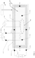
- Figure 2 presents a simplified side view of the front section, offering a schematic representation of both the charging (4) and discharging system (22).
- This schematic includes the integration of bundle pipes within the concrete walls and the base of the containment structure.
- the upper part of the containment structure functions as an opening (21), providing convenient access to the storage system.
- the system features an operational evaporation system (5).
- This system plays a pivotal role in reducing the water content in oily sludges and mill scale, incorporating a built-in filter (51).
- the inclusion of the filter enhances the environmental conditions of operation and significantly contributes to the overall impact of the invention.
- the filter improves system efficiency, aligning with the invention's goal of sustainable and environmentally friendly thermal energy storage.
- Evaporation serving as the initial stage of mill scale regeneration, further underscores the comprehensive and innovative approach of the entire system.
- the exhaust stream (52) is closed (53) to prevent thermal energy losses, emphasizing the careful consideration of design elements in the invention.
- Figure 3 represents an example of the invention's application for storing waste heat from processes in metallurgical production, utilizing oily mill scale waste.
- the illustration depicts three sections, each measuring 6 meters in length, 2 meters in width, and 2 meters in height.
- the design of the sections follows the concept outlined in Figure 1 . These sections are parallelly charged with steam at a maximum temperature of 400°C.
- the stored heat with a total capacity of 30 MWh at a temperature difference of T10 - T9 minimum 200°C, enables continuous production of approximately 200 kWh of electrical energy on an ORC turbine for approximately 36 hours.
- the sections do not utilize electric heating, which is primarily intended for balancing deviations in the power grid.
- Figure 4 illustrates the embodiment of the invention through eight thermal energy storage units, each measuring 6 x 2 x 2 meters and filled with oily mill scale waste.
- This design is specifically tailored to address the demand for short-term storage of excess electrical energy in the network during the shutdown of an electric arc furnace in a steelworks.
- the configuration enables the temporary capture of deviations up to 200 MW in the form of thermal energy for approximately 15 minutes. This captured thermal energy is continuously utilized in this example to supply hot water for centralized heating.
- the present invention represents a significant advancement in waste material integration into thermal energy storage systems. It offers a sustainable and effective solution for energy management, contributing to enhanced economic viability and environmental benefits.
Landscapes
- Engineering & Computer Science (AREA)
- Physics & Mathematics (AREA)
- Thermal Sciences (AREA)
- Mechanical Engineering (AREA)
- General Engineering & Computer Science (AREA)
- Waste-Gas Treatment And Other Accessory Devices For Furnaces (AREA)
Priority Applications (1)
| Application Number | Priority Date | Filing Date | Title |
|---|---|---|---|
| EP23474001.7A EP4575373A1 (fr) | 2023-12-20 | 2023-12-20 | Stockage d'énergie thermique hybride avec des boues huileuses et des calamines provenant d'aciéries |
Applications Claiming Priority (1)
| Application Number | Priority Date | Filing Date | Title |
|---|---|---|---|
| EP23474001.7A EP4575373A1 (fr) | 2023-12-20 | 2023-12-20 | Stockage d'énergie thermique hybride avec des boues huileuses et des calamines provenant d'aciéries |
Publications (1)
| Publication Number | Publication Date |
|---|---|
| EP4575373A1 true EP4575373A1 (fr) | 2025-06-25 |
Family
ID=89578584
Family Applications (1)
| Application Number | Title | Priority Date | Filing Date |
|---|---|---|---|
| EP23474001.7A Pending EP4575373A1 (fr) | 2023-12-20 | 2023-12-20 | Stockage d'énergie thermique hybride avec des boues huileuses et des calamines provenant d'aciéries |
Country Status (1)
| Country | Link |
|---|---|
| EP (1) | EP4575373A1 (fr) |
Citations (9)
| Publication number | Priority date | Publication date | Assignee | Title |
|---|---|---|---|---|
| JP2005241145A (ja) * | 2004-02-26 | 2005-09-08 | Jfe Engineering Kk | 熱交換装置及び熱交換装置の固相剥離方法 |
| WO2016099290A1 (fr) | 2014-12-19 | 2016-06-23 | Energynest As | Dispositif de stockage d'énergie thermique et d'échange de chaleur |
| WO2016099920A1 (fr) | 2014-12-19 | 2016-06-23 | Landis+Gyr Innovations, Inc. | Réseau maillé sans fil avec communication entre un dispositif aéroporté et un dispositif de métrologie fixe |
| WO2020136456A1 (fr) | 2018-12-28 | 2020-07-02 | Magaldi Power S.P.A. | Installation et procédé pour l'accumulation d'énergie sous forme thermique |
| EP3922939A1 (fr) | 2020-06-11 | 2021-12-15 | Vattenfall AB | Procédé de stockage d'énergie thermique, système de stockage thermique et utilisation d'un tel système de stockage thermique |
| EP3985340A1 (fr) | 2020-10-13 | 2022-04-20 | Siemens Gamesa Renewable Energy A/S | Installation de stockage d'énergie thermique |
| EP4043416A1 (fr) | 2021-02-12 | 2022-08-17 | Povazská cementáren, a.s. | Supports de stockage d'énergie thermique à base de béton et utilisation de ciment hybride en tant que liant pour la production de tels supports en béton |
| US11499783B2 (en) * | 2019-03-29 | 2022-11-15 | Mitsubishi Electric Corporation | Heating and/or cooling system and method for reducing or removing solidified phase change material |
| US20230258419A1 (en) * | 2022-02-14 | 2023-08-17 | Advanced Materials Scientia LLC | Low-cost engineered particles for thermal energy transfer or storage |
-
2023
- 2023-12-20 EP EP23474001.7A patent/EP4575373A1/fr active Pending
Patent Citations (9)
| Publication number | Priority date | Publication date | Assignee | Title |
|---|---|---|---|---|
| JP2005241145A (ja) * | 2004-02-26 | 2005-09-08 | Jfe Engineering Kk | 熱交換装置及び熱交換装置の固相剥離方法 |
| WO2016099290A1 (fr) | 2014-12-19 | 2016-06-23 | Energynest As | Dispositif de stockage d'énergie thermique et d'échange de chaleur |
| WO2016099920A1 (fr) | 2014-12-19 | 2016-06-23 | Landis+Gyr Innovations, Inc. | Réseau maillé sans fil avec communication entre un dispositif aéroporté et un dispositif de métrologie fixe |
| WO2020136456A1 (fr) | 2018-12-28 | 2020-07-02 | Magaldi Power S.P.A. | Installation et procédé pour l'accumulation d'énergie sous forme thermique |
| US11499783B2 (en) * | 2019-03-29 | 2022-11-15 | Mitsubishi Electric Corporation | Heating and/or cooling system and method for reducing or removing solidified phase change material |
| EP3922939A1 (fr) | 2020-06-11 | 2021-12-15 | Vattenfall AB | Procédé de stockage d'énergie thermique, système de stockage thermique et utilisation d'un tel système de stockage thermique |
| EP3985340A1 (fr) | 2020-10-13 | 2022-04-20 | Siemens Gamesa Renewable Energy A/S | Installation de stockage d'énergie thermique |
| EP4043416A1 (fr) | 2021-02-12 | 2022-08-17 | Povazská cementáren, a.s. | Supports de stockage d'énergie thermique à base de béton et utilisation de ciment hybride en tant que liant pour la production de tels supports en béton |
| US20230258419A1 (en) * | 2022-02-14 | 2023-08-17 | Advanced Materials Scientia LLC | Low-cost engineered particles for thermal energy transfer or storage |
Similar Documents
| Publication | Publication Date | Title |
|---|---|---|
| US12516613B1 (en) | Thermal energy storage system coupled with thermal power cycle systems | |
| Tetteh et al. | Cost-effective Electro-Thermal Energy Storage to balance small scale renewable energy systems | |
| Lazzarin et al. | Energy efficiency opportunities in the production process of cast iron foundries: An experience in Italy | |
| EP3172413B2 (fr) | Centrale électrique à cycle vapeur et système d'échange d'énergie thermique à haute température et procédé de fabrication de centrale électrique | |
| Amiri et al. | Progress on rock thermal energy storage (RTES): A state of the art review | |
| Bauer | Fundamentals of high-temperature thermal energy storage, transfer, and conversion | |
| CN102287868B (zh) | 移动利用余热蒸汽的方法及供应蒸汽、热水的移动蓄热车 | |
| Acar et al. | Better thermal management options with heat storage systems for various applications: An Evaluation | |
| Steinparzer et al. | Heat exchangers and thermal energy storage concepts for the off-gas heat of steelmaking devices | |
| Abushamah et al. | Integration of district heating systems with small modular reactors and organic Rankine cycle including energy storage: Design and energy management optimization | |
| Rahbari et al. | Energy, exergy, economic and environmental analyses of air-based high-temperature thermal energy and electricity storage: impacts of off-design operation | |
| EP4575373A1 (fr) | Stockage d'énergie thermique hybride avec des boues huileuses et des calamines provenant d'aciéries | |
| CN103397940A (zh) | 一种基于压缩空气及余能回收的复合蓄能发电系统 | |
| Rahjoo et al. | Reviewing numerical studies on sensible thermal energy storage in cementitious composites: report of the RILEM TC 299-TES | |
| Ma et al. | Thermal energy storage for energy decarbonizatioN | |
| Erdemir | Development and assessment of geothermal‐based underground pumped hydroenergy storage system integrated with organic Rankine cycle and district heating | |
| Martin et al. | Industrial applications of thermal energy storage systems | |
| CN103557078A (zh) | 一种基于余热再热的压缩空气蓄能发电系统 | |
| US12359591B1 (en) | Thermal energy storage systems for repowering existing power plants for improving efficiency and safety | |
| KR101263941B1 (ko) | 폐열 회수를 이용한 발전시스템 | |
| CN102321773A (zh) | 一种高炉冲渣水低温热电转换系统 | |
| CN104654810A (zh) | 一种工业流体热能蓄热式回收利用器 | |
| CN103411459A (zh) | 多能源高温蓄热节能装置 | |
| CN203742828U (zh) | 蓄热式斯特林发电机组及移动机组 | |
| US12607170B2 (en) | Thermal energy storage system for use with a low temperature heat source and a thermal power cycle system |
Legal Events
| Date | Code | Title | Description |
|---|---|---|---|
| PUAI | Public reference made under article 153(3) epc to a published international application that has entered the european phase |
Free format text: ORIGINAL CODE: 0009012 |
|
| STAA | Information on the status of an ep patent application or granted ep patent |
Free format text: STATUS: THE APPLICATION HAS BEEN PUBLISHED |
|
| AK | Designated contracting states |
Kind code of ref document: A1 Designated state(s): AL AT BE BG CH CY CZ DE DK EE ES FI FR GB GR HR HU IE IS IT LI LT LU LV MC ME MK MT NL NO PL PT RO RS SE SI SK SM TR |
|
| STAA | Information on the status of an ep patent application or granted ep patent |
Free format text: STATUS: THE APPLICATION IS DEEMED TO BE WITHDRAWN |