EP4575417A1 - Armature interchangeable destinée à être agencée sur un récipient rempli de milieu, procédé d'équipement d'une armature interchangeable avec un capteur et procédé d'introduction d'une lance de mesure dans un milieu - Google Patents
Armature interchangeable destinée à être agencée sur un récipient rempli de milieu, procédé d'équipement d'une armature interchangeable avec un capteur et procédé d'introduction d'une lance de mesure dans un milieu Download PDFInfo
- Publication number
- EP4575417A1 EP4575417A1 EP23218700.5A EP23218700A EP4575417A1 EP 4575417 A1 EP4575417 A1 EP 4575417A1 EP 23218700 A EP23218700 A EP 23218700A EP 4575417 A1 EP4575417 A1 EP 4575417A1
- Authority
- EP
- European Patent Office
- Prior art keywords
- measuring
- gear
- rotor
- measuring lance
- lance
- Prior art date
- Legal status (The legal status is an assumption and is not a legal conclusion. Google has not performed a legal analysis and makes no representation as to the accuracy of the status listed.)
- Pending
Links
Images


Classifications
-
- G—PHYSICS
- G01—MEASURING; TESTING
- G01D—MEASURING NOT SPECIALLY ADAPTED FOR A SPECIFIC VARIABLE; ARRANGEMENTS FOR MEASURING TWO OR MORE VARIABLES NOT COVERED IN A SINGLE OTHER SUBCLASS; TARIFF METERING APPARATUS; MEASURING OR TESTING NOT OTHERWISE PROVIDED FOR
- G01D11/00—Component parts of measuring arrangements not specially adapted for a specific variable
- G01D11/24—Housings ; Casings for instruments
- G01D11/245—Housings for sensors
-
- G—PHYSICS
- G01—MEASURING; TESTING
- G01D—MEASURING NOT SPECIALLY ADAPTED FOR A SPECIFIC VARIABLE; ARRANGEMENTS FOR MEASURING TWO OR MORE VARIABLES NOT COVERED IN A SINGLE OTHER SUBCLASS; TARIFF METERING APPARATUS; MEASURING OR TESTING NOT OTHERWISE PROVIDED FOR
- G01D11/00—Component parts of measuring arrangements not specially adapted for a specific variable
- G01D11/30—Supports specially adapted for an instrument; Supports specially adapted for a set of instruments
-
- G—PHYSICS
- G01—MEASURING; TESTING
- G01N—INVESTIGATING OR ANALYSING MATERIALS BY DETERMINING THEIR CHEMICAL OR PHYSICAL PROPERTIES
- G01N27/00—Investigating or analysing materials by the use of electric, electrochemical, or magnetic means
- G01N27/26—Investigating or analysing materials by the use of electric, electrochemical, or magnetic means by investigating electrochemical variables; by using electrolysis or electrophoresis
- G01N27/28—Electrolytic cell components
- G01N27/283—Means for supporting or introducing electrochemical probes
Definitions
- the present invention relates to a retractable fitting for arranging on a container filled with medium according to claim 1. Furthermore, the invention relates to a method for equipping a retractable fitting according to claim 10 and a method for inserting a measuring lance into a medium according to claim 11.
- Retractable housings are typically used to perform measurements in an at least partially stagnant or flowing medium contained within a container.
- a container include a closed pipeline or a fully or partially closed process vessel.
- Retractable housings are particularly important in the process industry for liquid analysis.
- the medium in the container can be a liquid, a gas, or a free-flowing solid (powder), or a mixture thereof.
- Retractable fittings typically comprise a measuring probe designed to accommodate a sensor and a mounting element.
- the measuring probe is slidably mounted on the mounting element.
- the fastening element is connected to the container via a flange or another type of process connection, whereby the fastening element is arranged on the container in such a way that the measuring probe projects into the container in a measuring position: In the measuring position, a terminal area of the measuring probe projects beyond the fastening element, so that a measuring area of the measuring probe, which can be, for example, a measuring window for optical measurements or a measuring opening for the direct Contact of a sensor with the medium can have, with the medium in the container is in contact.
- a measuring area of the measuring probe which can be, for example, a measuring window for optical measurements or a measuring opening for the direct Contact of a sensor with the medium can have, with the medium in the container is in contact.
- the measuring area of the measuring probe is retracted and located within the fastening element, whereby the measuring area is sealed against the medium in the container.
- the measuring probe can be shifted manually or automatically via pneumatic displacement.
- a retractable fitting which pneumatically enables the movement of the measuring lance between the rest position and the measuring position.
- the present invention is therefore based on the object of providing an energy-efficient and flexibly usable retractable fitting and a method for its installation and operation, which enables a compact design of the retractable fitting.
- this object is achieved by a retractable fitting for arranging on a container filled with medium according to claim 1.
- the retractable fitting according to the invention for mounting on a container filled with a medium comprises a fastening element, a measuring probe, and an adjustment device.
- the fastening element is designed for mounting on the container.
- the measuring probe is designed to accommodate a sensor.
- the measuring probe is mounted on the fastening element so that it can be displaced along a displacement axis.
- the adjustment device is designed to interact with the fastening element and the measuring lance in order to move the measuring lance along the displacement axis.
- the adjustment device By means of the adjustment device, several positions can be reached by moving the measuring lance along the displacement axis, so that in particular a sensor arranged in the measuring lance can be moved into different positions.
- the adjusting device has an electric motor with a rotor and a stator, that at least the rotor has a recess and that the displacement axis runs through the recess of the rotor.
- an electric motor as part of the adjustment device is that the electric drive is energy-efficient, as it only consumes energy when a displacement is required. In comparison, pneumatic systems require continuously applied compressed air, resulting in higher energy consumption. Furthermore, the electric drive is independent of external compressed air sources, which increases the flexibility of using the retractable fitting according to the invention, particularly when used in complex process plants or on vessels or pipes located outdoors where no nearby compressed air source is available.
- a further advantage is that the retractable fitting according to the invention is less susceptible to certain types of wear or leakage that occur with pneumatic systems. This leads to increased reliability and lower maintenance costs.
- the use of a rotor with a recess through which the displacement axis runs has the advantage of achieving a compact design by arranging the displacement axis in the rotor recess. This enables efficient use of the available space and contributes to the flexible use of the retractable housing in various environments, even in confined spaces.
- This arrangement also offers the advantage of quickly and easily positioning a sensor in the measuring probe. This significantly simplifies maintenance and replacement work, which in turn reduces downtime and improves the availability of the retractable housing.
- the measuring lance preferably has a measuring area for performing a measurement on the medium in the container when the measuring device is arranged on the container.
- the measuring area can be designed as a measuring window, in particular as a radiation-permeable window, in order to perform a preferably optical measurement on the medium using the sensor arranged in the measuring lance.
- the measuring area can be designed as an opening in the measuring lance, so that the sensor arranged in the measuring lance is in direct contact with the medium in the container during the measurement.
- the measuring lance is arranged displaceably on the fastening element between a measuring position and a rest position, so that in the measuring position at least the measuring range of the measuring lance projects beyond the fastening element and in the rest position the measuring range of the measuring lance is arranged within the fastening element and the adjusting device is designed to cooperate with the fastening element and the measuring lance in order to displace the measuring lance between the measuring position and the rest position.
- the measuring area projecting beyond the fastening element in the measuring position is thus in contact with the medium of the container in the usage configuration when the retractable fitting is arranged on the container, so that a measurement can be carried out on the medium.
- the retractable assembly is preferably designed such that, when the measuring probe is in the rest position, the measuring area of the measuring probe is fluid-tightly sealed against the medium in the container. This offers the advantage that the sensor is not exposed to the medium in the rest position and can be flushed, calibrated, and/or replaced without medium from the container penetrating the measuring probe or the retractable assembly.
- the retractable assembly is designed such that the measuring probe is arranged in the recess of the rotor at least in one of the measuring position and the rest position, preferably at least in the rest position.
- the measuring probe is guided in the recess of the rotor throughout the entire displacement path between the measuring position and the rest position.
- Another advantage is that the position of the measuring probe in the recess of the rotor helps to protect the measuring probe from external influences, especially from possible mechanical influences.
- the electric motor of the retractable assembly is designed as a hollow-shaft motor, and the displacement axis runs within the hollow shaft of the hollow-shaft motor.
- the measuring probe is preferably arranged displaceably within the hollow shaft of the hollow-shaft motor, with the displacement axis of the measuring probe preferably being arranged parallel to a longitudinal axis of the hollow shaft of the hollow-shaft motor.
- the electric motor of the adjustment device is designed such that the rotor is arranged within the stator. This results in a compact design, since the stator can be connected to an outer housing of the retractable fitting.
- the electric motor of the adjusting device is designed as a brushless DC motor and/or as a stepper motor.
- a preferred embodiment of the electric motor as a brushless DC motor offers the advantage of low maintenance. Furthermore, thanks to reduced wear, it has a longer service life.
- a preferred embodiment of the electric motor as a stepper motor offers the advantage of low maintenance, as it requires no brushes or commutators. Furthermore, a stepper motor enables precise positioning of the measuring probe.
- the electric motor of the adjusting device is particularly advantageous to design the electric motor of the adjusting device as a reluctance motor, in particular as a switched reluctance motor or a synchronous reluctance motor.
- the electric motor as a reluctance motor is that it does not require rare earths for the production of permanent magnets. Reduces dependence on limited and environmentally damaging resources that arise from the mining and processing of rare earths.
- the reluctance motor is therefore free of rare earths.
- the measuring lance has at least one rack
- the adjusting device is designed to transmit the rotational movement of the electric motor to the rack by means of at least one gear of the adjusting device to form a linear displacement movement.
- the rotor is directly connected to the measuring probe, particularly without an intermediate gear, to effect the displacement of the measuring probe. This results in the advantage of saving mechanical components compared to the use of a gear.
- the rotor is operatively connected to the measuring lance, preferably indirectly via a gear mechanism of the retractable assembly, in order to effect the displacement of the measuring lance.
- the adjustment device therefore has a gear mechanism whose drive is operatively connected to the electric motor and whose output is operatively connected to the measuring lance. This enables a higher force to be applied to the measuring lance by means of the electric motor compared to a design without a gear mechanism. In particular, this allows the use of compact electric motors whose torque would not allow the required force to be applied to the measuring lance without the use of a gear mechanism.
- the gear mechanism can have one or more gear mechanisms.
- the transmission device comprises a mechanical transmission, in particular a positive-locking transmission.
- the transmission device has a cycloidal gear in order to achieve a compact design and due to the advantages mentioned below.
- the transmission device preferably comprises a helical gear, preferably with a spindle drive and a threaded spindle, to convert a rotary movement of the electric motor into a linear movement of the measuring lance.
- a helical gear preferably with a spindle drive and a threaded spindle, to convert a rotary movement of the electric motor into a linear movement of the measuring lance.
- the output of the electric motor is connected to the helical gear without the interposition of another gear.
- the gear device comprises, in addition to the helical gear, at least one other gear, preferably exactly one other gear, in particular a gear from the list of gears listed above, preferably a cycloidal gear.
- the spindle drive of the gear mechanism comprises a threaded spindle and a spindle nut, wherein the spindle nut is rotatably mounted on the threaded spindle, and wherein the electric motor is operatively connected to the spindle nut to rotate the spindle nut.
- the measuring lance is advantageous to design the measuring lance as a threaded spindle.
- the compact design is advantageous, which is preferably achieved by designing the measuring lance as a spindle drive, in particular as a threaded rod.
- the transmission device comprises a ball screw drive.
- the reduced friction provided by the balls is advantageous here.
- a further advantage of using the measuring lance designed as a threaded spindle as part of the spindle drive is that it enables a low-friction and precise linear movement of the measuring lance.
- the measuring probe is designed as a threaded spindle in multiple pieces. This advantageously reduces manufacturing costs.
- the adjustment device comprises a gear mechanism with a cycloidal gear and a spindle drive, wherein the cycloidal gear is designed to transmit the torque generated by the electric motor to the spindle drive.
- the compact design of cycloidal gears is advantageous in this case, allowing efficient use of the available space in the retractable assembly.
- Another advantage is that the use of cycloidal gears can reduce maintenance costs, as cycloidal gears are less susceptible to wear due to their design.
- Another advantage is that a high gear ratio can be achieved in a small installation space, since the design of cycloidal gears allows for a large gear ratio in a small installation space.
- the combination of cycloidal gearing and spindle drive enables a compact design of the adjustment device. This is particularly advantageous for efficient use of the available installation space. Furthermore, the spindle drive has a self-locking feature, which ensures that the measuring probe remains stable in its actual position and is not accidentally displaced.
- the cycloidal gear of the gear device has a recess, and the displacement direction of the measuring lance runs through this recess of the cycloidal gear.
- the measuring lance is preferably arranged in the recess of the cycloidal gear at least in the rest position and/or in the measuring position. The measuring lance is preferably guided in the recess of the cycloidal gear during the displacement path between the rest position and the measuring position. This results in a compact and robust design.
- the cycloidal gear of the gearing device is arranged between the electric motor and the side of the fastening element designed for arrangement on the container.
- the cycloidal gear is designed as a cycloidal eccentric gear, preferably as a multiple cycloidal eccentric gear, particularly preferably as a double cycloidal eccentric gear.
- a multiple cycloidal gear several cycloidal discs are used, which are arranged offset from one another.
- two cycloidal discs offset by 180° are used. The advantage here is that the imbalance caused by the eccentric is compensated. This leads to smoother running and reduces the load on the components.
- the transmission device comprises a belt and pulleys, wherein at least one of the pulleys is connected to the electric motor, and the measuring probe is movable by means of the belt. This enables an efficient and cost-effective transmission of the rotational movement into a linear movement.
- the adjusting device comprises a gear mechanism with a planetary gear or a shaft gear, wherein the planetary gear or the shaft gear is designed to transmit the torque generated by the electric motor to the spindle drive.
- the gear mechanism comprises a ball screw with a spindle with ball bearings, by means of which the measuring lance is movable. It is advantageous here to ensure the low-friction movement of the components and the precise positioning of the measuring probe, which improves the longevity and precision of the retractable fitting.
- the transmission device comprises a rack with a gearwheel, wherein the gearwheel is connected to the cycloidal gear, and wherein the measuring probe is designed, at least in sections, as a rack.
- the adjusting device comprises a bevel gear, wherein the ring gear of the bevel gear is connected to the rotor of the electric motor and the pinion of the bevel gear is connected to a gear, and wherein the measuring lance is designed, at least in sections, as a rack.
- the gear engages with the rack of the measuring lance, so that a rotational movement of the gear causes the measuring lance to be displaced linearly.
- the adjusting device has a manual actuation mechanism, which is designed to move the measuring lance between the measuring position and the rest position by manual actuation.
- the manual operating mechanism enables manual emergency operation.
- the retractable assembly is de-energized and the electrical components are thus decoupled.
- the manual operating mechanism has a manual operating element, preferably a lever or a wheel.
- This manual operating element is accessible to the user and allows the measuring probe to be moved between the measuring position and the rest position, for example, by a rotational movement.
- the manual operating element is preferably detachably attached to the retractable assembly.
- the rotor is rotated by the rotational movement of the manual actuating element.
- the adjustment device has a locking mechanism that releases the manual actuation mechanism for manual actuation. This prevents the manual actuation mechanism from being used inadvertently. Furthermore, manual actuation while the valve is energized can be prevented.
- the locking mechanism also facilitates maintenance and inspection work.
- the retractable assembly has at least one intermediate position between the measuring position and the rest position, wherein the adjustment device is configured to selectively move the measuring probe into the measuring position, intermediate position, and rest position.
- the retractable assembly comprises an additional shielding element, which serves to shield against unwanted electromagnetic interference and improve the electromagnetic compatibility of the retractable assembly.
- the shielding element is made of an electrically conductive material. This measure contributes to improving the reliability and interference immunity of the retractable assembly in various operating environments. In particular, this measure helps prevent interference with electronic components, especially measurement technology.
- the retractable assembly comprises an additional braking element that serves to prevent the movement of the measuring probe when it is in the measuring position, the rest position, or an intermediate position.
- the braking element is preferably designed as a simple detent, particularly preferably as a conical brake. This is advantageous because the measuring probe is prevented from moving when the electric motor is de-energized. This is particularly advantageous when the medium in the container is under pressure, as this can lead to undesired displacement of the measuring probe.
- the measuring probe is arranged centrally in the recess of the cycloidal gear and centrally in the recess of the rotor, so that the cycloidal gear and the rotor are arranged concentrically around the measuring probe.
- a further advantage is that the concentric arrangement enables a more compact design.
- the retractable assembly has a cleaning device with a fluid-tight rinsing chamber and a rinsing medium supply.
- the rinsing chamber has a recess through which the measuring probe is arranged at least in the measuring position, and in which the measuring probe is arranged in an intermediate position at least with the measuring range of the measuring probe.
- the deposits or contaminants that accumulate in the measuring range of the measuring probe due to contact with the medium in the container can be cleaned in the rinsing chamber using a rinsing medium. This improves the measurement accuracy and thus increases the reliability of the medium measurement.
- the retractable assembly has a travel protection device to prevent the measuring probe from being moved without a sensor inserted into it,
- the travel protection creates an additional safety layer to prevent unwanted movement of the measuring probe.
- the fastening element is designed such that the fastening element, in particular a receptacle of the fastening element, extends into the interior of the container when the retractable fitting is arranged on the container.
- the measuring range of the measuring lance is located inside the container even in the rest position.
- the measuring range is arranged in the fastening element in the rest position and thus, although the measuring range is also located inside the container in the rest position, there is no contact between the medium and the measuring range of the measuring lance due to the shielding provided by the fastening element.
- the advantage here is the precise sensor placement, as insertion through the recess in the rotor ensures accurate positioning.
- Another advantage is that the method allows for the use of a compact retractable housing. Furthermore, the method is advantageous because it prevents sensor contamination, as guiding the sensor through the recess in the rotor reduces the risk of contamination.
- Another advantage is that consistent sensor alignment is achieved, as the recess in the rotor ensures consistent sensor alignment.
- the retractable fitting is designed as a retractable fitting according to the invention, in particular a preferred embodiment thereof.
- the targeted movement, particularly displacement along a straight axis of the measuring probe within the rotor recess, is advantageous, as this leads to precise positioning in the medium.
- Another advantage is the minimization of contamination, as the targeted movement within the recess reduces the risk of contamination and protects the measuring probe from external influences.
- Another advantage is that this method enables a compact design of the retractable housing.
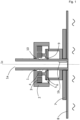
- the Figure 1 shows a schematic representation of a first embodiment of a retractable assembly according to the invention.
- the retractable assembly has a fastening element 7, which is arranged on a container 8 filled with medium.
- the retractable assembly has an adjusting device with an electric motor, wherein the electric motor a rotor 4 and a stator 3.
- the measuring probe 1 has a cavity 1a into which a sensor can be inserted; this sensor is not shown in the figure.
- the measuring probe 1 is arranged on the fastening element 1 so that it can be linearly displaced along the displacement axis 1c.
- the fastening element 7 has a flange-shaped base which has a recess.
- the fastening element 7 further comprises a housing 2 of the retractable fitting.
- the housing 2 in this case has a rotationally symmetrical shape with an upper and a lower recess.
- the housing 2 encloses a cavity in which the adjustment unit with its electric motor, which in this embodiment is designed as a switched reluctance motor, is arranged.
- the stator teeth of the stator 3 are wound with coils, and the rotor 4 has a central recess, wherein the recess of the rotor 4 and the upper and lower recesses of the housing 2 are coaxially aligned.
- the stator 3 is connected to the housing 2, and the rotor 4 is rotatably mounted.
- the measuring probe 1 of the retractable assembly is positioned centrally through the recess of the rotor 4, as well as through the upper and lower recesses of the housing 2. In the illustrated embodiment, the measuring probe 1 is in the rest position. In the rest position, the measuring probe 1 is not inserted into the container 8.
- the measuring probe 1 has a measuring area 1b, which in this case is designed as a glass window.
- the sensor arranged in the measuring probe 1 thus allows a contactless, optical measurement of the medium through the glass window.
- the measuring area 1b is designed as an opening in the measuring probe, allowing direct contact between the sensor and the medium.
- the measuring probe is in the rest position so that the measuring area is in the fastening element and there is no contact between the measuring area and the medium.
- the adjustment unit has a gear device with a cycloidal gear and a spindle drive, wherein the cycloidal gear is designed to transmit the torque applied by the electric motor to the spindle drive.
- the measuring probe 1 has an external thread and thus forms the threaded spindle 10 of the spindle drive. Furthermore, the spindle drive has a spindle nut 9.
- the cam disc When the rotor 4 drives the eccentric shaft 5, the cam disc is moved eccentrically, causing the cam disc to rotate around its axis of symmetry. Holes are provided in the cam disc that rotate relative to the eccentric shaft 5. The rollers of the roller disc 6 engage in these holes. In this way, the cam disc drives the roller disc 6, on which the centrally mounted output shaft is also located and sits coaxially with the input shaft.
- the spindle nut 9 connected to the drive shaft is arranged to engage the threaded spindle 10 of the measuring lance 1, so that the rotational movement of the spindle nut 9 leads to a translational movement of the measuring lance 1.
- the rotational movement of the spindle nut 9 is converted into a linear movement of the measuring lance 1 via the threaded spindle 10.
- the retractable assembly includes a rotary encoder.
- this rotary encoder is equipped with Hall sensors.
- the rotary encoder includes optical sensors for position determination.
- FIG 2 The measuring probe is shown in its measuring position, with the measuring probe 1 protruding into the container 8 filled with medium.
- the measuring area 1b is in contact with the medium to enable a measurement.
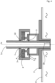
- FIG 3 a second embodiment of a retractable fitting according to the invention is shown, which differs from the embodiment in Figure 1 and 2 differs in that the gear mechanism has a measuring lance 1 designed as a rack 12 instead of a spindle drive, and the cycloidal gear is connected via a ring gear and a pinion to a gear 11 engaging with the rack 12.
- the rotary movement of the ring gear is converted via the pinion and the gear 11 connected thereto into a linear movement of the measuring lance 1 designed as a rack 2.
- Figure 4 shows a modification of the Figure 1 To avoid repetition, only the main differences are discussed below:
- the fastening element 7 is designed such that it projects into the container 8.
- the measuring probe 1 is in the rest position. Even in the rest position, the lower end of the measuring probe and, in particular, the measuring area 1b are located inside the container 8. However, the measuring area is also located inside the fastening element 7 and is thus shielded from the medium, so that in the rest position there is no contact between the medium and the measuring area 1b.
- the measuring probe In the measuring position (not shown), the measuring probe is analogous to the illustration in Figure 2 moved downwards so that the lower end of the measuring probe 1 is above the fastening element 7 and the measuring area 1b is in direct contact with the medium.
Landscapes
- Physics & Mathematics (AREA)
- General Physics & Mathematics (AREA)
- Length Measuring Devices With Unspecified Measuring Means (AREA)
Priority Applications (2)
| Application Number | Priority Date | Filing Date | Title |
|---|---|---|---|
| EP23218700.5A EP4575417A1 (fr) | 2023-12-20 | 2023-12-20 | Armature interchangeable destinée à être agencée sur un récipient rempli de milieu, procédé d'équipement d'une armature interchangeable avec un capteur et procédé d'introduction d'une lance de mesure dans un milieu |
| US18/978,392 US20250207957A1 (en) | 2023-12-20 | 2024-12-12 | Retractable probe housing for attaching to a container filled with medium, method for equipping a retractable probe housing with a sensor and method for inserting a measuring probe into a medium |
Applications Claiming Priority (1)
| Application Number | Priority Date | Filing Date | Title |
|---|---|---|---|
| EP23218700.5A EP4575417A1 (fr) | 2023-12-20 | 2023-12-20 | Armature interchangeable destinée à être agencée sur un récipient rempli de milieu, procédé d'équipement d'une armature interchangeable avec un capteur et procédé d'introduction d'une lance de mesure dans un milieu |
Publications (1)
| Publication Number | Publication Date |
|---|---|
| EP4575417A1 true EP4575417A1 (fr) | 2025-06-25 |
Family
ID=89224691
Family Applications (1)
| Application Number | Title | Priority Date | Filing Date |
|---|---|---|---|
| EP23218700.5A Pending EP4575417A1 (fr) | 2023-12-20 | 2023-12-20 | Armature interchangeable destinée à être agencée sur un récipient rempli de milieu, procédé d'équipement d'une armature interchangeable avec un capteur et procédé d'introduction d'une lance de mesure dans un milieu |
Country Status (2)
| Country | Link |
|---|---|
| US (1) | US20250207957A1 (fr) |
| EP (1) | EP4575417A1 (fr) |
Citations (3)
| Publication number | Priority date | Publication date | Assignee | Title |
|---|---|---|---|---|
| EP2530461A2 (fr) * | 2011-05-30 | 2012-12-05 | Andree Gilhofer | Procédé et dispositif d'entretien, nettoyage et calibrage possibles de l'extérieur de dispositifs de mesure électroanalytiques dans la boue |
| DE102012200438A1 (de) | 2012-01-12 | 2013-07-18 | Detlef Exner | Wechselarmatur für ein Behältnis, Verfahren zum Anbringen einer Wechselarmatur an ein Behältnis und Verwendung einer Wechselarmatur |
| WO2013163607A1 (fr) * | 2012-04-27 | 2013-10-31 | Rohrback Cosasco Systems, Inc. | Outil de récupération magnétique |
-
2023
- 2023-12-20 EP EP23218700.5A patent/EP4575417A1/fr active Pending
-
2024
- 2024-12-12 US US18/978,392 patent/US20250207957A1/en active Pending
Patent Citations (3)
| Publication number | Priority date | Publication date | Assignee | Title |
|---|---|---|---|---|
| EP2530461A2 (fr) * | 2011-05-30 | 2012-12-05 | Andree Gilhofer | Procédé et dispositif d'entretien, nettoyage et calibrage possibles de l'extérieur de dispositifs de mesure électroanalytiques dans la boue |
| DE102012200438A1 (de) | 2012-01-12 | 2013-07-18 | Detlef Exner | Wechselarmatur für ein Behältnis, Verfahren zum Anbringen einer Wechselarmatur an ein Behältnis und Verwendung einer Wechselarmatur |
| WO2013163607A1 (fr) * | 2012-04-27 | 2013-10-31 | Rohrback Cosasco Systems, Inc. | Outil de récupération magnétique |
Also Published As
| Publication number | Publication date |
|---|---|
| US20250207957A1 (en) | 2025-06-26 |
Similar Documents
| Publication | Publication Date | Title |
|---|---|---|
| EP2315648B1 (fr) | Unité d'entraînement comprenant un premier et un deuxième moteurs | |
| EP1169582B1 (fr) | Dispositif de commande de boite planetaire a deux vitesses | |
| WO2010060647A1 (fr) | Unité de motoréducteur électrique | |
| WO2015144147A1 (fr) | Actionneur pour une boîte de vitesses de véhicule à moteur | |
| EP3079862A1 (fr) | Dispositif d'entraînement pour un dispositif de préhension | |
| EP2295147A1 (fr) | Système d'entraînement de moulin | |
| EP3460149B1 (fr) | Actionneur, mécanisme de verrouillage, verrou électromécanique ainsi que leur utilisation et procédé correspondant | |
| EP0461357A2 (fr) | Tourelle révolver porte outil | |
| EP3612752A1 (fr) | Dispositif d'entraînement pour poussoir mobile | |
| DE102013107378A1 (de) | Antriebsvorrichtung | |
| EP4575417A1 (fr) | Armature interchangeable destinée à être agencée sur un récipient rempli de milieu, procédé d'équipement d'une armature interchangeable avec un capteur et procédé d'introduction d'une lance de mesure dans un milieu | |
| WO2008009299A1 (fr) | Unité d'assemblage | |
| DE102014204069A1 (de) | Ventilscheibe | |
| EP3977494B1 (fr) | Commutateur pour un outil èlectrique à main | |
| DE102006025704B3 (de) | Verfahren und Vorrichtung zum Betätigen einer Parkbremse | |
| EP2769393A1 (fr) | Dispositif de commande électronique pour commander des actionneurs | |
| DE19719510A1 (de) | Vorrichtung zur Umwandlung einer Drehbewegung in eine geradlinige Bewegung | |
| EP3468009B1 (fr) | Module de mouvements rotatifs/verticaux destiné aux mouvements rotatifs et/ou linéaires d'un élément de travail | |
| DE102011082828A1 (de) | Schalteinheit mit Spindeltrieb für ein Werkzeugmaschinengetriebe | |
| DE102015105483B4 (de) | Ventilantrieb | |
| DE10004707C2 (de) | Selbstverstellende Schrauberanordnung | |
| EP2475498A1 (fr) | Table de transfert circulaire comprenant un entraînement direct de la came de transport | |
| DE10235069A1 (de) | Spindelvorrichtung für eine Werkzeugmaschine | |
| DE102014224500A1 (de) | Ventil-Betätigungsvorrichtung mit mehrstufigem Zahnradgetriebe | |
| DE102015201160A1 (de) | Bürstenloser Gleichstrommotor |
Legal Events
| Date | Code | Title | Description |
|---|---|---|---|
| PUAI | Public reference made under article 153(3) epc to a published international application that has entered the european phase |
Free format text: ORIGINAL CODE: 0009012 |
|
| STAA | Information on the status of an ep patent application or granted ep patent |
Free format text: STATUS: THE APPLICATION HAS BEEN PUBLISHED |
|
| AK | Designated contracting states |
Kind code of ref document: A1 Designated state(s): AL AT BE BG CH CY CZ DE DK EE ES FI FR GB GR HR HU IE IS IT LI LT LU LV MC ME MK MT NL NO PL PT RO RS SE SI SK SM TR |
|
| STAA | Information on the status of an ep patent application or granted ep patent |
Free format text: STATUS: REQUEST FOR EXAMINATION WAS MADE |
|
| 17P | Request for examination filed |
Effective date: 20251217 |