EP4575448A1 - Verfahren zur bestimmung von parameterwerten eines optischen systems - Google Patents
Verfahren zur bestimmung von parameterwerten eines optischen systems Download PDFInfo
- Publication number
- EP4575448A1 EP4575448A1 EP23307280.0A EP23307280A EP4575448A1 EP 4575448 A1 EP4575448 A1 EP 4575448A1 EP 23307280 A EP23307280 A EP 23307280A EP 4575448 A1 EP4575448 A1 EP 4575448A1
- Authority
- EP
- European Patent Office
- Prior art keywords
- optical element
- power
- optical system
- front optical
- wearer
- Prior art date
- Legal status (The legal status is an assumption and is not a legal conclusion. Google has not performed a legal analysis and makes no representation as to the accuracy of the status listed.)
- Pending
Links
Images


Classifications
-
- G—PHYSICS
- G01—MEASURING; TESTING
- G01M—TESTING STATIC OR DYNAMIC BALANCE OF MACHINES OR STRUCTURES; TESTING OF STRUCTURES OR APPARATUS, NOT OTHERWISE PROVIDED FOR
- G01M11/00—Testing of optical apparatus; Testing structures by optical methods not otherwise provided for
- G01M11/02—Testing optical properties
- G01M11/0228—Testing optical properties by measuring refractive power
-
- G—PHYSICS
- G02—OPTICS
- G02B—OPTICAL ELEMENTS, SYSTEMS OR APPARATUS
- G02B27/00—Optical systems or apparatus not provided for by any of the groups G02B1/00 - G02B26/00, G02B30/00
- G02B27/01—Head-up displays
- G02B27/017—Head mounted
- G02B27/0172—Head mounted characterised by optical features
-
- G—PHYSICS
- G02—OPTICS
- G02C—SPECTACLES; SUNGLASSES OR GOGGLES INSOFAR AS THEY HAVE THE SAME FEATURES AS SPECTACLES; CONTACT LENSES
- G02C7/00—Optical parts
- G02C7/02—Lenses; Lens systems ; Methods of designing lenses
- G02C7/024—Methods of designing ophthalmic lenses
-
- G—PHYSICS
- G02—OPTICS
- G02C—SPECTACLES; SUNGLASSES OR GOGGLES INSOFAR AS THEY HAVE THE SAME FEATURES AS SPECTACLES; CONTACT LENSES
- G02C7/00—Optical parts
- G02C7/02—Lenses; Lens systems ; Methods of designing lenses
- G02C7/06—Lenses; Lens systems ; Methods of designing lenses bifocal; multifocal ; progressive
- G02C7/061—Spectacle lenses with progressively varying focal power
-
- G—PHYSICS
- G02—OPTICS
- G02C—SPECTACLES; SUNGLASSES OR GOGGLES INSOFAR AS THEY HAVE THE SAME FEATURES AS SPECTACLES; CONTACT LENSES
- G02C7/00—Optical parts
- G02C7/02—Lenses; Lens systems ; Methods of designing lenses
- G02C7/08—Auxiliary lenses; Arrangements for varying focal length
- G02C7/086—Auxiliary lenses located directly on a main spectacle lens or in the immediate vicinity of main spectacles
-
- G—PHYSICS
- G02—OPTICS
- G02B—OPTICAL ELEMENTS, SYSTEMS OR APPARATUS
- G02B27/00—Optical systems or apparatus not provided for by any of the groups G02B1/00 - G02B26/00, G02B30/00
- G02B27/01—Head-up displays
- G02B27/017—Head mounted
- G02B2027/0178—Eyeglass type
Definitions
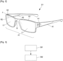
- the supplementary image is displayed using a wave guide encapsulated between two optical elements.
- the proximal surface PS and/or the distal surface DS is (are) curved surface(s); such a curved surface is for example a spherical surface, a toric surface, a sphero-toric surface; such a curved surface can also be an aspherized spherical or toric or sphero-toric surface.
- the proximal surface PS and/or the distal surface DS is (are) curved surface(s); such a curved surface is for example a spherical surface, a toric surface, a sphero-toric surface; such a curved surface can also be an aspherized spherical or toric or sphero-toric surface.
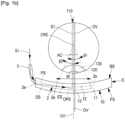
- the monobloc has a front surface FS and a back surface BS.
- the back surface BS is the surface of the monobloc the closest to the eye of the wearer when the optical system 10 is worn.
- the front surface FS may be convex, and the back surface BS may be concave.
- An optical power of the optical system 10, for the see-through vision TV depends on respective curvatures of the surfaces FS and BS and the light refractive index of the material of the optical system 10.
- the edge of zone 2a is the contour of the supplementary image SI output by the wave guide 2.
- the supplementary image SI intercepts the proximal surface PS according to an exit surface ES.
- One names "opposite surface” OS the surface corresponding to the exit surface ES on the distal surface.
- the imaging part is substantially a rectangle whose width is W and whose height is H.
- the back optical element 12, the front optical element 13, the optical system 10 may have a power depending on the part of the element considered.
- Each of these elements may for example have a far vision part, an intermediate vision part and a near vision part all these parts having a different power.
- the far vision part is intended to be used by the wearer in far vision activities.
- the near vision part is intended to be used by the wearer in near vision activities.
- the intermediate vision part is intended to be used by the wearer in intermediate vision activities.
- the far vision part of an element is the part crossed by a gaze axis of the wearer when the wearer is in far vision activities.
- the near vision part of an element is the part crossed by a gaze axis of the wearer when the wearer is in near vision activities.
- the intermediate vision part of an element is the part crossed by a gaze axis of the wearer when the wearer is in intermediate vision activities.
- the near vision part and the far vision part of an optical element for example ophthalmic lenses
- the power map one may determine the far vision part by finding the part of the optical element with a power between the far vision mean sphere, and the far vision mean sphere plus 15% of the prescribed addition.
- the power map one may determine the near vision part by finding the part of the optical element with a power between the far vision mean sphere plus 85% of the prescribed addition, and the far vision mean sphere plus 100% of the prescribed addition.
- the intermediate vision part is located between the far vision part and the near vision part, for example at equidistance of the far vision part and the near vision part.
- Far vision activities are when one looks at objects when accommodation is not necessary; in theory, objects at infinity, but generally one considers that objects farther than 3 meters are seen using far vision.
- Near vision activities are when one looks at close objects, generally less than 0.5 meters, for example, when reading a book.
- Intermediate vision activities are when one looks at objects located between 0.5 meters and 5 meters.
- the power of the back optical element 12 is considered to determine the power of the optical system 10.
- the power of the back optical element 12 and the power of the front optical element 13 are considered to determine the power of the optical system 10.
- the power of the near vision part of the optical system 10 When considering the power of the near vision part of the optical system 10, the power of the near vision part of the back optical element 12 and possibly of the front optical element 13 are considered.
- the power of the intermediate vision part of the back optical element 12 and possibly of the front optical element 13 are considered.
- the power of the far vision part of the optical system 10 When considering the power of the far vision part of the optical system 10, the power of the far vision part of the back optical element 12 and possibly of the front optical element 13 are considered.
- a prescription generally comprise a power dedicated to the far vision and an addition dedicated to the near vision.
- the power of a far vision part of an optical element (for example the optical system 10) complying with a prescription may be obtained directly from the far vision part of the prescription.
- the power of a near vision of the optical element complying with the prescription may be obtained by adding the addition of the prescription to the power of the far vision part of the prescription.
- the figure 3 represents a first embodiment of a method for determining values of parameters of the optical system 10.
- the method of the figure 3 may be for example a computer implemented method.
- the method of the figure 3 may be implemented in a computer comprising a memory and a processor.
- processors include microprocessors, microcontrollers, graphics processing units (GPUs), central processing units (CPUs), application processors, digital signal processors (DSPs), reduced instruction set computing (RISC) processors, systems on a chip (SoC), baseband processors, field-programmable gate arrays (FPGAs), programmable logic devices (PLDs), state machines, gated logic, discrete hardware circuits, and other suitable hardware configured to perform the various functionality described throughout this disclosure.
- GPUs graphics processing units
- CPUs central processing units
- DSPs digital signal processors
- RISC reduced instruction set computing
- SoC systems on a chip
- SoC systems on a chip
- FPGAs field-programmable gate arrays
- PLDs programmable logic devices
- state machines gated logic, discrete hardware circuits, and other suitable hardware configured to perform the various functionality described throughout this disclosure.
- the memory may be computer-readable media.
- such computer-readable media may include a random-access memory (RAM), a read-only memory (ROM), an electrically erasable programmable ROM (EEPROM), optical disk storage, magnetic disk storage, other magnetic storage devices, combinations of the aforementioned types of computer-readable media, or any other medium that may be used to store computer executable code in the form of instructions or data structures that may be accessed by the processor of the computer.
- the method for determining values of parameters of the optical system 10 may comprise, in a first embodiment:
- the method of the figure 3 has the advantage of using a front optical element 13 that is selected among a limited number of types and can be produced by mass-production techniques for cost efficiency.
- the back optical element 12 may be specific to each wearer and may be custom-made. If the front optical element 13 is common to all prescriptions and located at a fixed position in the frame (regardless of the fitting position of wearer), then the front optical element 13 may potentially introduce prismatic effects or aberrations in see-through vision TV.
- the back optical element 12 may be optimized to cancel or minimize these prismatic effects or aberrations, taking into account the actual half pupillary distance and fitting height of the wearer.
- a front optical element 13 that can be mass produced, from a set of limited number of front optical elements having different additions, and a limited power (between 0 and 2 dioptres).
- the power of the front optical element 13 must not be above a certain level. Indeed, a high power of front optical element 13 implies a back optical element with a negative power with high absolute value, and therefore the wearer has to accommodate to focus on the supplementary image.
- the back optical element 12 may advantageously be an individualized lens (for example of free form type), having power variations in a limited range.
- the back optical element 12 will affect the way the supplementary image is seen.
- the combination of the front optical element 13 and the back optical element 12 will affect the see-through vision TV.
- step 301 of selecting the front optical element 13 may be realized also based on half pupillary distance of the wearer.
- step 301 of selecting the front optical element 13 may be realized also based on a fitting height of the wearer.
- the parameters of the back optical element 12 may be an optical power value, astigmatism values, optical distortion values.
- the values of these parameters may depend on the part of the back optical element 12 that is considered.
- the black optical element 12 may comprise a far vision part and a near vision part and the values of the parameters may be different depending on which of the two parts is considered.
- parameters of the back optical element 12 may comprise:
- the pre-established front optical elements may have all, in a far vision part, a power of less than 1.5 diopter, for example less than 1 diopter.
- the step 301 of selecting the front optical element 13 among a set comprising a maximum of 6 pre-established front optical elements and the step 302 of determining values of parameters of the back optical element 12 based on an intended power map of the optical system 10 and the selected front optical element may be realized by:
- the method of the figure 3 may also comprise a step of determining a power for a part of the back optical element 12 by subtracting a power of a corresponding part of the front optical element 13 to a power of a corresponding part of the intended power map.
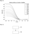
- the figure 5 represents another embodiment of the method for determining the values of the parameters of the optical system 10.
- a back optical element 12 being of regressive type, one means a back optical element 12 with a power of a far vision part that is higher than a power of near vision part.
- Having a back optical element 12 being of regressive type allows respecting the natural accommodation behavior when looking from the top to the bottom of the supplementary image. Wearers are used to increase their accommodation when looking from top to bottom in a real-life scene. Indeed, the power of the back optical element 12 decreases as gaze lowering increases, then the wearer has to increase his accommodation when gazing down, which is a natural accommodation behavior.
- the front optical element 13 and the back optical element are designed so that a combination of the front optical element 13 and back optical element 12 provides variable (PAL/Antifatigue) or constant (SV) power adapted for see-through vision TV.
- This power should satisfy the prescribed powers for far vision and near vision.
- the global power depends on the eye gaze vertical direction ( ⁇ ) and related world side distance Dist( ⁇ ). As a consequence, real objects located in the line of sight with the corresponding world side distance will be virtual located at a new distance Dseethrough( ⁇ ).
- This global power is defined according to the wearer prescription, typically provides far vision correction for straight away gaze direction, and near vision correction for lowered gaze direction, with intermediate values in between. It can be prescription for presbyopic, non-presbyopic (antifatigue with small amount of addition), or even emmetropes.
- the back optical element 12 may be designed to provide power to the supplementary image, during supplementary vision SV, so that the new distance (distance modified by the back optical element 12) is such that Dvirtual( ⁇ ) is same, or smaller than Dseethrough( ⁇ ).
- the apparent proximity (inverse of distance, in D) is less that then the maximal accommodation power of the wearer. Conversely, the apparent distance must be larger than the punctum remotum of the wearer.'.
- Dvirtual( ⁇ ) may be configured so that it decreases with ⁇ . Such that the wearer accommodates progressively when gazing from the top to the bottom of the supplementary image.
- the following examples and method propose different design for back and front optical elements, starting with back optical element 12 to then determine front optical element 13.
- Other alternatives are possible, for instance using not fully customized front optical element 13, but using the set of the pre-established front optical elements having different near vision power and far vision power and selecting the front optical element among this set.
- the near vision power and the far vision power may be also expressed as a couple power for far vision and addition.
- the addition is to be added at the power for far vision, to obtain the power of the near vision.
- one may select the pre-established front optical element, having the closer property - addition for instance - vs the calculated property for the front optical element 13 according to the method described below.
- the method is based on design conditions that can be expressed analytically using the following variables:
- the total power is the sum of the front power and back power:
- the back optical element 12 provides power such that the virtual image appears closer than the see-through image, one may consider that in far vision:
- the method of the figure 5 when assuming the wearer is emmetropic (otherwise adding to the back optical element 12 the far vision prescription), comprises:
- the determination of the values of the parameters of the first part of the front optical element 13 and the second part of the front optical 13 element is carried out by selecting the front optical element 13 among the set, introduced in the first embodiment of the method for determining the values of the parameters of the optical system 10 and comprising a maximum of 6 pre-established front optical elements.
- the back optical element 12 may be manufactured, by selecting a semifinished lens with an adapted front surface and by using digital surfacing of the back surface of the semifinished lens according to the values of the parameters of the back optical element 12.
- the front optical element 13 may also be manufactured the same way or may be selected from the set of the pre-established front optical elements. Alternatively, one may use set of mass prod lenses, using power step of 0.25D, and edging the lenses to the final frame shape to obtain the front optical element 13.
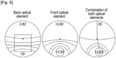
- the back optical element 12 one may consider one optical element with the surface facing the wave guide 2 being flat, while the other surface is shaped to provide the power. For far vision the back optical element 12 could provide zero power or a small amount of negative power (>-1.2D):
- the back optical element 12 provides a slightly negative power (for instance - 0.8D), the supplementary image will be seen closer than surrounding elements, here:
- the power of the near vision part of the back optical element 12 may be selected based on the prescription of the wearer. If the prescribed addition of the wearer is +1.5D, with near vision gaze angle ⁇ about 30°, one has:
- a front surface being flat and a back surface being curved.
- the power provided by the front optical element 13 needs to be selected so that combined front optical element 12 and back optical element 13 power provide zero power:
- a front optical element 13 with a power of the front surface varying from +0.8D to 2.5D.
- Dvirtual( ⁇ NV) being closer than infinity, at minimum same at same distance as far vision, or closer (1m for instance).
- the wearer will once again perceive the supplementary image closer, and may use remaining accommodation or depth of focus, in an extended way compared to far vision.
- This configuration is interesting since one provides low addition on back optical element (so low distortion of the supplementary image distortion, and a large field of view), while still having supplementary image being closer in near vision than in far vision.
- a soft progressive design would be possible since negative addition is low, aberration would be low. This can be beneficial for supplementary image with large field of view (20° to 50°).
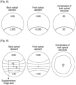
- Figure 6 represents, for the second example, the power map of the back optical element 12, the front optical element 13 and the combination of the back optical element 12 and the front optical element 13.
- Figure 9 represents, for the sixth example, the power map of the back optical element 12, the front optical element 13 and the combination of the back optical element 12 and the front optical element 13.
Landscapes
- Physics & Mathematics (AREA)
- Health & Medical Sciences (AREA)
- Ophthalmology & Optometry (AREA)
- General Physics & Mathematics (AREA)
- Optics & Photonics (AREA)
- General Health & Medical Sciences (AREA)
- Chemical & Material Sciences (AREA)
- Analytical Chemistry (AREA)
- Eyeglasses (AREA)
Priority Applications (2)
| Application Number | Priority Date | Filing Date | Title |
|---|---|---|---|
| EP23307280.0A EP4575448A1 (de) | 2023-12-20 | 2023-12-20 | Verfahren zur bestimmung von parameterwerten eines optischen systems |
| PCT/EP2024/086903 WO2025132434A1 (en) | 2023-12-20 | 2024-12-17 | Method for determining values of parameters of an optical system |
Applications Claiming Priority (1)
| Application Number | Priority Date | Filing Date | Title |
|---|---|---|---|
| EP23307280.0A EP4575448A1 (de) | 2023-12-20 | 2023-12-20 | Verfahren zur bestimmung von parameterwerten eines optischen systems |
Publications (1)
| Publication Number | Publication Date |
|---|---|
| EP4575448A1 true EP4575448A1 (de) | 2025-06-25 |
Family
ID=89573934
Family Applications (1)
| Application Number | Title | Priority Date | Filing Date |
|---|---|---|---|
| EP23307280.0A Pending EP4575448A1 (de) | 2023-12-20 | 2023-12-20 | Verfahren zur bestimmung von parameterwerten eines optischen systems |
Country Status (2)
| Country | Link |
|---|---|
| EP (1) | EP4575448A1 (de) |
| WO (1) | WO2025132434A1 (de) |
Citations (4)
| Publication number | Priority date | Publication date | Assignee | Title |
|---|---|---|---|---|
| WO2001095027A3 (en) | 2000-06-05 | 2002-08-15 | Lumus Ltd | Substrate-guided optical beam expander |
| WO2005024491A1 (en) | 2003-09-10 | 2005-03-17 | Lumus Ltd. | Substrate-guided optical devices |
| US11150476B2 (en) * | 2016-07-12 | 2021-10-19 | Essilor International | Method for providing a display unit for an electronic information device |
| US20220244542A1 (en) * | 2019-06-21 | 2022-08-04 | Essilor International | Set of semi-finished lenses with holographic components |
-
2023
- 2023-12-20 EP EP23307280.0A patent/EP4575448A1/de active Pending
-
2024
- 2024-12-17 WO PCT/EP2024/086903 patent/WO2025132434A1/en active Pending
Patent Citations (4)
| Publication number | Priority date | Publication date | Assignee | Title |
|---|---|---|---|---|
| WO2001095027A3 (en) | 2000-06-05 | 2002-08-15 | Lumus Ltd | Substrate-guided optical beam expander |
| WO2005024491A1 (en) | 2003-09-10 | 2005-03-17 | Lumus Ltd. | Substrate-guided optical devices |
| US11150476B2 (en) * | 2016-07-12 | 2021-10-19 | Essilor International | Method for providing a display unit for an electronic information device |
| US20220244542A1 (en) * | 2019-06-21 | 2022-08-04 | Essilor International | Set of semi-finished lenses with holographic components |
Non-Patent Citations (1)
| Title |
|---|
| PASCAL ALLIONEFRANCOISE AHSBAHSGILLES LE SAUX: "Application of optimization in computer-aided ophthalmic lens design", PROC. SPIE 3737, DESIGN AND ENGINEERING OF OPTICAL SYSTEMS II, 27 August 1999 (1999-08-27), Retrieved from the Internet <URL:https://doi.org/10.1117/12.360002> |
Also Published As
| Publication number | Publication date |
|---|---|
| WO2025132434A1 (en) | 2025-06-26 |
Similar Documents
| Publication | Publication Date | Title |
|---|---|---|
| US10509235B2 (en) | Method of calculating optical characteristics of an optical system according to a given spectacle frame | |
| US9791718B2 (en) | Progressive multifocal ophthalmic lens designed to inhibit progressive myopia of the wearer | |
| EP3241064B1 (de) | Brillenglas mit temporaler progressiver addition | |
| US10126568B2 (en) | Multifocal ophthalmic spectacle lens arranged to output a supplementary image | |
| US10247962B2 (en) | Method of calculating an optical system of a progressive addition ophthalmic lens being arranged to output a supplementary image | |
| US9547183B2 (en) | Method for determining an ophthalmic lens | |
| US9523864B2 (en) | Method for determining a progressive ophthalmic lens | |
| KR102522847B1 (ko) | 단초점 안구 렌즈를 결정하기 위한 방법 | |
| CN107567595B (zh) | 用于修改光学系统的非屈光参数的方法 | |
| US20150331254A1 (en) | Multifocal ophthalmic lens | |
| US8757799B2 (en) | Progressive multifocal ophthalmic lens | |
| EP4575448A1 (de) | Verfahren zur bestimmung von parameterwerten eines optischen systems | |
| EP4575449A1 (de) | Verfahren zur bestimmung von parameterwerten eines optischen systems | |
| EP4639269A1 (de) | Prismenmikrolinsen auf pal für korrekturbeitrag |
Legal Events
| Date | Code | Title | Description |
|---|---|---|---|
| PUAI | Public reference made under article 153(3) epc to a published international application that has entered the european phase |
Free format text: ORIGINAL CODE: 0009012 |
|
| STAA | Information on the status of an ep patent application or granted ep patent |
Free format text: STATUS: THE APPLICATION HAS BEEN PUBLISHED |
|
| AK | Designated contracting states |
Kind code of ref document: A1 Designated state(s): AL AT BE BG CH CY CZ DE DK EE ES FI FR GB GR HR HU IE IS IT LI LT LU LV MC ME MK MT NL NO PL PT RO RS SE SI SK SM TR |