EP4575480A1 - Lance de prélèvement pour prélever un détergent liquide d'un réservoir de détergent et procédé de fonctionnement d'une lance de soutirage - Google Patents
Lance de prélèvement pour prélever un détergent liquide d'un réservoir de détergent et procédé de fonctionnement d'une lance de soutirage Download PDFInfo
- Publication number
- EP4575480A1 EP4575480A1 EP24214684.3A EP24214684A EP4575480A1 EP 4575480 A1 EP4575480 A1 EP 4575480A1 EP 24214684 A EP24214684 A EP 24214684A EP 4575480 A1 EP4575480 A1 EP 4575480A1
- Authority
- EP
- European Patent Office
- Prior art keywords
- lance
- coil
- cleaning agent
- cleaning
- extraction
- Prior art date
- Legal status (The legal status is an assumption and is not a legal conclusion. Google has not performed a legal analysis and makes no representation as to the accuracy of the status listed.)
- Pending
Links
Images


Classifications
-
- G—PHYSICS
- G01—MEASURING; TESTING
- G01N—INVESTIGATING OR ANALYSING MATERIALS BY DETERMINING THEIR CHEMICAL OR PHYSICAL PROPERTIES
- G01N27/00—Investigating or analysing materials by the use of electric, electrochemical, or magnetic means
- G01N27/02—Investigating or analysing materials by the use of electric, electrochemical, or magnetic means by investigating impedance
- G01N27/023—Investigating or analysing materials by the use of electric, electrochemical, or magnetic means by investigating impedance where the material is placed in the field of a coil
- G01N27/025—Investigating or analysing materials by the use of electric, electrochemical, or magnetic means by investigating impedance where the material is placed in the field of a coil a current being generated within the material by induction
Definitions
- the invention relates to a withdrawal lance for withdrawing liquid cleaning agent from a cleaning agent container and a method for operating a withdrawal lance.
- cleaning agent is often drawn directly from a canister or container to minimize manual intervention for the operator. This can be achieved by integrating conductivity probes near the liquid dosing pumps or directly into the water-using machine, such as a washing machine or dishwasher, as a cleaning device. Measurements are mostly taken during the active cleaning program and, for example, at elevated temperatures.
- the above-mentioned probes are typically used in stainless steel pipes to test product quality during ongoing production, such as in ultrafiltration or chromatography. Furthermore, such measurements can be used to monitor cleaning-in-place (CIP) processes.
- CIP cleaning-in-place
- the probe would have to be removed from the machine, for example, once a month, or alternatively, a larger amount of the corresponding calibration fluid would have to be introduced into the machine, which entails enormous effort.
- the liquid chemicals or the cleaning agent used are sometimes diluted, for example, to dilute them or to utilize any remaining residues.
- the machine manufacturer is often contacted, even though the problem is due to incorrect dosage of the chemicals.
- the approach presented here aims to create an improved sampling lance, an improved method for operating the sampling lance and an improved control unit.
- this object is achieved by a sampling lance, a method for operating the sampling lance, and a control unit having the features of the main claims.
- the first coil and the second coil can be electrically isolated from one another or controlled separately, and their signals can be evaluated.
- the first coil can be designed to transmit a magnetic field into the receiving space into which, for example, cleaning agents are introduced.
- the second coil should be arranged or aligned in such a way that a magnetic field can be censored that forms in the receiving space or that is caused by a magnetization or polarization of parts of the cleaning agent in the receiving space.
- the first and second coils are arranged at a free, i.e. outer, end of the extraction lance, which advantageously also has a receiving opening or suction opening for the cleaning agent.
- the approach presented here is based on the realization that, by using the first coil and the second coil, a very efficient sensing or detection of cleaning agent parameters can be carried out, for example, to detect the actual presence of the cleaning agent at the sampling lance or to use this cleaning agent parameter to determine which cleaning agent is present and which one should be picked up by the sampling lance.
- insulation or encasing of the first and/or second coil can be specifically enabled, which makes damage to these coils more difficult. or prevented, without having to fear restrictions for the physical measuring method chosen here. While it is generally attempted to have no other substances that are not the medium to be measured within a radius of a few centimeters around the measuring probe, in this invention the influence can be minimized and even compensated.
- the canister with suction lance system can be described as a non-dynamic system, similar to how it is done, for example, with the cell constant.
- the influence on the measurement by the canister which is usually made of polypropylene (PP) and the suction lance, which can be made of, for example, polytetrafluoroethylene (PTFE) or polyvinyl chloride (PVC), can be quantified in order to compensate the measurement results and guarantee the accuracy of the measurement.
- PP polypropylene
- PTFE polytetrafluoroethylene
- PVC polyvinyl chloride
- a coil axis of the first and/or second coil is aligned substantially longitudinally to a direction of withdrawal of cleaning agent by means of the withdrawal lance.
- a coil axis can be understood to be an axis that is aligned substantially normal to the winding direction or winding plane.
- a direction of withdrawal of cleaning agent by the withdrawal lance can be understood, for example, to be the direction in which the cleaning agent is taken up from the cleaning agent container and/or passed on by the withdrawal lance.
- Such an embodiment of the approach proposed here offers the advantage of obtaining sufficiently reliable measurement results due to the alignment of the coils when the withdrawal lance is immersed in a cleaning agent container filled with very little cleaning agent, even if only a small proportion of cleaning agent reaches into the receiving space or interacts there with a corresponding induced magnetic field.
- first and/or second coil is aligned such that a coil axis of the first and/or second coil is aligned substantially transversely to a direction of withdrawal of cleaning agent by means of the withdrawal lance.
- Such an embodiment offers the advantage of being able to measure a parameter of the cleaning agent particularly precisely.
- such an arrangement of the coils requires only a very small installation space, so that the withdrawal lance can be kept as small as possible.
- the first and second coils can be arranged in a fluid-tight housing and/or protected in a fluid-tight manner against environmental influences.
- Such an embodiment offers the advantage of minimizing the risk of damage to the coils caused by aggressive substances or mechanical influences from outside the sampling lance.
- Another advantageous embodiment of the approach proposed here is one in which the first and/or second coil are arranged in a coil chamber, in particular one which is separated from a receiving opening for cleaning agent by at least one wall.
- Such an embodiment of the approach proposed here offers the advantage of maintaining a protected measuring area in which the cleaning agent can collect through the coil chamber.
- the corresponding wall can also prevent changes in the fill level from being detected by the suction of the cleaning agent, which changes are solely due to the removal of the cleaning agent and could therefore provide an erroneous parameter for the cleaning agent if detected accordingly.
- a particularly advantageous embodiment of the approach proposed here is one in which at least one coil chamber opening is provided in the coil chamber for venting the coil chamber.
- Such an embodiment offers the advantage of being able to release any air cushion that may arise from the coil chamber when inserting the sampling lance into the cleaning container, thus enabling a precise measurement of a parameter of the cleaning agent.
- the sampling lance can also further comprise a float switch, in particular wherein the float switch is arranged in a float switch chamber and/or at least one float switch opening is provided for venting the float switch chamber.
- a float switch in particular wherein the float switch is arranged in a float switch chamber and/or at least one float switch opening is provided for venting the float switch chamber.
- the approach presented here further provides a control unit which is designed to carry out the steps of a variant of a method presented here in corresponding devices to carry out, control, or implement.
- This embodiment of the invention in the form of a device also allows the problem underlying the invention to be solved quickly and efficiently.
- the control unit can be designed to read in input signals and to determine and provide output signals using the input signals.
- An input signal can, for example, represent a sensor signal that can be read in via an input interface of the control unit.
- An output signal can represent a control signal or a data signal that can be provided at an output interface of the control unit.
- the control unit can be designed to determine the output signals using a processing rule implemented in hardware or software.
- the control unit can comprise a logic circuit, an integrated circuit, or a software module and can, for example, be implemented as a discrete component or be comprised of a discrete component.
- a computer program product or computer program with program code that can be stored on a machine-readable carrier or storage medium such as a semiconductor memory, a hard disk memory, or an optical memory. If the program product or program is executed on a computer or a control unit, the program product or program can be used to carry out, implement, and/or control the steps of the method according to one of the embodiments described here.
- the approach described is based on a professional device, for example a medical device such as a cleaning or disinfection device, a small sterilizer, a large-capacity disinfector or a container washing system, the approach described here can also be used accordingly in connection with a household appliance.
- a professional device for example a medical device such as a cleaning or disinfection device, a small sterilizer, a large-capacity disinfector or a container washing system
- the approach described here can also be used accordingly in connection with a household appliance.
- Figure 2 shows a side section view of the Figure 1 illustrated embodiment of the sampling lance 100.
- the first coil 120 and the second coil 125 are shown, but they are located one above the other and thus at least partially hidden.
- the first coil 120 and the second coil 120 are also aligned along the hollow axis 130, which is aligned transversely to the direction of removal of the cleaning agent by the extraction lance 100, wherein this direction of removal points upwards in this case in order to guide the cleaning agent from the extraction lance 100 to a cleaning device 200 so that it can be used there in a cleaning process.
- the cleaning device 200 comprises a control unit 210 designed to operate the extraction lance 100.
- the control unit 210 comprises a unit 215 for applying an output voltage signal 220 to the first coil 120 of the extraction lance 100 so that a magnetic field can be formed in the receiving chamber or the coil chamber 110 by the first coil 120. Furthermore, the control unit 210 comprises a receiving unit 225 configured to receive a received voltage signal 230 from the second coil 125. The received voltage signal 230 can then be evaluated in an evaluation unit 235 to determine a parameter 240 of the cleaning fluid 245 in the cleaning agent 250 into which the sampling lance 100 was immersed.
- This parameter 240 can be determined, for example, in the evaluation unit 135 with the aid of a reference parameter 255 which is loaded from a memory 260, wherein this reference parameter 255 corresponds, for example, to a parameter of a known cleaning fluid 245 and thus, if the parameter 240 determined from the received voltage signal 230 matches (for example within a tolerance range of ten percent), it can be recognized that the cleaning fluid or the cleaning agent 245 corresponds to the cleaning agent whose assigned reference parameter 255 was retrieved from the memory 260.
- the first coil 120 and the second coil 125 are surrounded by a sheath 265 or an insulation layer, which shields the first coil 120 and the second coil 125 in a fluid-tight manner from an external environment of the sampling lance 100.
- Figure 3 shows another side sectional view of the sampling lance 100 from the Figure 1 or 2 , wherein it can now be seen that the first coil 120 and the second coil 125 are arranged next to one another or one behind the other on the same hollow axis 130, wherein this axis 130 is aligned substantially perpendicular or transverse to the removal direction of the cleaning agent.
- Figure 4 shows a schematic representation from below of two further embodiments of a sampling lance 100.
- the coils 120 and 125 are now aligned such that the axis 130 extends through the two coils 100 2020 along the direction of pickup of the cleaning agent, namely here into the plane of the drawing.
- This can be the upper illustration of an embodiment of the sampling lance 100 as well as from the lower illustration of one of the sampling lance 100 from the Figure 4
- Figure 4 an alternative division of the coil chamber 110, the float switch chamber 155 and the corresponding wall 115 can also be seen.
- Figure 5 shows a side section view of the Figure 4 illustrated embodiment of the extraction lance 100.
- the first coil 120 which acts, for example, as a transmitting coil
- the second coil 125 which acts as a receiving coil
- the first coil 120 and the second coil 125 are aligned parallel to a free end of the extraction lance 100, via which cleaning agent can be taken up from the cleaning agent container.
- FIG. 6 shows a sectional view through a further embodiment of the sampling lance 100.
- an inductive conductivity sensor in the form of the two coils 120 and 125 (which correspond to the Figure 6 shown structure are arranged one behind the other) are arranged around a suction hose 600, so that this hose 600 forms the receiving chamber or coil chamber 110.
- a contact sensor 605 for example a platinum pin or plate, can also be provided in order to output a signal upon contact of this contact sensor 605 that a liquid is actually flowing in the hose 600 and a corresponding control of the coils 120 and 125 can take place.
- the coils 120 and 125 can then be supplied with a corresponding voltage or a corresponding voltage can be tapped at these coils in order to determine the parameter of the cleaning agent.
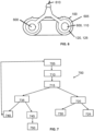
- Figure 7 shows a flowchart of an embodiment of the approach proposed here as a method 700 for operating a variant of a sampling lance presented here, wherein the method 700 comprises a step 705 of applying an output voltage signal to the first coil of the sampling lance to form the magnetic field. Furthermore, the method 700 comprises a step 710 of receiving a received voltage signal from the second coil and a step 715 of evaluating the received voltage signal to determine a parameter of the cleaning fluid.
- the parameter can, for example, be a conductivity of the cleaning agent currently present at the sampling lance 100. This parameter can be reused in different variants.
- this further use of the specific parameter can be carried out in such a way that the specific parameter is passed on to a machine intelligence of a cleaning device such as a washing machine/dishwasher (step 720), wherein, if the cleaning agent present can be identified, for example using the reference parameter, a dosage or a dosage profile for using the cleaning agent in a cleaning program currently being carried out is set in a further step 725. However, if the cleaning agent present is not recognized, a new profile for using the cleaning agent present in a cleaning program can be created in a further step 730.
- a machine intelligence of a cleaning device such as a washing machine/dishwasher
- the obtained parameter can also be passed on to a pump intelligence of a pump system for quality assurance monitoring (step 735). If the parameter lies within predefined specifications (step 740), the program can return and initiate a new execution of the process steps to perform cyclical monitoring of the parameter. However, if the pump intelligence determines in step 735 that the parameter lies outside the specified specifications (step 745), an error message can be output (step 750).
- the conductivity of the cleaning agent can be used as a specific parameter.
- Conductivity describes the ability of a conductive chemical substance or mixture of substances to conduct and transmit energy, such as electrical energy in the form of current, in a room.
- the inductive method can be used to apply and subsequently evaluate signals via two electromagnetic coils, with one coil acting as the transmitter and one as the receiver. These coils are usually protected from aggressive media by a plastic coating.
- the transmitting coil generates an alternating magnetic field, which induces an electrical voltage in the medium, which sets the ions in the liquid in motion, resulting in an alternating current.
- This alternating current generates an alternating magnetic field in the receiving coil.
- the conductivity is directly dependent on the formulation as well as the ion concentration used.
- the current generated in the winding of at least one of the coils is evaluated in a measuring transducer, and the value of the electrolytic conductivity is calculated.
- the conductivity can thus be used to uniquely determine the liquid chemical or the cleaning agent used, thus allowing tracking.
- the data on the applicant's cleaning agents are stored, for example, in a database or in the internal memory of the machine or the The measured conductivity can be matched or verified by comparison. This can also be used for quality assurance through continuous measurement.
- the crystallization of salts is a known stability problem in liquid cleaning chemicals. These crystallized salts can reduce the conductivity of the liquid. This can also increase the conductivity of liquids because the Coulomb force of the ions present is reduced.
- the Coulomb force is particularly crucial for measurements involving chemicals with a particularly high concentration of ions, as the Coulomb force inhibits the large number of ions from interacting with one another, thereby reducing the induced current flow. Therefore, an upper and lower limit can be defined for the specification.
- Conductivity can be measured amperometrically, potentiometrically, or conductively/inductively. Induction measurement is preferred for this application.
- Induction measurement is particularly preferred, as it can cover a range from 10-4 to 10° S/cm with an accuracy of less than ⁇ 1% and a reproducibility of ⁇ 0.5%. Expanding the data stored in the memory for detergents and cleaning products from other manufacturers is also conceivable. Two options for implementing the measurement are conceivable, both in professional laundry and dishwashing, and in household laundry care: Professional (dosing lances as extraction lance 100): A conductivity probe is already attached to the bottom of the dosing or withdrawal lance 100, which communicates with the machine 200 and/or other parts of the liquid dosing system. An advantage of this design is the existing wiring of the dosing lance 100 with the pump system for the use of a float switch for level detection.
- FIG. 1 is Figures 1 to 3
- the illustration in these figures shows a representation of a modified conventional, commercially available inductive conductivity probe, which is embedded within a conventional dosing lance 100.
- the sampling lance 100 shown here is replaced by an outlet to the pump with the float switch, which is normally located at the location of the electrode.
- indentations can be made in the edges of the dosing lance, which are not in the Figures 1 to 3 are not shown and which lead to a lateral inlet of the These serve to prevent the extraction lance 100 from becoming stuck to the bottom of the detergent container. These recesses allow chemicals or detergent to continue to be drawn even if the dosing lance rests directly on the bottom of the container. Furthermore, a vent is installed as standard for the same reason.
- the sampling lance 100 provides the Figures 4 and 5 represents a new approach as a replacement for the electrode.
- the design 1 shown here is a similar structure of the sampling lance 100 as in the Figures 1 to 3 visible, with the major difference that the electrode or coils 120, 125 are now aligned vertically instead of horizontally. The idea is that with this alignment, even deeper liquid levels can be depicted or measured with sufficient precision.
- Figure 4 In Design 2 a realignment of the chambers and areas of the sampling lance 100 can be seen to provide more space for the float switch. The media outlets and receiving openings are relocated to the sides or edges to create the necessary space.
- the design of the electrode and coils 120, 125 also allows for a reduction in the space required for the electrode.
- Household A conductivity probe is installed within the pump lines.
- One possible option would be to position it upstream of the platinum sensor within the household washing machine as a cleaning device. Positioning the sensors close to the chemicals is preferred, e.g., with the platinum sensor. This system can be understood as an extension of the platinum sensor, which already measures resistance to detect material flow. Positioning directly within the chemicals is particularly preferred, enabling identification before pumping. The availability of such a sensor solution makes such integration simple and accessible.
- the system underlying the approach presented here has the following logic: If the chemistry or the cleaning agent is known (i.e. the conductivity is matched with a detergent or cleaning agent in the stored database The dosing profile is automatically retrieved, for example, from the cloud (e.g., Miele MOVE) or locally. The user then has the option of setting parameters such as laundry soiling and water hardness to enable the ideal liquid dosing with just two clicks. Alternatively, the water hardness is already stored, so further settings are not necessary. The conductivity measurement can be performed before the start of each wash program. Furthermore, the system can enable easy assignment of programs and chemicals or cleaning agents.
- the known and measured-confirmed colored detergent should be selected as a preset. This can reduce workload for the user and the cleaning device's customer service. If the chemicals or cleaning agent are unknown, a new profile for the detergent or cleaning agent can be created, which the user can then configure. The profile can be saved locally or online (e.g., Miele MOVE).
- Figure 7 A flowchart of such a procedure is shown. The approach presented here is initially intended for integration into the applicant's cleaning appliances and cleaning products (Miele wash chemicals, both professional and household).
- the dosage data can also be used to expand a central database at the applicant's company. Furthermore, this data can be used for marketing and application technology.
- the risk of incorrect detergent dosage is greatly reduced when using the approach presented here, as continuous monitoring of the washing chemicals or cleaning agent is performed instead of only intermittently. This can prevent laundry damage by largely removing the human factor. Furthermore, reliable data can be obtained in the event of unsatisfactory wash results, and customer support can be improved by better quantifying and qualifying a source of error. Dilution of the washing chemicals or cleaning agent can be reliably tracked and verified.
Landscapes
- Chemical & Material Sciences (AREA)
- Chemical Kinetics & Catalysis (AREA)
- Electrochemistry (AREA)
- Physics & Mathematics (AREA)
- Health & Medical Sciences (AREA)
- Life Sciences & Earth Sciences (AREA)
- Analytical Chemistry (AREA)
- Biochemistry (AREA)
- General Health & Medical Sciences (AREA)
- General Physics & Mathematics (AREA)
- Immunology (AREA)
- Pathology (AREA)
- Investigating Or Analyzing Materials By The Use Of Electric Means (AREA)
Applications Claiming Priority (1)
| Application Number | Priority Date | Filing Date | Title |
|---|---|---|---|
| DE102023135913.4A DE102023135913A1 (de) | 2023-12-20 | 2023-12-20 | Entnahmelanze zur Entnahme von flüssigem Reinigungsmittel aus einem Reinigungsmittelbehälter und Verfahren zum Betreiben einer Entnahmelanze |
Publications (1)
| Publication Number | Publication Date |
|---|---|
| EP4575480A1 true EP4575480A1 (fr) | 2025-06-25 |
Family
ID=93647972
Family Applications (1)
| Application Number | Title | Priority Date | Filing Date |
|---|---|---|---|
| EP24214684.3A Pending EP4575480A1 (fr) | 2023-12-20 | 2024-11-22 | Lance de prélèvement pour prélever un détergent liquide d'un réservoir de détergent et procédé de fonctionnement d'une lance de soutirage |
Country Status (2)
| Country | Link |
|---|---|
| EP (1) | EP4575480A1 (fr) |
| DE (1) | DE102023135913A1 (fr) |
Citations (4)
| Publication number | Priority date | Publication date | Assignee | Title |
|---|---|---|---|---|
| EP0303222B1 (fr) * | 1987-08-12 | 1993-10-27 | Siemens Aktiengesellschaft | Capteur pour la mesure inductive de la conductivité dans les fluides |
| EP2241241A1 (fr) * | 2009-04-14 | 2010-10-20 | Chemische Fabrik Dr. Weigert GmbH & Co. KG | Dispositif d'extraction de liquide à partir d'un récipient |
| US20120326711A1 (en) * | 2010-02-06 | 2012-12-27 | Sgs Instruments Llc | Toroidal conductivity probe with integrated circuitry |
| EP3673106B1 (fr) * | 2017-08-24 | 2023-01-04 | Arçelik Anonim Sirketi | Machine à laver avec dispositif d'alimentation et de dosage d'agent de traitement amélioré |
Family Cites Families (4)
| Publication number | Priority date | Publication date | Assignee | Title |
|---|---|---|---|---|
| DE10009402A1 (de) * | 1999-02-28 | 2001-05-03 | Steag Micro Tech Gmbh | Verfahren zum Bestimmen von Eigenschaften eines Mediums |
| DE102009052029A1 (de) * | 2009-11-05 | 2011-05-26 | Meiko Maschinenbau Gmbh & Co. Kg | Sauglanze und Behälter mit Codiergeometrie |
| DE102018114909B4 (de) * | 2017-07-07 | 2024-04-04 | Miele & Cie. Kg | Verfahren zum Ermitteln einer Restzyklenzahl einer Reinigungsflüssigkeit in einem Vorratsbehälter eines maschinengesteuerten Reinigungs- oder Desinfektionsautomaten unter Verwendung einer Sauglanzeinheit |
| DE102019102033A1 (de) * | 2019-01-28 | 2020-07-30 | Miele & Cie. Kg | Sauglanze für die Entnahme von Flüssigkeit aus einem Behälter |
-
2023
- 2023-12-20 DE DE102023135913.4A patent/DE102023135913A1/de active Pending
-
2024
- 2024-11-22 EP EP24214684.3A patent/EP4575480A1/fr active Pending
Patent Citations (4)
| Publication number | Priority date | Publication date | Assignee | Title |
|---|---|---|---|---|
| EP0303222B1 (fr) * | 1987-08-12 | 1993-10-27 | Siemens Aktiengesellschaft | Capteur pour la mesure inductive de la conductivité dans les fluides |
| EP2241241A1 (fr) * | 2009-04-14 | 2010-10-20 | Chemische Fabrik Dr. Weigert GmbH & Co. KG | Dispositif d'extraction de liquide à partir d'un récipient |
| US20120326711A1 (en) * | 2010-02-06 | 2012-12-27 | Sgs Instruments Llc | Toroidal conductivity probe with integrated circuitry |
| EP3673106B1 (fr) * | 2017-08-24 | 2023-01-04 | Arçelik Anonim Sirketi | Machine à laver avec dispositif d'alimentation et de dosage d'agent de traitement amélioré |
Also Published As
| Publication number | Publication date |
|---|---|
| DE102023135913A1 (de) | 2025-06-26 |
Similar Documents
| Publication | Publication Date | Title |
|---|---|---|
| EP2533035B1 (fr) | Dispositif et procédé de détection des caractéristiques de matériaux | |
| EP2902774B1 (fr) | Procédé et dispositif d'enregistrement des propriétés de fluides aqueux par d'impédance spectroscopie | |
| WO2018015543A1 (fr) | Pointe de pipette destinée à un dispositif de pipetage automatique | |
| EP3452222A1 (fr) | Pointe de pipette destinée à un dispositif de pipetage automatique | |
| DE102016225833A1 (de) | Verfahren zur Dosierung von Reinigungsmitteln | |
| DE19650915B4 (de) | Flüssigkeitsführendes Hausgerät mit einer Programmsteuerung | |
| DE102012112784A1 (de) | Verfahren zur Bestimmung eines Zustands eines Sensors | |
| DE102016105839A1 (de) | Kalibriersystem | |
| EP3118628B1 (fr) | Procede de pipetage de liquides dans un appareil d'analyse automatique | |
| EP2711697A2 (fr) | Procédé et dispositif d'enregistrement des propriétés de fluides | |
| EP3268528B1 (fr) | Procédé pour faire fonctionner un lave-linge comprenant un capteur d'impédance et lave-linge pour la mise en oeuvre de ce procédé | |
| DE102019134611A1 (de) | Titrierapparat und Titrierverfahren | |
| DE102018125908A1 (de) | Verfahren zur Bestimmung einer Prozessgrößer mit einem Klassifikator zur Auswahl eines Messverfahrens | |
| DE102013104203B4 (de) | Verfahren und Vorrichtung zur Bestimmung einer Restbetriebsdauer eines Messaufnehmers | |
| DE102012004696B3 (de) | Verfahren und Vorrichtung zur Überprüfung von Reinigungs- und Desinfektionsgeräten | |
| WO2003075108A1 (fr) | Dispositif et procede de surveillance et de regulation d'une solution utilisee dans un processus | |
| EP2978362B1 (fr) | Procédé et système de surveillance d'un dispositif de traitement pour endoscopes | |
| EP4575480A1 (fr) | Lance de prélèvement pour prélever un détergent liquide d'un réservoir de détergent et procédé de fonctionnement d'une lance de soutirage | |
| DE69607693T2 (de) | Verfahren und Anordnung zum Abtasten der Qualitätsänderungen eines Harzbettes | |
| DE102012108739A1 (de) | Verfahren und Vorrichtung zur Bestimmung eines Zustands einer Messsonde | |
| DE102015016742B4 (de) | Verfahren zur Überprüfung der Reagierfähigkeit eines elektrischen und/oder elektronischen Sensors | |
| DE3712377C2 (fr) | ||
| EP3585930B1 (fr) | Appareil ménager à circulation d'eau et procédé pour faire fonctionner un appareil ménager à circulation d'eau | |
| DE102008040334B4 (de) | Verfahren zum Betreiben einer Geschirrspülmaschine, Überwachungseinrichtung für eine Spülflotte und Geschirrspülmaschine | |
| DE112007002990T5 (de) | Anordnung, Verfahren und Computerprogramm zum Testen von Melkmaschinen anhand des Vakuums im Betriebsmodus |
Legal Events
| Date | Code | Title | Description |
|---|---|---|---|
| PUAI | Public reference made under article 153(3) epc to a published international application that has entered the european phase |
Free format text: ORIGINAL CODE: 0009012 |
|
| STAA | Information on the status of an ep patent application or granted ep patent |
Free format text: STATUS: THE APPLICATION HAS BEEN PUBLISHED |
|
| AK | Designated contracting states |
Kind code of ref document: A1 Designated state(s): AL AT BE BG CH CY CZ DE DK EE ES FI FR GB GR HR HU IE IS IT LI LT LU LV MC ME MK MT NL NO PL PT RO RS SE SI SK SM TR |