EP4575538A1 - System und verfahren zur diagnose des verschlechterungszustands einer batterie - Google Patents
System und verfahren zur diagnose des verschlechterungszustands einer batterie Download PDFInfo
- Publication number
- EP4575538A1 EP4575538A1 EP23873201.0A EP23873201A EP4575538A1 EP 4575538 A1 EP4575538 A1 EP 4575538A1 EP 23873201 A EP23873201 A EP 23873201A EP 4575538 A1 EP4575538 A1 EP 4575538A1
- Authority
- EP
- European Patent Office
- Prior art keywords
- battery
- electrode
- side reaction
- state
- diagnosis apparatus
- Prior art date
- Legal status (The legal status is an assumption and is not a legal conclusion. Google has not performed a legal analysis and makes no representation as to the accuracy of the status listed.)
- Pending
Links
Images




Classifications
-
- G—PHYSICS
- G01—MEASURING; TESTING
- G01R—MEASURING ELECTRIC VARIABLES; MEASURING MAGNETIC VARIABLES
- G01R31/00—Arrangements for testing electric properties; Arrangements for locating electric faults; Arrangements for electrical testing characterised by what is being tested not provided for elsewhere
- G01R31/36—Arrangements for testing, measuring or monitoring the electrical condition of accumulators or electric batteries, e.g. capacity or state of charge [SoC]
- G01R31/367—Software therefor, e.g. for battery testing using modelling or look-up tables
-
- G—PHYSICS
- G01—MEASURING; TESTING
- G01R—MEASURING ELECTRIC VARIABLES; MEASURING MAGNETIC VARIABLES
- G01R31/00—Arrangements for testing electric properties; Arrangements for locating electric faults; Arrangements for electrical testing characterised by what is being tested not provided for elsewhere
- G01R31/36—Arrangements for testing, measuring or monitoring the electrical condition of accumulators or electric batteries, e.g. capacity or state of charge [SoC]
- G01R31/3644—Constructional arrangements
- G01R31/3648—Constructional arrangements comprising digital calculation means, e.g. for performing an algorithm
-
- G—PHYSICS
- G01—MEASURING; TESTING
- G01R—MEASURING ELECTRIC VARIABLES; MEASURING MAGNETIC VARIABLES
- G01R31/00—Arrangements for testing electric properties; Arrangements for locating electric faults; Arrangements for electrical testing characterised by what is being tested not provided for elsewhere
- G01R31/36—Arrangements for testing, measuring or monitoring the electrical condition of accumulators or electric batteries, e.g. capacity or state of charge [SoC]
- G01R31/378—Arrangements for testing, measuring or monitoring the electrical condition of accumulators or electric batteries, e.g. capacity or state of charge [SoC] specially adapted for the type of battery or accumulator
-
- G—PHYSICS
- G01—MEASURING; TESTING
- G01R—MEASURING ELECTRIC VARIABLES; MEASURING MAGNETIC VARIABLES
- G01R31/00—Arrangements for testing electric properties; Arrangements for locating electric faults; Arrangements for electrical testing characterised by what is being tested not provided for elsewhere
- G01R31/36—Arrangements for testing, measuring or monitoring the electrical condition of accumulators or electric batteries, e.g. capacity or state of charge [SoC]
- G01R31/385—Arrangements for measuring battery or accumulator variables
- G01R31/387—Determining ampere-hour charge capacity or SoC
- G01R31/388—Determining ampere-hour charge capacity or SoC involving voltage measurements
-
- G—PHYSICS
- G01—MEASURING; TESTING
- G01R—MEASURING ELECTRIC VARIABLES; MEASURING MAGNETIC VARIABLES
- G01R31/00—Arrangements for testing electric properties; Arrangements for locating electric faults; Arrangements for electrical testing characterised by what is being tested not provided for elsewhere
- G01R31/36—Arrangements for testing, measuring or monitoring the electrical condition of accumulators or electric batteries, e.g. capacity or state of charge [SoC]
- G01R31/392—Determining battery ageing or deterioration, e.g. state of health
-
- H—ELECTRICITY
- H01—ELECTRIC ELEMENTS
- H01M—PROCESSES OR MEANS, e.g. BATTERIES, FOR THE DIRECT CONVERSION OF CHEMICAL ENERGY INTO ELECTRICAL ENERGY
- H01M10/00—Secondary cells; Manufacture thereof
- H01M10/05—Accumulators with non-aqueous electrolyte
- H01M10/052—Li-accumulators
-
- H—ELECTRICITY
- H01—ELECTRIC ELEMENTS
- H01M—PROCESSES OR MEANS, e.g. BATTERIES, FOR THE DIRECT CONVERSION OF CHEMICAL ENERGY INTO ELECTRICAL ENERGY
- H01M10/00—Secondary cells; Manufacture thereof
- H01M10/05—Accumulators with non-aqueous electrolyte
- H01M10/052—Li-accumulators
- H01M10/0525—Rocking-chair batteries, i.e. batteries with lithium insertion or intercalation in both electrodes; Lithium-ion batteries
-
- H—ELECTRICITY
- H01—ELECTRIC ELEMENTS
- H01M—PROCESSES OR MEANS, e.g. BATTERIES, FOR THE DIRECT CONVERSION OF CHEMICAL ENERGY INTO ELECTRICAL ENERGY
- H01M10/00—Secondary cells; Manufacture thereof
- H01M10/42—Methods or arrangements for servicing or maintenance of secondary cells or secondary half-cells
- H01M10/425—Structural combination with electronic components, e.g. electronic circuits integrated to the outside of the casing
-
- H—ELECTRICITY
- H01—ELECTRIC ELEMENTS
- H01M—PROCESSES OR MEANS, e.g. BATTERIES, FOR THE DIRECT CONVERSION OF CHEMICAL ENERGY INTO ELECTRICAL ENERGY
- H01M10/00—Secondary cells; Manufacture thereof
- H01M10/42—Methods or arrangements for servicing or maintenance of secondary cells or secondary half-cells
- H01M10/48—Accumulators combined with arrangements for measuring, testing or indicating the condition of cells, e.g. the level or density of the electrolyte
-
- G—PHYSICS
- G01—MEASURING; TESTING
- G01R—MEASURING ELECTRIC VARIABLES; MEASURING MAGNETIC VARIABLES
- G01R31/00—Arrangements for testing electric properties; Arrangements for locating electric faults; Arrangements for electrical testing characterised by what is being tested not provided for elsewhere
- G01R31/36—Arrangements for testing, measuring or monitoring the electrical condition of accumulators or electric batteries, e.g. capacity or state of charge [SoC]
- G01R31/3644—Constructional arrangements
- G01R31/3646—Constructional arrangements for indicating electrical conditions or variables, e.g. visual or audible indicators
-
- G—PHYSICS
- G01—MEASURING; TESTING
- G01R—MEASURING ELECTRIC VARIABLES; MEASURING MAGNETIC VARIABLES
- G01R31/00—Arrangements for testing electric properties; Arrangements for locating electric faults; Arrangements for electrical testing characterised by what is being tested not provided for elsewhere
- G01R31/36—Arrangements for testing, measuring or monitoring the electrical condition of accumulators or electric batteries, e.g. capacity or state of charge [SoC]
- G01R31/382—Arrangements for monitoring battery or accumulator variables, e.g. SoC
- G01R31/3828—Arrangements for monitoring battery or accumulator variables, e.g. SoC using current integration
- G01R31/3832—Arrangements for monitoring battery or accumulator variables, e.g. SoC using current integration without measurement of battery voltage
-
- G—PHYSICS
- G01—MEASURING; TESTING
- G01R—MEASURING ELECTRIC VARIABLES; MEASURING MAGNETIC VARIABLES
- G01R31/00—Arrangements for testing electric properties; Arrangements for locating electric faults; Arrangements for electrical testing characterised by what is being tested not provided for elsewhere
- G01R31/36—Arrangements for testing, measuring or monitoring the electrical condition of accumulators or electric batteries, e.g. capacity or state of charge [SoC]
- G01R31/382—Arrangements for monitoring battery or accumulator variables, e.g. SoC
- G01R31/3835—Arrangements for monitoring battery or accumulator variables, e.g. SoC involving only voltage measurements
-
- G—PHYSICS
- G01—MEASURING; TESTING
- G01R—MEASURING ELECTRIC VARIABLES; MEASURING MAGNETIC VARIABLES
- G01R31/00—Arrangements for testing electric properties; Arrangements for locating electric faults; Arrangements for electrical testing characterised by what is being tested not provided for elsewhere
- G01R31/36—Arrangements for testing, measuring or monitoring the electrical condition of accumulators or electric batteries, e.g. capacity or state of charge [SoC]
- G01R31/382—Arrangements for monitoring battery or accumulator variables, e.g. SoC
- G01R31/3842—Arrangements for monitoring battery or accumulator variables, e.g. SoC combining voltage and current measurements
-
- H—ELECTRICITY
- H01—ELECTRIC ELEMENTS
- H01M—PROCESSES OR MEANS, e.g. BATTERIES, FOR THE DIRECT CONVERSION OF CHEMICAL ENERGY INTO ELECTRICAL ENERGY
- H01M10/00—Secondary cells; Manufacture thereof
- H01M10/42—Methods or arrangements for servicing or maintenance of secondary cells or secondary half-cells
- H01M10/425—Structural combination with electronic components, e.g. electronic circuits integrated to the outside of the casing
- H01M2010/4271—Battery management systems including electronic circuits, e.g. control of current or voltage to keep battery in healthy state, cell balancing
-
- Y—GENERAL TAGGING OF NEW TECHNOLOGICAL DEVELOPMENTS; GENERAL TAGGING OF CROSS-SECTIONAL TECHNOLOGIES SPANNING OVER SEVERAL SECTIONS OF THE IPC; TECHNICAL SUBJECTS COVERED BY FORMER USPC CROSS-REFERENCE ART COLLECTIONS [XRACs] AND DIGESTS
- Y02—TECHNOLOGIES OR APPLICATIONS FOR MITIGATION OR ADAPTATION AGAINST CLIMATE CHANGE
- Y02E—REDUCTION OF GREENHOUSE GAS [GHG] EMISSIONS, RELATED TO ENERGY GENERATION, TRANSMISSION OR DISTRIBUTION
- Y02E60/00—Enabling technologies; Technologies with a potential or indirect contribution to GHG emissions mitigation
- Y02E60/10—Energy storage using batteries
Definitions
- the present disclosure relates to a system and method for diagnosing a degradation state of a battery, and more particularly, to a system and method for improving the performance of diagnosing the degradation state.
- an electric vehicle or a hybrid electric vehicle uses electric energy stored in a battery as an energy source.
- a battery for example, lithium-ion polymer batteries are widely used as batteries for electric vehicles, and research on the batteries are being actively performed.
- the electric vehicle or the hybrid electric vehicle is driven by energy charged in the battery, it is important to not only diagnose (or predict) the current state of the battery, but also a degradation state of the battery.
- a battery capacity may be reduced by a side reaction, such as solid electrolyte interphase film formation, and the side reaction may be considered to diagnose the degradation state of the battery.
- a side reaction state of an electrode may be predicted and the degradation state of the battery may be diagnosed based on a result of the prediction.
- physics-based models such as a Doyle Fuller Newman (DFN) model, a single particle model (SPM), an enhanced single particle model (ESPM), etc., may be used to diagnose the degradation state of the battery.
- DNN Doyle Fuller Newman
- SPM single particle model
- EPM enhanced single particle model
- physics-based models are models that formalize the physical movement of particles inside the battery using complex differential equations, and the degradation state of the battery may be diagnosed relatively accurately, but computational complexity is high due to mathematical complexity.
- At least one of various embodiments of the present disclosure aim to provide a system and method for diagnosing a degradation state of a battery to improve the performance of diagnosing the degradation state.
- At least one of various embodiments of the present disclosure aim to provide a system and method for diagnosing a degradation state of a battery to predict a side reaction state based on an equilibrium potential of an electrode.
- At least one of various embodiments of the present disclosure aim to provide a system and method for diagnosing a degradation state of a battery to predict a side reaction state using an open circuit voltage (OCV) model having a lower mathematical complexity than a physics-based model.
- OCV open circuit voltage
- a diagnosis system for diagnosing a state of a battery includes the battery and a diagnosis apparatus configured to diagnose the state of the battery, in which the diagnosis apparatus is further configured to predict a side reaction rate of an electrode, based on an open circuit voltage (OCV) model defined with a state of charge (SOC) of the battery and an accumulative side reaction amount of the electrode and predict a degradation state of the battery based on the side reaction rate.
- OCV open circuit voltage
- SOC state of charge
- the diagnosis apparatus may be further configured to obtain an equilibrium potential for the electrode based on the OCV model and predict the side reaction rate of the electrode based on the equilibrium potential.
- the diagnosis apparatus may be further configured to obtain the equilibrium potential of the electrode based on a concentration of solid-phase lithium ions for the electrode.
- the diagnosis apparatus may be further configured to predict the side reaction rate by using ordinary differential equations that integrate a side reaction amount of the electrode with respect to time by using a potential of the electrode.
- the diagnosis apparatus may be further configured to predict the side reaction rate by approximating a side reaction amount of the electrode.
- the diagnosis apparatus may be further configured to obtain a state of health (SOH) and a self-discharge voltage of the battery, based on the predicted side reaction rate and predict the degradation state of the battery based on the state of health and the self-discharge voltage of the battery.
- SOH state of health
- self-discharge voltage of the battery based on the predicted side reaction rate and predict the degradation state of the battery based on the state of health and the self-discharge voltage of the battery.
- the diagnosis system may further include an output device, in which the diagnosis apparatus is further configured to output the predicted degradation state through the output device.
- the diagnosis apparatus may be further configured to obtain information related to at least one of a voltage, a current, and a temperature of the battery and obtain the state of charge of the battery and the accumulative side reaction amount of the electrode based on the obtained information.
- An operating method of a diagnosis system for diagnosing a state of a battery includes predicting a side reaction rate of the battery, based on an open circuit voltage (OCV) model defined with a state of charge (SOC) of the battery and an accumulative side reaction amount of an electrode and predicting a degradation state of the battery based on the side reaction rate.
- OCV open circuit voltage
- SOC state of charge
- the operating method may further include obtaining an equilibrium potential for the electrode based on the OCV model and predicting the side reaction rate of the electrode based on the equilibrium potential.
- the operating method may further include obtaining the equilibrium potential of the electrode based on a concentration of solid-phase lithium ions for the electrode.
- the operating method may further include predicting the side reaction rate by using ordinary differential equations that integrate a side reaction amount of the electrode with respect to time by using a potential of the electrode.
- the operating method may further include predicting the side reaction rate by approximating the side reaction amount of the electrode.
- the operating method may further include obtaining a state of health (SOH) and a self-discharge voltage of the battery, based on the predicted side reaction rate and predicting the degradation state of the battery based on the state of health and the self-discharge voltage of the battery.
- SOH state of health
- the operating method may further include outputting the predicted degradation state through an output device.
- the operating method may further include obtaining information related to at least one of a voltage, a current, and a temperature of the battery and obtaining the state of charge of the battery and the accumulative side reaction amount of the electrode based on the obtained information.
- a system and method for diagnosing a degradation state of a battery may shorten a diagnosis time while improving the accuracy of diagnosing the degradation state by using an open circuit voltage (OCV) model having a lower mathematical complexity than a physics-based model.
- OCV open circuit voltage
- each of such phrases as “A or B,” “at least one of A and B,” “at least one of A or B,” “A, B, or C,” “at least one of A, B, and C,” and “at least one of A, B, or C,” may include any one of, or all possible combinations of the items enumerated together in a corresponding one of the phrases.
- such terms as “1st” and “2nd,” or “first” and “second” may be used to simply distinguish a corresponding component from another, and does not limit the components in other aspect (e.g., importance or order).
- a component e.g., a first component
- operatively or “communicatively”, as “coupled with,” “coupled to,” “connected with,” or “connected to” another component
- the component may be coupled with the other component directly (e.g., wiredly or wirelessly), or via a third component.
- FIG. 1A is a view schematically showing a configuration of a diagnosis system for diagnosing a state of a battery according to various embodiments.
- a diagnosis system 100 may include a battery 110, a diagnosis apparatus 120, and an output device 130.
- the battery 110 may include a cell assembly where a plurality of unit cells that are repeatedly chargeable/dischargeable are connected in series or in parallel.
- the unit cell may be an electric double-layer capacitor including an ultracapacitor or a well-known secondary battery such as a lithium-ion battery, a lithium-polymer battery, a nickel cadmium battery, a nickel hydrogen battery, a nickel zinc battery, etc.
- the diagnosis apparatus 120 may process an overall operation of the diagnosis system 100. According to an embodiment, the diagnosis apparatus 120 may diagnose (or predict) the state of the battery 110. The diagnosis apparatus 120 may output the state of the battery 110 through the output device 130. For example, the state of the battery 110 diagnosed by the diagnosis apparatus 120 may be the degradation state of the battery 110. However, this is merely an example, and various embodiments are not limited thereto. For example, the diagnosis apparatus 120 may measure a state of charge (SOC) of the battery 110, a change in an initial capacity of the battery 110, etc., at designated time intervals (e.g., in real time) and output the same as at least a part of the diagnosis result.
- SOC state of charge
- the diagnosis apparatus 120 may diagnose the degradation state of the battery 110 by using an open circuit voltage (OCV) model (e.g., a lumped OCV model).
- OCV open circuit voltage
- the OCV model uses a functional dependence of the side reaction state (e.g., a side reaction rate) on an equilibrium potential of the electrode, and is modeled based on a higher level of contraction than a general physics-based model (e.g., an SPM model), having low mathematical complexity.
- the diagnosis apparatus 120 may accurately and quickly predict the side reaction state of the electrode with respect to the equilibrium potential of the electrode by using the OCV model, thereby improving the diagnosis performance with respect to the degradation state.
- the diagnosis apparatus 120 using the OCV model will be described in detail with reference to FIG. 1B .
- FIG. 1B is a view schematically showing a configuration of a diagnosis apparatus according to various embodiments.
- FIG. 2 is a view for describing an operation in which a potential of an electrode is obtained by a diagnosis apparatus according to various embodiments.
- the diagnosis apparatus 120 may include a data obtaining unit 121, a model computing unit 123, a deterioration estimating unit 125, and a state identifying unit 127.
- the data obtaining unit 121 may obtain battery information related to the battery 110.
- the battery information may include an SOC of the battery 110 and the amount of side reaction accumulated in the electrode.
- the data obtaining unit 120 may obtain a voltage, a current, and a temperature of the battery 110 and obtain the battery information based on them.
- various information related to the battery 110 such as charging cycle information, etc., in addition to the above-described information may be obtained as the battery information.
- the data obtaining unit 121 may include at least one sensor configured to obtain the battery information.
- the model computing unit 123 may obtain at least one parameter available to diagnose the battery 100 based on the battery information obtained by the data obtaining unit 121.
- the model computing unit 123 may obtain a side reaction state (e.g., a side reaction rate) of the electrode as at least a part of the parameter.
- the model computing unit 123 may obtain a potential of the electrode, e.g., an equilibrium potential of a negative electrode and a positive electrode and a capacity differential value of the equilibrium potential, as part of an operation of obtaining the side reaction state.
- the model computing unit 123 may obtain the potential of the electrode using the SOC obtained through the data obtaining unit 121 and the amount of side reaction accumulated in the electrode, and predict the side reaction state for the electrode based on the same.
- the model computing unit 123 may compute a theoretical capacity for the electrode and compute an electrode OCV change profile predicted with respect to a charge/discharge capacity by using the theoretical capacity.
- the theoretical capacity may include a negative theoretical capacity, which is an inherent capacity of the negative electrode (or a negative electrode active material), and a positive theoretical capacity, which is an inherent capacity of the positive electrode (or a positive electrode active material).
- the OCV change profile may be a prediction result of an OCV changing with the charge/discharge capacity.
- the model computing unit 123 may locate the OCV change profile of the electrode on a charge balance axis (e.g., continuous charge balance Qccb) that defines an accumulative state of the charge/discharge capacity.
- a charge balance axis e.g., continuous charge balance Qccb
- Qccb continuous charge balance
- the model computing unit 123 may identify points 209 and 211 at which differences 205 and 207 between the positive electrode OCV change profile and the negative electrode OCV change profile correspond to preset values, and a potential of the electrode may be obtained based on the identified points 209 and 211.
- a preset value used to identify a position of the charge balance axis at which the potential is obtained may be a potential of full cells (e.g., a potential of the full cells at an OCV of 0 % and a potential of the full cells at an OCV of 100 %) and may be previously stored inside or outside the diagnosis system 100.
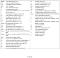
- the model computing unit 123 may output an electrode potential with inputs of a charge state of the battery 110 and a side reaction amount of the electrode through an OCV model obtained from [Equation 1] to [Equation 11] described below. Parameters shown in FIG. 5 may be referred to in relation to the following equations.
- the model computing unit 123 may obtain an electrode potential as described through [Equation 1] provided below.
- U p U p ⁇ p
- U n U n ⁇ n
- a positive electrode potential U P may be obtained based on a concentration X P of solid-phase lithium ions for the positive electrode
- a negative electrode potential U n may be obtained based on a concentration X n of solid-phase lithium ions for the negative electrode.
- the model computing unit 123 may obtain the concentration X P of solid-phase lithium ions for the positive electrode and the concentration X n of solid-phase lithium ions for the negative electrode, as described in [Equation 2] to [Equation 7] provided below.
- the model computing unit 123 may determine the positive electrode OCV change profile and the negative electrode OCV change profile through the OCV model described through [Equation 2] and [Equation 3].
- the positive electrode OCV change profile Qccb (X p , BOL ) may be determined based on a sum of a theoretical capacity of the positive electrode and an initial offset of the positive electrode in a fresh state where aging does not occur.
- the negative electrode OCV change profile Qccb (X n , BOL ) may be determined based on a sum of a theoretical capacity of the negative electrode and an initial offset of the negative electrode in a fresh state where aging does not occur.
- the model computing unit 123 may compute the initial offset of the negative electrode through the OCV model described based on [Equation 4] and [Equation 5].
- the model computing unit 123 may obtain the concentration of the solid-phase lithium ions for the electrode through the OCV model described based on [Equation 6] and [Equation 7].
- Q CCB ⁇ p c s , max , p L p A c ⁇ s , p F 3600 ⁇ p + Q side , p t
- Q CCB ⁇ n c s , max , n L n A c ⁇ s , n F 3600 ⁇ n + Q offset , n 0 + Q side , n t
- the concentration X P of solid-phase lithium ions for the positive electrode may be computed using [Equation 6]
- concentration X n of solid-phase lithium ions for the negative electrode may be computed using [Equation 7].
- the model computing unit 123 may compute the electrode potential through the OCV model described based on [Equation 8] to [Equation 11].
- U FC Q CCB U p 3600 F 1 c s , max , p L p A c ⁇ s , p Q CCB ⁇ Q side , p t ⁇ U n 3600 F 1 c s , max , n L n A c ⁇ s , n Q CCB ⁇ Q offset , n 0 ⁇ Q side , n t
- the model computing unit 123 may put the concentration of solid-phase lithium ions for the electrode, computed using [Equation 6] and [Equation 7], into [Equation 1], as can be seen from [Equation 8].
- the model computing unit 123 may compute a full-cell potential U FC, SOC0 at an SOC of 0 % and a full-cell potential U FC, SOC100 at an SOC of 100 %, as in [Equation 9] provided below.
- the model computing unit 123 may compute an electrode potential for a point on a charge balance axis where the full-cell potential U FC, SOC0 at an SOC of 0 % and the full-cell potential U FC, SOC100 at an SOC of 100 % correspond to preset values, as in [Equation 10] and [Equation 11] provided below.
- the model computing unit 123 may obtain a side reaction state based on a potential of an electrode.
- the model computing unit 123 may obtain the side reaction state by using the potential of the electrode (e.g., the equilibrium potential of the negative electrode and the positive electrode and the capacity differential value of the equilibrium potential) and the side reaction amount of the electrode.
- the potential of the electrode e.g., the equilibrium potential of the negative electrode and the positive electrode and the capacity differential value of the equilibrium potential
- the model computing unit 123 may obtain the side reaction state of the electrode by using the OCV model described based on [Equation 11] provided below.
- the model computing unit 123 may use ordinary differential equations that integrate the side reaction amount of the electrode by using the potential of the electrode to obtain the side reaction state of the electrode.
- the model computing unit 123 may obtain the side reaction state of the electrode by using the OCV model described based on [Equation 12] provided below.
- the model computing unit 123 may approximate the side reaction amount based on an assumption that the equilibrium potential of the electrode does not change greatly with aging of the battery 110, and obtain the side reaction state of the electrode by using the side reaction amount.
- the deterioration estimating unit 125 may estimate deterioration of the battery 110 based on the side reaction state of the electrode, obtained by the model computing unit 123.
- the deterioration estimating unit 125 may obtain a state of health (SOH) and/or a self-discharge voltage of the battery 110.
- SOH state of health
- the deterioration estimating unit 125 may estimate deterioration of the battery 110 by using the OCV model described based on [Equation 13] to [Equation 15].
- the state of health of the battery 110 may be obtained and a self-discharge voltage may be obtained based on [Equation 15].
- the state identifying unit 127 may determine the state of the battery 110 based on an estimation result of the deterioration estimating unit 125.
- the state identifying unit 127 may determine the degradation state of the battery 110 based on the state of health and/or the self-discharge voltage of the battery 110. A determination result of the state identifying unit 127 may be output through the output device 130.
- the diagnosis system 100 may include the battery 110, the diagnosis apparatus 120, and the output device 130.
- the diagnosis system 100 may include the battery 110, the diagnosis apparatus 120, and the output device 130.
- this is merely an example, and various embodiments are not limited thereto.
- at least one of the components described with reference to FIG. 1A may be omitted from components of the diagnosis system 100 or other components than the above-described components may be added as components of the diagnosis system.
- various types of loads configured to operate as power supplied from the battery 110 may be added as components of the diagnosis system 110.
- the components of the diagnosis apparatus 120 may not be limited to the components shown in FIG. 1B .
- at least one of the components shown in FIG. 1B may be omitted from the components of the diagnosis system 120 or one or more other components may be added as components of the diagnosis apparatus 120.
- At least one of the above-described components may be integrated with other components.
- Such a diagnosis apparatus 120 may be provided as a component of a battery management system or as a separate component distinguished from the battery management system.
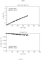
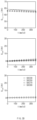
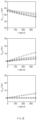
- FIGS. 3A to 3G show a result of performance comparison between a diagnosis apparatus according to various embodiments and a diagnosis apparatus according to a comparative embodiment.
- a diagnosis result of a diagnosis apparatus using a physics-based model e.g., an SPM model
- a diagnosis result of a diagnosis apparatus using a model e.g., a lumped OCV model
- a model e.g., a lumped OCV model
- a side reaction state and a discharge voltage measured in the diagnosis apparatus according to various embodiments are similar to a result measured in the diagnosis apparatus according to a comparative embodiment.
- measurement periods of the side reaction state and the discharge voltage are shorter in the diagnosis apparatus according to various embodiments than in the diagnosis apparatus according to the comparative embodiment.
- Such a measurement result may be equally identified in a second charge state (e.g., SOC 70) and a third charge state (e.g., SOC 90) of the battery 100. It may be seen from this point that the diagnosis apparatus according to various embodiments may derive a measurement result similar to the diagnosis apparatus according to the comparative embodiment, but more quickly derive a measurement result than the diagnosis apparatus according to the comparative embodiment.
- SOC 70 second charge state
- SOC 90 third charge state
- a measurement result of the diagnosis apparatus according to various embodiments and a measurement result of the diagnosis apparatus according to the comparative embodiment are similar to each other even in an aging process performed after manufacturing of the battery 100.
- FIG. 3D shows a side reaction state (e.g., a side reaction state QFULLCELL, a negative electrode side reaction state QASR, and a positive electrode side reaction state QCSR of a full-cell electrode) of an electrode, measured in a state of aging batteries of various SOC levels (e.g., SOCs of 30, 50, 70, and 90) under a first temperature condition (e.g., a temperature of 25 'C) for one year (calendar aging).
- FIG. 3E shows a side reaction state of an electrode, measured in an aging state under a second temperature condition (e.g., a temperature of 45 'C), and FIG.
- FIGS. 3D to 3F shows a side reaction state of an electrode, measured in an aging state under a third temperature condition (e.g., a temperature of 60 'C).
- a circle indicates a measurement result of the diagnosis apparatus according to the comparative embodiment
- a solid line indicates a measurement result of the diagnosis apparatus according to various embodiments
- a dashed line indicates an analytical solution of the diagnosis apparatus according to various embodiments.
- the diagnosis apparatus may derive a superior measurement result.
- FIG. 4 is a flowchart showing a battery diagnosis operation of a diagnosis system according to various embodiments. Operations in the following embodiment may be sequentially performed, but may not be necessarily sequentially performed. For example, the order of operations may be changed and at least two operations may be performed in parallel.
- the diagnosis system 100 may obtain battery information related to the battery 110, in operation 410.
- the diagnosis system 100 may obtain a voltage, a current, a temperature, and an SOC of the battery 110 as battery information.
- the diagnosis system 100 may obtain a side reaction amount accumulated in the electrode as the battery information.
- the diagnosis system 100 may compute an equilibrium potential for the electrode based on the obtained battery information, in operation 420.
- the diagnosis system 100 may obtain the equilibrium potential based on a concentration of solid-phase lithium ions for the electrode.
- the diagnosis system 100 may obtain the concentration of solid-phase lithium ions for the electrode based on an OCV model (e.g., a lumped OCV model) described in [Equation 2] to [Equation 10].
- the diagnosis system 100 may estimate deterioration of the battery 100 based on the side reaction state of the electrode, in operation 440.
- the diagnosis system 100 may obtain an SOH and/or a self-discharge voltage of the battery 110.
- the diagnosis system 100 may estimate the state of health and/or the self-discharge voltage of the battery 110 by using the OCV model described in [Equation 13] to [Equation 15].
- the diagnosis system 100 may determine the state of the battery 110 based on the state of health and/or the self-discharge voltage of the battery 110. According to an embodiment, the diagnosis system 100 may determine the degradation state of the battery 110 and output a determination result through the output device 130.
Landscapes
- Physics & Mathematics (AREA)
- General Physics & Mathematics (AREA)
- Engineering & Computer Science (AREA)
- Chemical & Material Sciences (AREA)
- Manufacturing & Machinery (AREA)
- Chemical Kinetics & Catalysis (AREA)
- Electrochemistry (AREA)
- General Chemical & Material Sciences (AREA)
- Microelectronics & Electronic Packaging (AREA)
- Materials Engineering (AREA)
- Secondary Cells (AREA)
- Tests Of Electric Status Of Batteries (AREA)
Applications Claiming Priority (2)
| Application Number | Priority Date | Filing Date | Title |
|---|---|---|---|
| KR1020220122902A KR102670278B1 (ko) | 2022-09-27 | 2022-09-27 | 배터리의 퇴화 상태를 진단하기 위한 시스템 및 방법 |
| PCT/KR2023/015014 WO2024072092A1 (ko) | 2022-09-27 | 2023-09-27 | 배터리의 퇴화 상태를 진단하기 위한 시스템 및 방법 |
Publications (2)
| Publication Number | Publication Date |
|---|---|
| EP4575538A1 true EP4575538A1 (de) | 2025-06-25 |
| EP4575538A4 EP4575538A4 (de) | 2025-10-01 |
Family
ID=90478699
Family Applications (1)
| Application Number | Title | Priority Date | Filing Date |
|---|---|---|---|
| EP23873201.0A Pending EP4575538A4 (de) | 2022-09-27 | 2023-09-27 | System und verfahren zur diagnose des verschlechterungszustands einer batterie |
Country Status (6)
| Country | Link |
|---|---|
| US (1) | US20260092981A1 (de) |
| EP (1) | EP4575538A4 (de) |
| JP (1) | JP2025531254A (de) |
| KR (1) | KR102670278B1 (de) |
| CN (1) | CN119866450A (de) |
| WO (1) | WO2024072092A1 (de) |
Families Citing this family (1)
| Publication number | Priority date | Publication date | Assignee | Title |
|---|---|---|---|---|
| KR20250162217A (ko) * | 2024-05-10 | 2025-11-18 | 주식회사 엘지에너지솔루션 | 배터리 진단 방법 및 장치 |
Family Cites Families (8)
| Publication number | Priority date | Publication date | Assignee | Title |
|---|---|---|---|---|
| KR101696313B1 (ko) * | 2014-10-24 | 2017-01-13 | 주식회사 엘지화학 | 이차전지의 퇴화에 따른 soc-ocv 프로파일 추정 방법 |
| KR102527326B1 (ko) * | 2015-08-20 | 2023-04-27 | 삼성전자주식회사 | 배터리 충전 상태(SoC)를 예측하는 배터리 시스템 및 방법 |
| KR102258833B1 (ko) * | 2017-09-28 | 2021-05-31 | 주식회사 엘지에너지솔루션 | 리튬 이온 배터리 셀의 퇴화 정보를 획득하는 장치 |
| KR102156404B1 (ko) * | 2018-01-09 | 2020-09-15 | 주식회사 엘지화학 | 배터리 셀 성능 테스트 장치 및 방법 |
| KR102452626B1 (ko) * | 2018-03-07 | 2022-10-06 | 주식회사 엘지에너지솔루션 | Soc-ocv 프로파일 추정 방법 및 장치 |
| US11283103B2 (en) * | 2018-10-26 | 2022-03-22 | Hyundai Motor Company | System and method for rapid charging lithium ion battery |
| KR102405514B1 (ko) * | 2018-12-06 | 2022-06-03 | 주식회사 엘지에너지솔루션 | 이차 전지의 충전 장치 및 방법 |
| JP2022026770A (ja) * | 2020-07-31 | 2022-02-10 | プライムアースEvエナジー株式会社 | リチウムイオン二次電池のLi析出抑制制御方法、リチウムイオン二次電池の制御装置 |
-
2022
- 2022-09-27 KR KR1020220122902A patent/KR102670278B1/ko active Active
-
2023
- 2023-09-27 US US19/113,773 patent/US20260092981A1/en active Pending
- 2023-09-27 EP EP23873201.0A patent/EP4575538A4/de active Pending
- 2023-09-27 CN CN202380065826.3A patent/CN119866450A/zh active Pending
- 2023-09-27 WO PCT/KR2023/015014 patent/WO2024072092A1/ko not_active Ceased
- 2023-09-27 JP JP2025516000A patent/JP2025531254A/ja active Pending
Also Published As
| Publication number | Publication date |
|---|---|
| KR102670278B1 (ko) | 2024-05-30 |
| WO2024072092A1 (ko) | 2024-04-04 |
| CN119866450A (zh) | 2025-04-22 |
| KR20240043608A (ko) | 2024-04-03 |
| US20260092981A1 (en) | 2026-04-02 |
| JP2025531254A (ja) | 2025-09-19 |
| EP4575538A4 (de) | 2025-10-01 |
Similar Documents
| Publication | Publication Date | Title |
|---|---|---|
| KR102633335B1 (ko) | 리튬이온 배터리팩의 비정상 셀 검출 및 soh 예측 방법 | |
| EP4131571B1 (de) | Batterieverwaltungsvorrichtung und -verfahren | |
| EP3644079B1 (de) | Vorrichtung und verfahren zum testen der leistung einer batteriezelle | |
| Dalal et al. | Lithium-ion battery life prognostic health management system using particle filtering framework | |
| US11372050B2 (en) | Apparatus and method for estimating state of charge of secondary battery | |
| US8548762B2 (en) | Method of estimating the non-measurable characteristics of an electrochemical system | |
| Pop et al. | State-of-the-art of battery state-of-charge determination | |
| EP3674730B1 (de) | Vorrichtung und verfahren zur batteriediagnose | |
| EP3056918B1 (de) | Vorrichtung zur schätzung des zustandes einer hybridsekundärbatterie und verfahren dafür | |
| KR102572652B1 (ko) | 배터리의 충전상태를 추정하는 방법 | |
| KR101227417B1 (ko) | 리튬이온전지의 충전상태 추정방법 및 이 방법을 구현하기 위한 시스템 | |
| Farag | Lithium-ion batteries: Modelling and state of charge estimation | |
| JP2023523370A (ja) | リチウムメッキを検出するための方法及び装置、並びに分極比率を取得するための方法及び装置 | |
| US20130311116A1 (en) | Battery System and Method with SOC/SOH Observer | |
| US20220196754A1 (en) | Method for detecting abnormal battery cell | |
| US20220268856A1 (en) | Method for detecting internal short-circuited cell | |
| EP4109118B1 (de) | Batterievorrichtung und verfahren zur vorhersage der batterieleistung | |
| EP4418404A1 (de) | Druck- oder spannungsschätzung für wiederaufladbare batterien | |
| EP4119961B1 (de) | Batterievorrichtung und verfahren zur schätzung des batteriezustands | |
| KR20200031532A (ko) | 2 차 전지 시스템 및 2 차 전지의 내부 상태 추정 방법 | |
| US20230324463A1 (en) | Method and Apparatus for Operating a System for Detecting an Anomaly of an Electrical Energy Store for a Device by Means of Machine Learning Methods | |
| EP4498103A1 (de) | Batterieverwaltungsvorrichtung und -verfahren | |
| EP4632400A1 (de) | Vorrichtung zur vorhersage der in einer batterie erzeugten gasmenge und betriebsverfahren dafür | |
| EP4575538A1 (de) | System und verfahren zur diagnose des verschlechterungszustands einer batterie | |
| Juang | Online battery monitoring for state-of-charge and power capability prediction |
Legal Events
| Date | Code | Title | Description |
|---|---|---|---|
| STAA | Information on the status of an ep patent application or granted ep patent |
Free format text: STATUS: THE INTERNATIONAL PUBLICATION HAS BEEN MADE |
|
| PUAI | Public reference made under article 153(3) epc to a published international application that has entered the european phase |
Free format text: ORIGINAL CODE: 0009012 |
|
| STAA | Information on the status of an ep patent application or granted ep patent |
Free format text: STATUS: REQUEST FOR EXAMINATION WAS MADE |
|
| 17P | Request for examination filed |
Effective date: 20250318 |
|
| AK | Designated contracting states |
Kind code of ref document: A1 Designated state(s): AL AT BE BG CH CY CZ DE DK EE ES FI FR GB GR HR HU IE IS IT LI LT LU LV MC ME MK MT NL NO PL PT RO RS SE SI SK SM TR |
|
| A4 | Supplementary search report drawn up and despatched |
Effective date: 20250902 |
|
| RIC1 | Information provided on ipc code assigned before grant |
Ipc: G01R 31/367 20190101AFI20250827BHEP Ipc: G01R 31/392 20190101ALI20250827BHEP Ipc: G01R 31/3835 20190101ALI20250827BHEP Ipc: G01R 31/36 20200101ALI20250827BHEP Ipc: G01R 31/378 20190101ALI20250827BHEP Ipc: H01M 10/052 20100101ALI20250827BHEP |
|
| DAV | Request for validation of the european patent (deleted) | ||
| DAX | Request for extension of the european patent (deleted) | ||
| REG | Reference to a national code |
Ref country code: DE Ref legal event code: R079 Free format text: PREVIOUS MAIN CLASS: G01R0031367000 Ipc: G01R0031384200 |
|
| GRAP | Despatch of communication of intention to grant a patent |
Free format text: ORIGINAL CODE: EPIDOSNIGR1 |
|
| STAA | Information on the status of an ep patent application or granted ep patent |
Free format text: STATUS: GRANT OF PATENT IS INTENDED |
|
| GRAJ | Information related to disapproval of communication of intention to grant by the applicant or resumption of examination proceedings by the epo deleted |
Free format text: ORIGINAL CODE: EPIDOSDIGR1 |
|
| STAA | Information on the status of an ep patent application or granted ep patent |
Free format text: STATUS: REQUEST FOR EXAMINATION WAS MADE |
|
| GRAP | Despatch of communication of intention to grant a patent |
Free format text: ORIGINAL CODE: EPIDOSNIGR1 |
|
| STAA | Information on the status of an ep patent application or granted ep patent |
Free format text: STATUS: GRANT OF PATENT IS INTENDED |
|
| RIC1 | Information provided on ipc code assigned before grant |
Ipc: G01R 31/3842 20190101AFI20260307BHEP Ipc: G01R 31/3832 20190101ALI20260307BHEP Ipc: G01R 31/367 20190101ALI20260307BHEP Ipc: G01R 31/392 20190101ALI20260307BHEP Ipc: G01R 31/3835 20190101ALI20260307BHEP Ipc: H01M 10/42 20060101ALI20260307BHEP Ipc: H01M 10/48 20060101ALI20260307BHEP Ipc: H01M 10/0525 20100101ALI20260307BHEP |