EP4575588A1 - Suivi magnétique à grande échelle - Google Patents
Suivi magnétique à grande échelle Download PDFInfo
- Publication number
- EP4575588A1 EP4575588A1 EP23219848.1A EP23219848A EP4575588A1 EP 4575588 A1 EP4575588 A1 EP 4575588A1 EP 23219848 A EP23219848 A EP 23219848A EP 4575588 A1 EP4575588 A1 EP 4575588A1
- Authority
- EP
- European Patent Office
- Prior art keywords
- circuit board
- assembly
- location
- magnetic object
- processing circuit
- Prior art date
- Legal status (The legal status is an assumption and is not a legal conclusion. Google has not performed a legal analysis and makes no representation as to the accuracy of the status listed.)
- Pending
Links
Images



Classifications
-
- G—PHYSICS
- G01—MEASURING; TESTING
- G01V—GEOPHYSICS; GRAVITATIONAL MEASUREMENTS; DETECTING MASSES OR OBJECTS; TAGS
- G01V3/00—Electric or magnetic prospecting or detecting; Measuring magnetic field characteristics of the earth, e.g. declination, deviation
- G01V3/08—Electric or magnetic prospecting or detecting; Measuring magnetic field characteristics of the earth, e.g. declination, deviation operating with magnetic or electric fields produced or modified by objects or geological structures or by detecting devices
- G01V3/081—Electric or magnetic prospecting or detecting; Measuring magnetic field characteristics of the earth, e.g. declination, deviation operating with magnetic or electric fields produced or modified by objects or geological structures or by detecting devices the magnetic field is produced by the objects or geological structures
-
- G—PHYSICS
- G01—MEASURING; TESTING
- G01V—GEOPHYSICS; GRAVITATIONAL MEASUREMENTS; DETECTING MASSES OR OBJECTS; TAGS
- G01V3/00—Electric or magnetic prospecting or detecting; Measuring magnetic field characteristics of the earth, e.g. declination, deviation
- G01V3/08—Electric or magnetic prospecting or detecting; Measuring magnetic field characteristics of the earth, e.g. declination, deviation operating with magnetic or electric fields produced or modified by objects or geological structures or by detecting devices
-
- G—PHYSICS
- G01—MEASURING; TESTING
- G01V—GEOPHYSICS; GRAVITATIONAL MEASUREMENTS; DETECTING MASSES OR OBJECTS; TAGS
- G01V3/00—Electric or magnetic prospecting or detecting; Measuring magnetic field characteristics of the earth, e.g. declination, deviation
- G01V3/08—Electric or magnetic prospecting or detecting; Measuring magnetic field characteristics of the earth, e.g. declination, deviation operating with magnetic or electric fields produced or modified by objects or geological structures or by detecting devices
- G01V3/087—Electric or magnetic prospecting or detecting; Measuring magnetic field characteristics of the earth, e.g. declination, deviation operating with magnetic or electric fields produced or modified by objects or geological structures or by detecting devices the earth magnetic field being modified by the objects or geological structures
Definitions
- the present disclosure relates to the technical field of determining and/or tracking a location of passive accessories, more specifically to an assembly and a system for tracking and/or determining a location of at least one magnetic object, to a method of assembling the assembly and the system, and to a method for tracking and/or determining a location of at least one magnetic object.
- the provision of a plurality of magnetometers allows to measure a magnetic field associated with a magnetic object which may be arranged in or coupled to the user-borne device.
- the user-borne devices using this technology may be electronically and/or electrically passive. More specifically, electrically passive means that the user-borne device may not comprise a power source (e.g., batteries) and/or means to receive power (e.g., wireless power transmission via an inductive coil) for powering an electronic feature of the user-borne device. Electronically passive means that no computation or processing occurs (or happens) on the user-borne device.
- the magnetometer measurements enable determining and/or tracking of the location of the magnetic object within a sensing volume (and/or area) created by the plurality of magnetometers.
- the magnetic object may be arranged within a writing device (e.g., a stylus) which may be operated by a user on a writing support during a user operation. Based on the magnetic field measurements associated with the magnetic object, a location of the writing device on the writing support may be determined.
- a writing device e.g., a stylus
- the determination and/or tracking of a location of at least one magnetic object with a plurality of magnetometers may be provided in at least five degrees of freedom. Some applications, like the writing device embodiment as described above, may require a sensing area in the size of a sheet of paper and a corresponding sensing volume (e.g., an elliptical volume in which a sheet of paper fits).
- assemblies and systems for determination and/or tracking of a location of at least one magnetic object usually comprise a single printed circuit board assembly (PCBA) wherein all components required for tracking and/or determining the location of the at least one magnetic object are mounted on the single printed circuit board (PCB).
- PCBA printed circuit board assembly
- some applications may require a larger sensing volume (or area), e.g., larger than the size of the sheet of paper and the associated volume, or a sensing volume that should be adapted to certain applications and arrangements.
- a larger sensing volume (and/or area) is required, the assemblies and systems with a single PCBA have to be provided in a larger format.
- extending the size of a single PCBA may lead to increased costs, higher complexity in manufacture and poor applicability.
- the object of the present disclosure is to provide an improved assembly, system and/or method for tracking and/or determining a location of at least one magnetic object, and more specifically which can provide an enlarged and/or application-oriented sensing volume (and/or area) in a simplified manner.
- the present disclosure relates to an assembly for tracking and/or determining a location of at least one magnetic object as defined in claim 1 and a system for tracking and/or determining a location of at least one magnetic object as defined in claim 8. Furthermore, the present disclosure relates to a method of assembling an assembly for tracking and/or determining a location of at least one magnetic object as defined in claim 12. In addition, the present disclosure relates to a method, more specifically a computer-implemented method, for tracking and/or determining a location of at least one magnetic object as defined in claim 13.
- the dependent claims depict advantageous embodiments of the present disclosure.
- an assembly for tracking and/or determining a location of at least one magnetic object comprises a processing circuit board, at least one connecting circuit board, and at least one sensing circuit board comprising at least one magnetometer.
- the at least one connecting circuit board is mechanically and communicatively coupled with the processing circuit board.
- the at least one sensing circuit board is mechanically and communicatively coupled with the at least one connecting circuit board.
- the assembly according to the first aspect of the present disclosure provides a modular structure with individual circuit boards forming individual modules that can be coupled with each other.
- required components may be provided on the individual circuit boards.
- additional modules e.g., sensing circuit boards and/or connecting circuit boards
- the modular structure of the assembly may be simply adapted and extended. Thereby, a flexible and customizable architecture of the assembly can be provided, manufacturing costs can be reduced, an applicability can be improved, and the assembly can be simplified.
- sensing circuit boards and/or connecting circuit boards can be added to or removed from the assembly and/or system without changing the entire architecture.
- the at least one magnetometer may be configured to create a sensing volume.
- the processing circuit board may be configured to receive the magnetic field measurements measured with the at least one magnetometer via the at least one connecting circuit board.
- the processing circuit board, the connecting circuit board and/or the sensing circuit board may comprise a rectangular, flat shape.
- a system for tracking and/or determining a location of at least one magnetic object may comprise a first assembly for tracking and/or determining a location of at least one magnetic object and at least one second assembly for tracking and/or determining a location of at least one magnetic object.
- At least one of the first assembly and the at least one second assembly may be an assembly according to the first aspect of the present disclosure.
- each of the first assembly and the at least one second assembly may be an assembly according to the first aspect of the present disclosure.
- the first assembly and the at least one second assembly may be (at least) communicatively coupled with each other.
- additional modules e.g., sensing circuit boards and/or connecting circuit boards
- assemblies can be easily coupled with the already existing modules (i.e., the circuit boards) and/or assemblies.
- a flexible and customizable architecture of the system can be provided, manufacturing costs can be reduced, an applicability can be improved, and the system can be simplified.
- assemblies according to the first aspect of the present disclosure can be added to or removed from the system without changing the entire architecture.
- a scalable system can be provided and a faster adaption and/or initialization of separate sensing areas can be achieved.
- a method of assembling an assembly for tracking and/or determining a location of at least one magnetic object comprises:
- Steps b) and c) can also be carried out the other way round.
- the above-described effects and advantages for the assembly may apply analogously to the method.
- the method may allow for flexible and customizable assembling of the assembly. Furthermore, manufacturing costs can be reduced, an applicability can be improved, and the assembly can be simplified.
- a method of assembling a system for tracking and/or determining a location of at least one magnetic object comprises:
- At least one of the first assembly and the at least one second assembly may be assembled by a method according to the third aspect of the present disclosure. At least one of the first assembly and the at least one second assembly may be an assembly according to the first aspect of the present disclosure. Steps b) and c) can also be carried out the other way round.
- the above-described effects and advantages for the system and assembly may apply analogously to the method.
- the method may allow for flexible and customizable assembling of the system.
- a method for tracking and/or determining a location of at least one magnetic object comprises:
- each of the first assembly and the at least one second assembly may be an assembly according to the first aspect of the present disclosure.
- the first assembly and the at least one second assembly may be of (or comprised with) a system for tracking and/or determining a location of at least one magnetic object, more specifically of (or comprised with) a system according to the second aspect of the present disclosure.
- Each of the assemblies may comprise at least one processing unit. At least one processing unit may be configured to execute the method (or steps of the method).
- the first magnetic field measurements may be generated with at least one first sensing circuit board comprising at least one first magnetometer of the first assembly.
- the first magnetic field measurements may be collected with a first processing circuit board comprising at least one first processing unit of the first assembly.
- the second magnetic field measurements may be generated with at least one second sensing circuit board comprising at least one second magnetometer of the at least one second assembly.
- the second magnetic field measurements may be collected with a second processing circuit board comprising at least one second processing unit of the at least one second assembly.
- the method may provide an improved tracking and/or determination of a location of at least one magnetic object of a system according to the second aspect of the present disclosure. Based on the method as defined above, an error in magnetic object location determination, in particular when the at least one magnetic object moves from the first assembly to the at least one second assembly, can be reduced.
- an improved method for a system comprising a modular structure as defined for the second aspect of the present disclosure may be provided.
- the respective assemblies can share magnetic field measurements (and associated data) and/or determined magnetic object location data (which may be determined based on the magnetic field measurements) to determine a location of the magnetic object with increased accuracy, even during transition from the first assembly to the second assembly (especially in an edge area of the respective assemblies).
- a signal to noise ratio during measuring with the magnetometers which can occur when the at least one magnetic object is operated in the edge area of the respective assembly, can be increased thus leading to increased accuracy. Furthermore, since the respective assemblies already receive the magnetic object location data from the respective other assembly, a time required for tracking the at least one magnetic object may be reduced. By exchanging the magnetic field measurements and/or magnetic object location data between the assemblies, a sensing volume (and/or area) may be easily extended.
- Fig. 1 is a schematic view of a system 1 and an assembly 10 for tracking and/or determining a location of at least one magnetic object 20 according to aspects of the present disclosure. At least one magnetic object 20 is operated within a sensing volume M and/or area.
- the assembly 10 for tracking and/or determining a location of at least one magnetic object 20 comprises a processing circuit board 110, at least one connecting circuit board 120, and at least one sensing circuit board 130 comprising at least one magnetometer 140.
- the at least one connecting circuit board 120 is mechanically and communicatively coupled with the processing circuit board 110.
- the at least one sensing circuit board 130 is mechanically and communicatively coupled with the at least one connecting circuit board 120.
- Each magnetometer 140, 150 may be configured to measure the magnetic field created by the at least one magnetic object 20 in the direction of the first reference axis X, the second reference axis Y, and/or the vertical reference axis Z. In other words, each magnetometer 140, 150 may be configured to perform magnetic field measurements in the direction of one axis (i.e., one dimension), two axes (i.e., two dimensions), or three axes (i.e., three dimensions). The number of magnetometers provided may depend on the desired size of the sensing volume M and/or area within which at least one magnetic object 20 is operated.
- the at least one magnetometer 140, 150 may be configured to collect magnetic field measurements associated with the magnetic object 20 within the sensing volume M up to a maximum measurement distance, wherein the maximum measurement distance may be a distance within which the magnetic field measurements can be provided with acceptable reliability and/or accuracy. In embodiments, the maximum measurement distance may be 18cm, more specifically 15cm.
- the at least one magnetic object 20 may be operated within the maximum measurement distance.
- the minimum magnetic field generated by at least one magnetic object 20 that may be tracked with the assembly 10 and/or system 1 may comprise at least 1 micro tesla, e.g., which may be provided within the distance as mentioned above.
- the user-borne device 2 may be a computer mouse, a keyboard, a toy, a stylus, a writing and/or drawing device (e.g., a pen), a marker or a dial.
- the user-borne device 2 may be operable on an interaction surface (not shown in Fig. 1 ).
- the assembly 10 and/or system 1 may be configured to track a movement of the user-borne device 2 based on determining a location of the at least one magnetic object 20 (and an associated user-borne device location).
- the user-borne device 100 may comprise a device coordinate system.
- the device coordinate system may comprise the first device axis x d , the second device axis y d orthogonal to the first device axis x d , and a vertical device axis z d .
- the vertical device axis z d may be orthogonal to a device contact surface or point and/or orthogonal to a plane defined by the first device axis x d and the second device axis y d .
- the device contact surface or point may be the part of the user-borne device 2 which, during a user operation, may be in contact with an interaction surface (i.e., the surface on which the user-borne device may be operated in some embodiments).
- the user-borne device may be a computer mouse.
- the user-borne device 2 may comprise a contact point (e.g., a stylus or other writing device comprising a writing tip with a nib which contacts an interaction surface during a writing operation).
- the user-borne device 2 may be an erasing device or a writing device having an erasing feature.
- the user-borne device 2 may comprise contact surface (e.g., the erasing feature) and/or contact point (e.g., the nib).
- the user-borne device may be operated within a sensing volume M but not on the interaction surface (i.e., in the air).
- the user-borne device 100 may be used, e.g., as a pointer.
- the device coordinate system may be defined within a geometric center of the user-borne device 2.
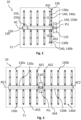
- Figs. 2 to 5 are schematic top views of embodiments of the assembly 10 according to aspects of the present disclosure. The features and aspects of respective embodiments described below may be combined with each other.
- the assembly 10 may comprise a housing 11 that is accommodating the processing circuit board 110, the at least one connecting circuit board 120 and the at least one sensing circuit board 130.
- the housing 11 may be or may comprise a furniture (e.g., a table), an electronics device (e.g., a notebook, a laptop, or a tablet), a screen, a wall, a presentation board, a whiteboard, a paper board, a trackpad, or a touchpad.
- the housing 11 may comprise a flexible or a rigid material.
- the housing 11 may comprise coupling means (e.g., non-positive or friction fit coupling means, and/or positive coupling means) configured to couple the housing 11 to another device.
- the at least one sensing circuit board 130 may be mechanically and communicatively coupled with the processing circuit board 110 via the at least one connecting circuit board 120.
- Each of the processing circuit board 110, the at least one connecting circuit board 120 and the at least one sensing circuit board 130 may be provided as a separate circuit board, more specifically mechanically and communicatively coupled with each other.
- Each of the processing circuit board 110, the at least one connecting circuit board 120 and the at least one sensing circuit board 130 may comprise a printed circuit board (PCB).
- PCB printed circuit board
- each of the processing circuit board 110, the at least one connecting circuit board 120 and the at least one sensing circuit board 130 may be provided as a separate PCB relative to the other ones of the respective circuit boards.
- the processing circuit board 110, the at least one connecting circuit board 120 and the at least one sensing circuit board 130 may comprise a rigid PCB, a flexible PCB or a rigid-flex PCB.
- Rigid-flex PCBs are PCBs which are flexible (flex) and rigid at the same time.
- the assembly 10 as a whole can form a rigid-flex PCB.
- the processing circuit board 110 may comprise a rigid PCB
- the at least one connecting circuit board 120 may comprise a flexible PCB
- the at least one sensing circuit board 130 may comprise a rigid PCB.
- Only the at least one connecting circuit board 120 may be or comprise a flexible PCB and may directly couple the processing circuit board 110 and the at least one sensing circuit board 130.
- the at least one connecting circuit board 120 and/or the at least one sensing circuit board 130 may comprise a frangible material through which the boards 120, 130 may be broken at a desired location and assembled in a desired manner to provide a specific format.
- the processing circuit board 110 may comprise at least one processing unit PU.
- the processing circuit board 110 may comprise a PCB and the processing unit PU may be mounted on the PCB.
- the at least one processing unit PU may comprise a microprocessor, a microcontroller or a field programmable gate array (FPGA).
- the processing circuit board 110 more specifically the at least one processing unit PU, may be configured to collect magnetic field measurements measured with the at least one magnetometer 140.
- the processing circuit board 110, more specifically the at least one processing unit PU may be configured to process the collected magnetic field measurements to track and/or determine a location of the at least one magnetic object 20 within a sensing volume M (and/or area).
- the assembly 10, more specifically the at least one sensing circuit board 130 may comprise one or more first sensing circuit boards 130a and one or more second sensing circuit boards 130b, each comprising at least one magnetometer 140.
- the processing circuit board 110 and/or the at least one connecting circuit board 120 may comprise at least one additional magnetometer 150.
- the processing circuit board 110 and/or the at least one connecting circuit board 120 may comprise a plurality of additional magnetometers 150.
- the respective magnetometers 140, 150 may be mounted on the respective circuit boards 110, 120, 130.
- the assembly 10 may comprise a plurality of magnetometers 140 and/or a plurality of additional magnetometers 150.
- the plurality of magnetometers 140 and/or the plurality of additional magnetometers 150 may be distributed substantially uniformly over the entire assembly 10. Thereby, a homogeneous arrangement of the magnetometers 140, 150 can be provided throughout the assembly 10 to measure the magnetic field created by at least one magnetic object 20.
- the arrangement of the magnetometers 140, 150, relative to the entire assembly 10 may be determined by a physical area of the entire assembly 10 in combination with a density metric that may be indicative of a required number of magnetometers 140, 150 per area to provide sufficient magnetic field measurements for a desired sensing volume (and/or area), as well as sufficient accuracy for tracking and/or location determination.
- the density metric may ensure that the number of magnetometers per square cm may be substantially constant throughout the assembly 10.
- the at least one sensing circuit board 130 may comprise a plurality of magnetometers 140. The at least one sensing circuit board 130 may be arranged with respect to the at least one connecting circuit board 120 and the processing circuit board 110 such that the plurality of magnetometers 140 is distributed substantially uniformly over the entire assembly 10.
- the plurality of magnetometers 140 may be arranged on the at least one sensing circuit board 130 such that the uniform distribution may be achieved.
- the at least one sensing circuit board 130 may comprise a plurality of magnetometers 140 and the processing circuit board 110 and/or the at least one connecting circuit board 120 may comprise a plurality of additional magnetometers 150.
- the at least one sensing circuit board 130, the at least one connecting circuit board 120 and/or the processing circuit board 110 may be arranged with respect to each other such that the plurality of magnetometers 140 and the plurality of additional magnetometers 150 are distributed substantially uniformly over the entire assembly 10.
- At least one first sensing circuit board 130a may comprise a single magnetometer 140 and at least one second sensing circuit board 130b may comprise a plurality of magnetometers 140.
- the at least one first sensing circuit board 130a may comprise a first plurality of magnetometers 140a and the at least one second sensing circuit board 130b may comprise a second plurality of magnetometers 140b.
- the first plurality of magnetometers 140a may comprise a different number of magnetometers compared to the second plurality of magnetometers 140b.
- the respective magnetometers 140a, 140b may be separated from each other and distributed, more specifically uniformly distributed, over the respective sensing circuit board 130, 130a, 130b.
- the plurality of magnetometers 140 may be provided in a linear arrangement on the at least one sensing circuit board 130.
- the at least one first sensing circuit board 130a may comprise a first length 11 and may comprise a first plurality of magnetometers 140a distributed along the at least one first sensing circuit board 130a.
- the at least one second sensing circuit board 130b may comprise a second length l2 and may comprise a second plurality of magnetometers 140b distributed along the at least one second sensing circuit board 130b.
- the first length 11 may be larger than the second length l2 and the first plurality of magnetometers 140a may be larger than the second plurality of magnetometers 140b.
- each sensing circuit board 130 may comprise the same number of magnetometers.
- the respective sensing circuit boards may comprise a longitudinal shape, e.g., in the form of flat strips, on which the respective magnetometers are arranged.
- the processing circuit board 110, the at least one connecting circuit board 120 and the at least one sensor circuit board 130 are arranged in a common plane.
- the expression "common plane” may be defined as a plane which extends through each of the processing circuit board 110, the at least one connecting circuit board 120 and the at least one sensor circuit board 130.
- an assembly with reduced thickness may be provided, e.g., as shown in Figs. 2 to 4 .
- the at least one sensing circuit board 130 may be arranged above or below the at least one connecting circuit board 120.
- the expression "above or below” means that a plane extending through the at least one sensing circuit board 130 is parallel to or at an angle relative to a plane extending through the connecting circuit board 120.
- the processing circuit board 110 may also be arranged above or below the at least one connecting circuit board 120, or, have a common plane with the at least one connecting circuit board 130. In the embodiment shown in Fig. 5 , the processing circuit board 110, the at least one connecting circuit board 120 and the at least one sensor circuit board 130 may form a stack of circuit boards.
- the at least one sensing circuit board 130 may be coupled to a first side of the at least one connecting circuit board 120.
- the processing circuit board 110 may be coupled to a second side of the at least one connecting circuit board 120 different than the first side.
- the one or more first sensing circuit boards 130a may be coupled to a first side of the at least one connecting unit 120 and the one or more second sensing circuit boards 130b may be coupled to a second side of the at least one connecting unit 120.
- the second side may be opposite or adjacent (e.g., perpendicular) to the first side.
- the one or more first sensing circuit boards 130a and the one or more second sensing circuit boards 130b may be coupled to the at least one connecting circuit board 120 such that their respective longitudinal axes AS1, AS2 are substantially perpendicular to the longitudinal axis AC of the at least one connecting circuit board 120.
- the at least one connecting circuit board 120 may comprise a first connecting circuit board 120a and at least one second connecting circuit board 120b.
- the first connecting circuit board 120a may be coupled to a first side of the processing circuit board 110 and the at least one second connecting circuit board 120b may be coupled to a second side of the processing circuit board 110.
- the second side may be opposite or adjacent to the first side.
- the first connecting circuit board 120a and the at least one second connecting circuit board 120b may comprise a different size (e.g., length) which may be adapted to the number of sensing circuit boards that are coupled with the respective connecting circuit boards.
- the assembly 10, more specifically the at least one sensing circuit board 130 may comprise one or more third sensing circuit boards 130c and one or more fourth sensing circuit boards 130d, each comprising at least one magnetometer 140.
- the one or more third sensing circuit boards 130c and one or more fourth sensing circuit boards 130d may comprise a third and fourth longitudinal axis AS3, AS4.
- the one or more first sensing circuit boards 130a and the one or more third sensing circuit boards 130c may be coupled to opposite sides of the first connecting circuit board 120a, more specifically such that their respective longitudinal axes AS1, AS3 are substantially perpendicular to the longitudinal axis AC1 of the first connecting circuit board 120a.
- the at least one system housing may comprise coupling means (e.g., non-positive or friction fit coupling means, and/or positive coupling means) configured to couple the at least one system housing to another device or component.
- the at least one system housing may comprise a first housing 11a accommodating the first assembly 10a and at least one second housing 1 1b accommodating the at least one second assembly 10b.
- the first housing 11a and the at least one second housing 11b may be coupled with each other via respective coupling means as described above.
- the first processing circuit board 110a and the at least one second processing circuit board 1 10b, 110c, 110d may be communicatively coupled with each other. More specifically, the first processing circuit board 110a may comprise at least one first processing unit PU1 and the at least one second processing circuit board 110b, 110c, 110d may comprise at least one second processing unit PU2, PU3, PU4. The at least one first processing unit PU1 and the at least one second processing unit PU2, PU3, PU4 may be communicatively coupled with each other.
- the first processing circuit board 110a and/or the second processing circuit board 110b, 110c, 110d may be configured to collect magnetic field measurements measured with the at least one magnetometer 140 (or in case two assemblies according to the first aspect of the present disclosure are provided, at least two magnetometers 140). More specifically, the first assembly 10a may comprise at least one first magnetometer 140a, and the at least one second assembly 10b, 10c, 10d may comprise at least one second magnetometer 140b.
- the first processing circuit board 110a may be configured to collect first magnetic field measurements, more specifically measured with the at least one first magnetometer 140a.
- the at least one second processing circuit board 110b, 110c, 110d may be configured to collect second magnetic field measurements, more specifically measured with the at least one second magnetometer 140b.
- the first magnetic field measurements may be different from the second magnetic field measurements.
- the first processing circuit board 110a and/or the at least one second processing circuit board 1 10b, 1 10c, 110d may be configured to transmit and/or receive the respective magnetic field measurements to and/or from the respective other one of the first processing circuit board 110a and the second processing circuit board 110b, 110c, 110d.
- the at least one first processing unit PU1 and the at least one second processing unit PU2 may be configured to process the collected first and/or second magnetic field measurements.
- the first processing circuit board 110a and/or at least one second processing circuit board 110b, 110c, 110d (more specifically, the at least one first processing unit PU1 and/or the at least one second processing unit PU2) may be configured to track and/or determine a location of the at least one magnetic object 20 based on the processed first and/or second magnetic field measurements.
- the first processing circuit board 110a and/or the at least one second processing circuit board 110b, 110c, 110d may be configured to transmit and/or receive the respective magnetic object location to and/or from the respective other one of the first processing circuit board 110a and the second processing circuit board 110b, 110c, 110d.
- the first processing circuit board 110a, and the at least one second processing circuit 110b, 110c, 110d may each comprise a transmitting component and/or a receiving component, e.g., to establish a wireless connection.
- the first processing circuit board 110a and the at least one second processing circuit board 110b, 110c, 110d may be communicatively coupled with each other by a wired connection.
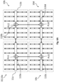
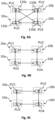
- FIG. 6A illustrates four assemblies 10a-d communicatively coupled with each other.
- more assemblies 10 or less (e.g., three) assemblies 10 may be provided and coupled with each other.
- Fig. 6A illustrates four assemblies 10a-d as shown in Fig. 3 coupled with each other (i.e., coupling four "fish-bone assemblies” with each other).
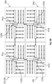
- Fig. 6B illustrates four assemblies as shown in Fig. 4 coupled with each other (i.e., coupling four "wheel assemblies” with each other) - however, without the embodiment of fifth one or more sensing circuit boards 130e.
- the "fish-bone assembly” may also be combined with the "wheel assembly”.
- the system 1 may further comprise a third assembly 10c and at least one fourth assembly 10d, each for tracking and/or determining a location of at least one magnetic object 20.
- Each of the third assembly 10c and the at least one fourth assembly 10d may be an assembly 10 according to the first aspect of the present disclosure.
- the third assembly 10c may comprise a third processing circuit board 110c and the at least one fourth assembly 10d may comprise a fourth processing circuit board 110d.
- the first assembly 10a, the second assembly 10b, the third assembly 10c and the fourth assembly 10d may be communicatively coupled with each other.
- the respective assemblies 10a-d may be communicatively coupled with each other by a wireless connection. In other embodiments, the respective assemblies 10a-d may be communicatively coupled with each other by a wired connection. In embodiments, the first assembly 10a, the second assembly 10b, the third assembly 10c and the at least one fourth assembly 10d may be mechanically coupled with each other. In embodiments, the respective assemblies 10a-d may also communicate with each other via the mechanical couplings. In such embodiments, wireless transmitting and/or receiving components may be omitted. In some embodiments, the communication may be established by connecting respective connecting circuit boards 120a-d with each other.
- the first processing circuit board 110a may be wirelessly connected or by wire to the third processing circuit board 110c.
- a connecting circuit board of the fourth assembly 10d may be mechanically and communicatively coupled with a connecting circuit board of the third assembly 10c, thereby establishing communication between the fourth processing circuit board 110d and the third processing circuit board 110c.
- the first processing circuit board 110a may be wirelessly connected or by wire to the third processing circuit board 110c.
- the fourth processing circuit board 110d may communicate with the first processing circuit board 110a via the second processing circuit board 110b or the third processing circuit board 110c.
- the first assembly 10a may be mechanically and communicatively coupled with the second assembly 10b and the third assembly 10c via respective connecting circuit boards, which in turn may be mechanically and communicatively coupled to the fourth assembly via respective connecting circuit boards.
- first assembly 10, 10a and the at least one second assembly 10b, 10c, 10d may be coupled with each other such that the first assembly 10a and the at least one second assembly 10b, 10c, 10d comprise a common plane.
- the expression "common plane" may be defined as a plane which extends through each of the assemblies.
- the assemblies 10a-d may be arranged parallel with respect to each other.
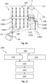
- Fig. 10 is a schematic perspective view of the system 1 having first and second assemblies 10a, 10b coupled with each other.
- the first assembly 10, 10a and the at least one second assembly 10b, 10c, 10d may be coupled with each other such that the first assembly 10, 10a is arranged at an angle ⁇ relative to the at least one second assembly 10b, 10c, 10d.
- the first assembly 10, 10a and the at least one second assembly 10b, 10c, 10d may be coupled with each other such that the first assembly 10, 10a is arranged perpendicular relative to the at least one second assembly 10b-d.
- the first assembly 10a may be arranged in a first plane E1 and the at least one second assembly 10b, 10c, 10d may be arranged in a second plane E2.
- the respective planes E1, E2 may be angled with respect to each other or parallel (but distanced).
- the assembly angle ⁇ may be defined between the first plane E1 and the second plane E2.
- Figs. 9A to 9E are schematic top views of the system 1 with various embodiments of processing units PU1-4 communicatively coupled with each other.
- Figs. 6A and 6B are only examples of communicatively coupling the respective assemblies 10a-d with each other to establish communication (e.g., of data) between the respective processing circuit boards 110a-d, and more specifically between respective processing units PU1-4.
- Figs. 9A to 9E illustrate different examples of how communication between the respective processing circuit boards 110a-d, and more specifically between the respective processing units PU1-4, can be established.
- Figs. 9A to 9E illustrate examples wherein four assemblies 10a-d (and respective processing circuit boards 110a-d) are provided. However, as already mentioned above, more or less processing circuit boards 110a-d may be provided.
- the first processing circuit board 110a may comprise at least one first processing unit PU1
- the second processing circuit board 110b may comprise at least one second processing unit PU2
- the third processing circuit board 110c may comprise at least one third processing unit PU3
- the fourth processing circuit board 110d may comprise at least one fourth processing unit PU4.
- the first processing unit PU1, the second processing unit PU2, the third processing unit PU3 and the fourth processing unit PU4 may be directly communicatively coupled with each other.
- each of the processing units PU1-PU4 may be communicatively coupled with each other, more specifically such that direct communication is formed between each of the processing units PU1-PU4 (in both ways).
- the assemblies 10a-d may be arranged as to form a 2x2 matrix.
- each processing unit PU1, PU2, PU3, PU4 may be directly communicatively coupled only with neighboring processing units PU1, PU2, PU3, PU4 (e.g., as also shown in the examples of Figs. 6A and 6B ).
- the assemblies 10a-d may be arranged as to form a 2x2 matrix.
- the first processing unit PU1 may be communicatively coupled with the second and third processing units PU2, PU3, more specifically such that direct communication is formed between the first processing unit PU1, the second processing unit PU2 and the third processing unit PU3.
- the fourth processing unit PU4 may not be a neighboring processing unit relative to the first processing unit PU1.
- the fourth processing unit PU4 may be indirectly, communicatively coupled with the first processing unit PU1 via the second and/or the third processing unit PU2, PU3. The same applies, vice versa, for the respective other ones. Thereby, several couplings (e.g., wireless connections or physical connectors) between the respective processing circuit boards 110a-d comprising the processing units PU1-4 can be reduced.
- each processing unit PU1-4 may be communicatively coupled with neighboring processing units PU1-4 such that it can transmit data to exactly one neighboring processing unit PU1-4 and receive data from exactly one other processing unit PU1-4.
- the connections between the neighboring processing units may be one-way.
- the first processing unit PU1 can only receive data from the third processing unit PU3 and can only transmit data to the second processing unit PU2. The same applies, vice versa, to the respective other processing units.
- connection or communication between the respective processing units PU1-4 may be provided by USART/UART, SPI and/or I2C.
- the method 300 may further comprise calibrating 340 the assembly 10 with a calibration device 40 as already describe above.
- the calibrating 340 may comprise: determining a location of the at least one sensing circuit board 130, more specifically of the at least one magnetometer 140, relative to the assembly 10.
- the set of geometric parameters may comprise predefined geometric parameters indicative of a geometric position and a geometric orientation of the magnetic object 20 relative to the user-borne device 2.
- the user-borne device location may be known.
- the method 200 may further comprise applying a filter for filtering the determined magnetic object location and/or the user-borne device location. Magnetic and electronic noise, as well as environmental variations may lead to non-smooth location determinations over time. Based on the filtering, a smooth location trajectory of the at least one magnetic object 20 relative to the reference coordinate system XYZ and/or to an interaction surface may be achieved.
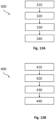
- Fig. 11 illustrates a process flow diagram of the method 200 according to the fifth aspect of the present disclosure.
- the method 200 comprises:
- each of the first assembly 10, 10a and the at least one second assembly 10, 10b-d may be an assembly 10 according to the first aspect of the present disclosure.
- the first assembly 10, 10a and the at least one second assembly 10, 10b-d may be of (or comprised with) a system 1 for tracking and/or determining a location of at least one magnetic object 20, more specifically of (or comprised with) a system 1 according to the second aspect of the present disclosure.
- Each of the assemblies 10a-d may comprise at least one processing unit PU1-4. At least one processing unit PU1-4 may be configured to execute the method 200 (or steps of the method).
- an external processing unit with which the system 1 is communicatively coupled may be configured to execute the method 200 (or steps of the method 200).
- the first magnetic field measurements may be generated with at least one first sensing circuit board 130a comprising at least one first magnetometer 140a of the first assembly 10a.
- the first magnetic field measurements may be collected with a first processing circuit board 110a comprising at least one first processing unit PU1 of the first assembly 10a.
- the second magnetic field measurements may be generated with at least one second sensing circuit board 130b comprising at least one second magnetometer 140b of the at least one second assembly 10b.
- the second magnetic field measurements may be collected with a second processing circuit board 110b comprising at least one second processing unit PU2 of the at least one second assembly 10b.
- At least one of the first and second processing units PU1, PU2 may be configured to determine the location of the at least one magnetic object 10.
- each processing unit PU1, PU2 may be configured to determine the location of the at least one magnetic object 20.
- only one or each of the first and second processing units may be configured to compute location data of the at least one magnetic object.
- the first and second processing units PU1, PU2 may perform magnetic field measurement and may transmit the data to an external processing unit which may be configured to determine the magnetic object location.
- Exchanging the collected magnetic field measurements may comprise the exchange or be in the form of (raw, i.e. non-processed) magnetic field measurements, magnetic field measurement data (e.g., processed magnetic field measurements), and/or magnetic object location data (which may be determined based on the magnetic field measurements).
- the method 200 may provide an improved tracking and/or determination of a location of at least one magnetic object 20 of a system 1, more specifically according to the second aspect of the present disclosure. Based on the method 200 as defined above, an error in location determination, in particular when the at least one magnetic object 20 moves from the first assembly 10a to the at least one second assembly 10b, can be reduced (see, e.g., Fig. 10 ).
- the respective assemblies 10a, 10b can share magnetic field measurements, associated measurement data and/or determined location data (which may be determined based on the magnetic field measurements and/or associated data) to determine a location of the magnetic object 20 with increased accuracy, even during transition of the magnetic object 20 from the first assembly 10a to the at least one second assembly 10b (especially in an edge area of the respective assemblies).
- a signal to noise ratio during measuring the magnetic field with the magnetometers 140, 150 can be increased thus leading to enhanced accuracy. Furthermore, since the respective assemblies 10a, 10b already receive the magnetic object location (data) from the respective other assembly, a time required for tracking the at least one magnetic object 20 may be reduced. By exchanging the magnetic field measurements, associated data and/or location data between the assemblies 10a, 10b-d, a sensing volume (and/or area) may be easily extended without reduced tracking and/or determination accuracy.
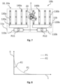
- FIG. 8 is a diagram showing an error in tracking and/or location determination of a system 1 as illustrated in Fig. 7 over a time.
- the horizontal axis t of the graph illustrates a time required to determine the magnetic object location and the vertical axis E of the graph illustrates an error in location determination that may occur during transition of the at least one magnetic object 20 from the first assembly 10a to the at least one second assembly 10b, or vice versa.
- the dotted graph P1 illustrates an error in magnetic object location determination over time, wherein the first assembly 10a and the second assembly 10b do not exchange magnetic field measurements, associated data and/or magnetic object location data. Particularly in initial sections of the time axis t the error is high, resulting in low accuracy of magnetic object location determination.
- the dashed graph P2 illustrates an error over time according to the method 200 of the present disclosure, wherein magnetic field measurements, associated data and/or magnetic object location data is exchanged between the first assembly 10a and the at least one second assembly 10b. Due to the exchanged measurements and/or data, the respective assemblies 10a, 10b can be initialized prior to and during transition of the at least one magnetic object 20 from the first assembly 10a to the at least one second assembly 10b, or vice versa. As a result, the error over time is very low, resulting in increased accuracy for magnetic object location determination even when the magnetic object 20 transitions from the first assembly 10a to the at least one second assembly 10b-d (and associated edge area).
- exchanging 230 comprises transmitting the collected first magnetic field measurements from the first assembly 10, 10a to the at least one second assembly 10b, 10c, 10d, and/or transmitting the collected second magnetic field measurements from the at least one second assembly 10b, 10c, 10d to the first assembly 10, 10a.
- each of the assemblies 10a-d may collect magnetic field measurements, may process magnetic field measurements to magnetic field measurement data, and may transmit the processed data to the respective other one of the first assembly 10a and the at least one second assembly 10b-d.
- Determining 240 a location of the at least one magnetic object 20 may be further based on first location data determined by the first assembly 10, 10a (more specifically the first processing unit PU1), wherein first location data is indicative of a location of the at least one magnetic object 20 relative to the first assembly (10, 10a), and/or second location data determined by the at least one second assembly 10b, 10c, 10d (more specifically the second processing unit PU2-4), wherein second location data is indicative of a location of the at least one magnetic object 20 relative to the at least one second assembly 10b, 10c, 10d.
- determining 240 a location of the at least one magnetic object 20 may comprise processing, with the first assembly 10, 10a, the first magnetic field measurements to first measurement data, determining, with the first assembly 10, 10a, first location data of the at least one magnetic object 20 based on the first measurement data, and transmitting the determined first location data from the first assembly 10, 10a to the at least one second assembly 10b, 10c, 10d.
- determining 240 a location of the at least one magnetic object 20 may comprise processing, with the at least one second assembly 10b, 10c, 10d, the second magnetic field measurements to second measurement data, determining, with the at least one second assembly 10b, 10c, 10d, second location data of the at least one magnetic object 20 based on the second measurement data, and transmitting the determined second location data from the at least one second assembly 10b, 10c, 10d to the first assembly 10, 10a.
- determining 240 a location of the at least one magnetic object 20 may comprise tracking the first location data and/or the second location data over a time period, predicting a movement and/or trajectory of the at least one magnetic object 20 relative to the first assembly 10, 10a and/or the at least one second assembly 10b, 10c, 10d based on the tracked first location data and/or second location data, and exchanging the predicted movement and/or trajectory of the at least one magnetic object 20 between the first assembly 10, 10a and the at least one second assembly 10b, 10c, 10d.
- the exchanged predicted movement and/or trajectory may be used only for initialization of the respective assembly 10a-d, e.g., before the magnetic object 20 is operated in the respective sensing volume (and/or area). Thereby, the error over time as described above can be kept very low, resulting in increased accuracy for magnetic object location determination.
- the method 200 may further comprise assuming a contact between the at least one magnetic object 20 or a user-borne device 2 comprising the at least one magnetic object 20 and an interaction surface on which the at least one magnetic object 20 or the user-borne device 2 is operable based on the determined magnetic object location.
- the housing(s) of the assembly 10 or the system 1 may define the interaction surface 210.
- the interaction surface may be provided on another device, e.g., a table or a board.
- Assuming a contact may comprise determining a contact event of the at least one magnetic object 20 or the user-borne device 2 comprising the at least one magnetic object 20 with the interaction surface.
- a specific change of the magnetic field strength and/or of the magnetic field form may be detected with the at least one magnetometer.
- the specific change may be indicative of a contact of the at least one magnetic object 20 or the user-borne device 2 comprising the at least one magnetic object 20 with the interaction surface.
- the method 200 may comprise representing 250 the at least one magnetic object 20 as virtual object on at least one output device 50 (see, e.g., Fig. 1 ) based on the determined location. More specifically a movement of the virtual object on the at least one output device 50 may be based on a virtual reproduction of the determined location of the at least one magnetic object 20, particularly relative to the first assembly 10, 10a and/or the at least one second assembly 10b, 10c, 10d.
- the user-borne device 2 may comprise the at least one magnetic object 20 and may be a writing and/or device.
- the assembly 10 or the system 1 may be coupled to a board, which may define an interaction surface.
- the writing device may be operated on the board, more specifically the interaction surface.
- a contact event of the writing device with the board may be determined and a location of the writing device (based on the determined magnetic object location over time) on the board may be represented as a virtual object in the form of written letters or sentences and/or drawing strokes (i.e., represented as digitized writing and/or drawing).
- the movement of the at least one magnetic object 20 within the sensing volume M may be caused by a manipulation of at least one magnetic object 20 or user-borne device 2 coupled with the at least one magnetic object 20 during a user operation.
- the movement of the at least one magnetic object 20 may be determined and reproduced as a movement of the virtual object on the output device 50.
- the visual reproduction may be a motion of a cursor on the output device.
- the visual reproduction may not be identical to the design of the at least one magnetic object 20 and/or user-borne device 2 but may be any icon (e.g., an arrow, a picture).
- the at least one output device 50 may be a display or a screen. The screen may be coupled with the at least one housing of the system 1 which may accommodate at least one or all of the assemblies 10a-d.
- the first assembly 10, 10a and/or the second assembly 10, 10b may comprise a plurality of magnetometers 140, 150.
- the method 200 may further comprise calibrating 260 the first assembly 10, 10a and/or the at least one second assembly (10, 10b) to determine a location and/or a distribution of the plurality of magnetometers 140, 150 relative to the first assembly 10, 10a and/or to the second assembly 10, 10b. More specifically, the location includes a position and/or an orientation of the plurality of magnetometers 140, 150 relative to the first assembly 10, 10a and/or to the second assembly 10, 10b.
- the plurality of magnetometers may comprise the magnetometers of the (at least one) sensing circuit board(s) and additional magnetometers 150.
- the first assembly 10, 10a may comprise a first plurality of magnetometers 140a, 150.
- Calibrating 260 may comprise obtaining first assembly data associated with the first assembly 10, 10a, wherein first assembly data includes dimension data and/or a location data of at least one first sensing circuit board 130a and/or at least one first connecting circuit board 120 relative to a first processing circuit board 110a, and determining, based on first assembly data, a location and/or a distribution of the first plurality of magnetometers 140a, 150 relative to the first assembly 10, 10a.
- the plurality of magnetometers 140, 150 may be arranged on the at least one sensing circuit board 130 and/or the at least one connecting circuit board 120.
- An arrangement of the respective magnetometers 140, 150 on the at least one sensing circuit board 130 and/or on the at least one connecting circuit board 120 may be known and obtained by the processing unit PU of the processing circuit board 110 by connecting the sensing circuit board(s) and the connecting circuit board(s) to the processing circuit board.
- the processing circuit board may comprise dimension data and/or location data of these magnetometers.
- the at least one second assembly 10, 10a may comprise a second plurality of magnetometers 140b, 150.
- Calibrating 260 may comprise obtaining second assembly data associated with the second assembly 10, 10b, wherein second assembly data includes dimension data and/or a location data of at least one second sensing circuit board 130b and/or at least one second connecting circuit board 120b relative to a second processing circuit board 110b, and determining, based on second assembly data, a location and/or a distribution of the second plurality of magnetometers 140b, 150 relative to the second assembly 10, 10b.
- calibrating 260 may further comprise determining, based on first assembly data, a location and/or a distribution of the first plurality of magnetometers 140a, 150 relative to the second assembly 10, 10b, and/or determining, based on second assembly data, a location and/or a distribution of the second plurality of magnetometers 140b, 150 relative to the first assembly 10, 10a.
- calibrating 260 may comprise obtaining location data associated with the first assembly 10, 10a and the second assembly 10b from a calibration device 40, wherein location data is indicative of a location of the first plurality of magnetometers 140a, 150 relative to the first assembly 10, 10a and of a location of the second plurality of magnetometers 140b, 150 relative to the second assembly (10b).
- calibrating 260 may comprise determining, based on the obtained location data, a location of the first plurality of magnetometers 140a, 150 relative to the second assembly 10b, and/or determining, based on the obtained location data, a location of the second plurality of magnetometers 140b, 150 relative to the first assembly 10, 10b.
- the method 200 as described above may be a computer-implemented method.
- a computer system may be configured to execute the computer-implemented method 200 as described above.
- a computer program may be configured to execute the computer-implemented method 200 as described above.
- a computer-readable medium or signal storing the computer program may be provided.
Landscapes
- Engineering & Computer Science (AREA)
- Remote Sensing (AREA)
- Physics & Mathematics (AREA)
- Life Sciences & Earth Sciences (AREA)
- Electromagnetism (AREA)
- Environmental & Geological Engineering (AREA)
- Geology (AREA)
- General Life Sciences & Earth Sciences (AREA)
- General Physics & Mathematics (AREA)
- Geophysics (AREA)
- Measuring Magnetic Variables (AREA)
Priority Applications (2)
| Application Number | Priority Date | Filing Date | Title |
|---|---|---|---|
| EP23219848.1A EP4575588A1 (fr) | 2023-12-22 | 2023-12-22 | Suivi magnétique à grande échelle |
| PCT/EP2024/085477 WO2025131880A1 (fr) | 2023-12-22 | 2024-12-10 | Suivi magnétique à grande échelle |
Applications Claiming Priority (1)
| Application Number | Priority Date | Filing Date | Title |
|---|---|---|---|
| EP23219848.1A EP4575588A1 (fr) | 2023-12-22 | 2023-12-22 | Suivi magnétique à grande échelle |
Publications (1)
| Publication Number | Publication Date |
|---|---|
| EP4575588A1 true EP4575588A1 (fr) | 2025-06-25 |
Family
ID=89321465
Family Applications (1)
| Application Number | Title | Priority Date | Filing Date |
|---|---|---|---|
| EP23219848.1A Pending EP4575588A1 (fr) | 2023-12-22 | 2023-12-22 | Suivi magnétique à grande échelle |
Country Status (2)
| Country | Link |
|---|---|
| EP (1) | EP4575588A1 (fr) |
| WO (1) | WO2025131880A1 (fr) |
Citations (7)
| Publication number | Priority date | Publication date | Assignee | Title |
|---|---|---|---|---|
| CN101846487A (zh) * | 2009-03-26 | 2010-09-29 | 曹宜 | 一种磁阵列位置传感装置及其定位方法 |
| US20150057969A1 (en) | 2012-03-29 | 2015-02-26 | Commissariat à I' énergie atomique et aux énergies alternatives | Method and device for locating a magnetic object |
| US20150323694A1 (en) * | 2014-05-07 | 2015-11-12 | Witricity Corporation | Foreign object detection in wireless energy transfer systems |
| CN209072450U (zh) * | 2018-11-27 | 2019-07-05 | 电卫士智能电器(北京)有限公司 | 电力设备开关及电力设备 |
| US20200116524A1 (en) | 2017-05-31 | 2020-04-16 | ISKn | Method for estimating the position of a magnet comprising a phase for identifying a magnetic disturbance |
| US20200191546A1 (en) * | 2018-12-13 | 2020-06-18 | Analog Devices International Unlimited Company | Magnetic position determination systems and methods |
| US20230301544A1 (en) * | 2020-08-04 | 2023-09-28 | Melzi Corporation | Metal detection device and methods of operation thereof |
-
2023
- 2023-12-22 EP EP23219848.1A patent/EP4575588A1/fr active Pending
-
2024
- 2024-12-10 WO PCT/EP2024/085477 patent/WO2025131880A1/fr active Pending
Patent Citations (7)
| Publication number | Priority date | Publication date | Assignee | Title |
|---|---|---|---|---|
| CN101846487A (zh) * | 2009-03-26 | 2010-09-29 | 曹宜 | 一种磁阵列位置传感装置及其定位方法 |
| US20150057969A1 (en) | 2012-03-29 | 2015-02-26 | Commissariat à I' énergie atomique et aux énergies alternatives | Method and device for locating a magnetic object |
| US20150323694A1 (en) * | 2014-05-07 | 2015-11-12 | Witricity Corporation | Foreign object detection in wireless energy transfer systems |
| US20200116524A1 (en) | 2017-05-31 | 2020-04-16 | ISKn | Method for estimating the position of a magnet comprising a phase for identifying a magnetic disturbance |
| CN209072450U (zh) * | 2018-11-27 | 2019-07-05 | 电卫士智能电器(北京)有限公司 | 电力设备开关及电力设备 |
| US20200191546A1 (en) * | 2018-12-13 | 2020-06-18 | Analog Devices International Unlimited Company | Magnetic position determination systems and methods |
| US20230301544A1 (en) * | 2020-08-04 | 2023-09-28 | Melzi Corporation | Metal detection device and methods of operation thereof |
Also Published As
| Publication number | Publication date |
|---|---|
| WO2025131880A1 (fr) | 2025-06-26 |
Similar Documents
| Publication | Publication Date | Title |
|---|---|---|
| US8711120B2 (en) | Single integrated circuit configured to operate both a capacitive proximity sensor device and a resistive pointing stick | |
| CN106257380A (zh) | 自适应力感测 | |
| RU2617270C1 (ru) | Катушка для визуализации методом магнитоиндукционной томографии | |
| CN105045445A (zh) | 用于噪声测量的驱动传感器电极 | |
| WO2023286065A1 (fr) | Géométrie de bobine pour un système de suivi électromagnétique | |
| Kubík et al. | Shielding effectiveness simulation of small perforated shielding enclosures using FEM | |
| EP2972440A1 (fr) | Système d'imagerie à champ magnétique | |
| EP3727623B1 (fr) | Système de jeu et procédé de détection de jouets | |
| Neto et al. | A soft tactile sensor based on magnetics and hybrid flexible-rigid electronics | |
| Malagò et al. | Magnetic position system design method applied to three-axis joystick motion tracking | |
| Wang et al. | A novel tangential electric-field sensor based on electric dipole and integrated balun for the near-field measurement covering GPS band | |
| EP4575588A1 (fr) | Suivi magnétique à grande échelle | |
| Jaeger et al. | Electromagnetic tracking using modular, tiled field generators | |
| Zeising et al. | Systematic performance evaluation of a novel optimized differential localization method for capsule endoscopes | |
| Pouchias et al. | Development of a flexible dielectric sensor for flow monitoring of the liquid resin infusion process | |
| CN111322937B (zh) | 磁性位置测定系统和方法 | |
| Gazizov et al. | Detection and localization of interference and useful signal extreme points in closely coupled multiconductor transmission line networks | |
| US11016602B2 (en) | Method for locating at least one movable magnetic object and associated system | |
| CN106292854B (zh) | 电子设备和控制方法 | |
| CN118695809A (zh) | 用于组织运动的磁检测的装置和方法 | |
| Tang et al. | Robust Current Sensing in Rectangular Conductors: Elliptical Hall-Effect Sensor Array Optimized via Bio-Inspired GWO-BP Neural Network | |
| Capriglione et al. | Accurate models for evaluating the direct conducted and radiated emissions from integrated circuits | |
| CN102878982A (zh) | 一种获取场景三维信息的方法和系统 | |
| Kumar et al. | More views of a one-sided surface: mechanical models and stereo vision techniques for Möbius strips | |
| Kang et al. | Analysis and visualization of the instantaneous spatial energy density and Poynting vector of the wireless power transfer system |
Legal Events
| Date | Code | Title | Description |
|---|---|---|---|
| PUAI | Public reference made under article 153(3) epc to a published international application that has entered the european phase |
Free format text: ORIGINAL CODE: 0009012 |
|
| STAA | Information on the status of an ep patent application or granted ep patent |
Free format text: STATUS: THE APPLICATION HAS BEEN PUBLISHED |
|
| AK | Designated contracting states |
Kind code of ref document: A1 Designated state(s): AL AT BE BG CH CY CZ DE DK EE ES FI FR GB GR HR HU IE IS IT LI LT LU LV MC ME MK MT NL NO PL PT RO RS SE SI SK SM TR |
|
| STAA | Information on the status of an ep patent application or granted ep patent |
Free format text: STATUS: REQUEST FOR EXAMINATION WAS MADE |
|
| 17P | Request for examination filed |
Effective date: 20251219 |