EP4575656A1 - Uhrwerk, das eine reguliervorrichtung umfasst - Google Patents
Uhrwerk, das eine reguliervorrichtung umfasst Download PDFInfo
- Publication number
- EP4575656A1 EP4575656A1 EP23218454.9A EP23218454A EP4575656A1 EP 4575656 A1 EP4575656 A1 EP 4575656A1 EP 23218454 A EP23218454 A EP 23218454A EP 4575656 A1 EP4575656 A1 EP 4575656A1
- Authority
- EP
- European Patent Office
- Prior art keywords
- winding wheel
- wheel
- energy source
- control cam
- anchor
- Prior art date
- Legal status (The legal status is an assumption and is not a legal conclusion. Google has not performed a legal analysis and makes no representation as to the accuracy of the status listed.)
- Withdrawn
Links
Images



Classifications
-
- G—PHYSICS
- G04—HOROLOGY
- G04B—MECHANICALLY-DRIVEN CLOCKS OR WATCHES; MECHANICAL PARTS OF CLOCKS OR WATCHES IN GENERAL; TIME PIECES USING THE POSITION OF THE SUN, MOON OR STARS
- G04B1/00—Driving mechanisms
- G04B1/10—Driving mechanisms with mainspring
- G04B1/22—Compensation of changes in the motive power of the mainspring
- G04B1/225—Compensation of changes in the motive power of the mainspring with the aid of an interposed power-accumulator (secondary spring) which is always tensioned
-
- G—PHYSICS
- G04—HOROLOGY
- G04B—MECHANICALLY-DRIVEN CLOCKS OR WATCHES; MECHANICAL PARTS OF CLOCKS OR WATCHES IN GENERAL; TIME PIECES USING THE POSITION OF THE SUN, MOON OR STARS
- G04B17/00—Mechanisms for stabilising frequency
- G04B17/20—Compensation of mechanisms for stabilising frequency
- G04B17/26—Compensation of mechanisms for stabilising frequency for the effect of variations of the impulses
-
- G—PHYSICS
- G04—HOROLOGY
- G04B—MECHANICALLY-DRIVEN CLOCKS OR WATCHES; MECHANICAL PARTS OF CLOCKS OR WATCHES IN GENERAL; TIME PIECES USING THE POSITION OF THE SUN, MOON OR STARS
- G04B21/00—Indicating the time by acoustic means
- G04B21/02—Regular striking mechanisms giving the full hour, half hour or quarter hour
- G04B21/027—Regular striking mechanisms giving the full hour, half hour or quarter hour with locking wheel
-
- G—PHYSICS
- G04—HOROLOGY
- G04B—MECHANICALLY-DRIVEN CLOCKS OR WATCHES; MECHANICAL PARTS OF CLOCKS OR WATCHES IN GENERAL; TIME PIECES USING THE POSITION OF THE SUN, MOON OR STARS
- G04B21/00—Indicating the time by acoustic means
- G04B21/02—Regular striking mechanisms giving the full hour, half hour or quarter hour
- G04B21/06—Details of striking mechanisms, e.g. hammer, fan governor
-
- G—PHYSICS
- G04—HOROLOGY
- G04B—MECHANICALLY-DRIVEN CLOCKS OR WATCHES; MECHANICAL PARTS OF CLOCKS OR WATCHES IN GENERAL; TIME PIECES USING THE POSITION OF THE SUN, MOON OR STARS
- G04B23/00—Arrangements producing acoustic signals at preselected times
- G04B23/02—Alarm clocks
- G04B23/023—Driving, e.g. by springs or common drive with the clockwork; gears; escapements
Definitions
- the present invention relates to a watch movement comprising an energy source, intended to deliver a driving force to a train, and a device for regulating the driving force arranged downstream of the energy source, said regulating device comprising a winding wheel arranged to be able to be driven by the energy source periodically during normal operation of the movement, an output wheel arranged to power the train, at least one control wheel set comprising a control cam secured to a control wheel kinematically connected to the output wheel, a device for locking the winding wheel controlled by said control cam to block said winding wheel and release it periodically, and an elastic member comprising a first end secured to the winding wheel and a second end secured to the output wheel, said elastic member being arranged to be wound periodically by storing energy supplied by the energy source when said winding wheel is released by the locking device, and to restore the energy to the output wheel by disarming itself when said winding wheel is blocked by the locking device.
- the present invention also relates to a timepiece comprising such a watch movement.
- the expression “regulating device” also called “constant force device” typically refers to a mechanism interposed in the going train connecting the energy source to the escapement and comprising a permanently charged intermediate spring, in order to transmit to the escapement a relatively constant torque, corresponding to the tension of the intermediate spring.
- the constant force device temporarily blocks the part of the going train located upstream, then periodically releases it to re-tension the intermediate spring.
- the device for locking the winding wheel comprises a single anchor controlled by a control cam, said anchor being provided with two pallets cooperating alternately with the winding wheel to block or release it periodically.
- Another disadvantage of the embodiments is the lack of unlocking torque management and its imbalance. This does not allow for balanced consumption between the input and output of the constant force device. Another disadvantage is that each of the known constant force devices has its own efficiency.
- constant force systems are not self-starting. Some constant force systems can be self-starting but do not allow the full power reserve to be used. Indeed, the presence of the spring element of the constant force device, between the barrel and the balance, causes the movement to stop when the force of the barrel spring is no longer sufficient to wind the spring of the constant force device. This has the effect of not being able to use the full power reserve.
- the present invention aims to remedy at least in part these drawbacks by proposing a watch movement comprising a regulating or constant force device which makes it possible to deliver at the output, for example to the regulating organ, the smoothest possible torque and which thus makes it possible to compensate for variations in torque of the energy source and, where appropriate, that of the finishing gear, while proposing a system which has improved operating safety.
- this system can also be self-starting and can also have optimized consumption making it possible to use the entire power reserve.
- the invention relates to a watch movement comprising a power source, intended to deliver a driving force to a gear train, for example to maintain the oscillating movement of a regulating organ via a finishing gear train or to power the striking gear train typically of a minute repeater, and a device for regulating the driving force arranged downstream of the power source, for example between the power source and the escapement associated with the regulating organ or between the power source and the striking regulator.
- Said regulating device comprises a winding wheel arranged to be able to be driven by the energy source periodically during normal operation of the movement, an output wheel arranged to power the gear train, at least one control wheel set comprising a control cam secured to a control wheel kinematically connected to the output wheel, a device for locking the winding wheel controlled by said control cam to block said winding wheel and release it periodically, and an elastic member comprising a first end secured to the winding wheel and a second end secured to the output wheel.
- Said elastic member is arranged to be wound periodically by storing energy supplied by the energy source when said winding wheel is released by the locking device, and to restore the energy to the output wheel by disarming itself when said winding wheel is blocked by the locking device.
- the locking device comprises two anchors distinct from one another, each being arranged to follow the profile of the control cam in order to cooperate or not with the winding wheel, said profile of the control cam comprising an alternation of lifts and hollows configured to control said anchors so that one can block then release the winding wheel alternately with the other.
- the winding wheel comprises teeth each having a resting plane and the anchors are arranged relative to the winding wheel so as to be able to be in contact with a resting plane of a tooth of said winding wheel to block it so that said winding wheel works with each of the anchors at rest with outgoing friction.
- This allows the mechanism to be much less sensitive to friction, which makes the system more robust, or even improves its performance.
- the lifts of the control cam are configured so that the pressure angle of an anchor on the control cam is greater than 10°.
- This particular geometry of the control cam allows the mechanism of the invention to be self-starting.
- the output wheel comprises at least one drive means arranged to be able to cooperate with the winding wheel in order to simultaneously drive said winding wheel and said output wheel at the same speed when the energy supplied by the energy source is no longer sufficient to wind the elastic member.
- This makes it possible to have a mechanism which operates even when the torque of the energy source is no longer sufficient to wind the regulating device. It is thus possible to benefit from the entire power reserve of the movement.
- the present invention also relates to a timepiece comprising a watch movement as defined above.
- the present invention relates to a watch movement comprising an energy source intended to deliver a driving force to a train.
- This train may be any type of train such as a striking train or a finishing train as taken as an example in the preferred embodiment which is illustrated by the appended figures and which will be described below.
- This energy source could thus maintain the oscillating movement of a regulating organ via a finishing train and an escapement associated with the regulating organ, or power a striking mechanism, in particular a minute repeater via the striking train.
- the watch movement of the present invention further comprises a regulating device or constant force device arranged downstream of the energy source, for example between the source energy source and the escapement or between the energy source and the striking regulator.
- the energy source is for example a barrel but could be any energy source capable of providing driving torque.
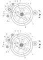
- said regulating device 1 comprises a winding wheel 2 in the form of a toothed crown connected to a central hub of center A by two radial arms 3, 4 whose role will be described below.
- the winding wheel 2 is arranged to be able to be driven by the energy source periodically during normal operation of the movement, that is to say when the energy source has sufficient energy to wind the regulating device 1.
- the winding wheel 2 is coaxial and integral with an input pinion 5 rotatably mounted on the frame of the watch movement around an axis passing through the center of rotation A.
- the input pinion 5 is arranged to be kinematically connected to the energy source via elements of the finishing gear train provided between said input pinion 5 and the energy source.
- the winding wheel 2 is arranged to be able to rotate clockwise.
- the winding wheel 2 is provided, on the outer periphery of its crown, with teeth 6 each having, at the front in the direction of rotation of the winding wheel 2, an inclined plane constituting a rest plane 6a and, at the rear in the direction of rotation of the winding wheel 2, a radial plane 6b.
- the angle between the radial plane 6b and the inclined rest plane 6b is approximately 45° in the trigonometric direction.
- the role of the rest planes 6a will be detailed below.
- the regulating device 1 also comprises an output wheel 8 arranged to control the escapement.
- the output wheel 8 is mounted freely on the axis passing through the center of rotation A, coaxially with the winding wheel 2.
- the output wheel 8 is arranged under the winding wheel 2 as seen in the drawings and has a diameter greater than that of the winding wheel 2.
- the output wheel 8 is kinematically connected to the escapement via elements of the finishing gear train provided between said output wheel 8 and the escapement.
- the output wheel 8 comprises an external peripheral toothing 8a meshing for example with a pinion 10 of the finishing gear train.
- a pinion 10 could be replaced directly by the escapement pinion or by a gear train located downstream of the regulating device. 1 said constant force.
- the toothing 8a is provided on the periphery of a crown connected to a central hub of center A by means of radial arms 9.
- the output wheel 8 is arranged to rotate clockwise.
- the regulating device 1 also comprises at least one control wheel 12 comprising a control cam 14 secured to a control wheel 16 kinematically connected to the output wheel 8.
- the control wheel 12 is rotatably mounted on the frame of the movement around an axis passing through the center of rotation B and is arranged so that the control wheel 16 meshes with the outer peripheral toothing 8a of the output wheel 8.
- the control wheel 12 is rotated counterclockwise by the output wheel 8.
- the control cam 14 is arranged at the height of the winding wheel 2 and has a specific profile described below.
- the regulating device 1 also comprises a device for locking the winding wheel 2 controlled by said control cam 14 to periodically block and release said winding wheel 2, and which will be described in detail below.
- an elastic member 18 comprising a first end secured to the winding wheel 2 and a second end secured to the output wheel 8.
- the elastic member 18 is constituted by a leaf spring secured at one end to the winding wheel 2 and at the other end to the output wheel 8.
- a leaf spring could be fixed by one end to the radial arm 4 of the winding wheel 2 and by the other end to a pin (not shown) secured to the output wheel 8.
- This elastic member 18 can be a part in its own right or be integrated into at least one of the parts that it connects. It may in particular constitute a part of the winding wheel 2, as illustrated in the figures, or a part of the output wheel 8.
- Said elastic member 18 is arranged to be compressed periodically in order to store the energy supplied by the energy source when the winding wheel 2 released by the locking device is driven in rotation by the input pinion 5, and to restore the energy to the output wheel 8 by relaxing when said winding wheel 2 is blocked by the locking device.
- the force of the elastic member 18 is sized according to the application for which the constant force regulating device 1 is intended and/or according to of the location where this device is located between the energy source and the oscillator or regulator.
- the constant force device is located close to the energy source, i.e. upstream of the gear train, it will have to be sized so as to be able to provide a more powerful torque than if it were intended to be placed downstream of the gear train, for example shortly before the oscillator associated with the escapement or the regulator in the case of a striking mechanism.
- the locking device comprises a first anchor 20 and a second anchor 22 distinct from each other.
- the first anchor 20 is rotatably mounted on the frame of the watch movement around an axis passing through the center of rotation C and the second anchor 22 is rotatably mounted on the frame of the watch movement around an axis passing through the center of rotation D.
- Each anchor 20, 22 is arranged to, on the one hand, follow the profile of the control cam 14 in order, on the other hand, to cooperate or not with the winding wheel 2 to block it, respectively release it.
- the profile of the control cam 14 comprises an alternation of lifts 24 and hollows 26 configured to control said anchors 20, 22 so that one can successively block then release the winding wheel 2 alternately with the other.
- the lifts 24 and the hollows 26 are configured so that, as long as an anchor 20, 22 is in contact with a lift 24, said anchor 20, 22 is immobilized in contact with the winding wheel 2 and so that when an anchor 20, 22 is in contact with a hollow 26, said anchor 20, 22 is not in contact with the winding wheel 2 and can pivot around its axis.
- the lifts 24 and the hollows 26 are distributed on the profile of the control cam 14 so that when one of the anchors 20, 22 is in contact with a lift 24, the other anchor 20, 22 is in contact with a hollow 26.
- the profile of the control cam 14 is configured to control the first and second anchors 20, 22 so that one of the anchors 20, 22 is approaching the winding wheel 2 while the other anchor 20, 22 is in contact with said winding wheel 2 so that said one of the anchors 20, 22 comes into contact with the winding wheel 2 after the other anchor has released said winding wheel 2.
- the lifts 24 and the hollows 26 are configured so that, when one of the anchors 20, 22 engages on the entrance of a lift 24, follows said lift 24, arrives at the exit of said lift 24, while blocking the winding wheel 2, and engages on the entrance of the adjacent hollow 26 having released said winding wheel 2, which defines a blocking and releasing cycle, in a synchronized manner the other anchor 20, 22 engages on the entrance of a hollow 26, follows said hollow 26, arrives at the exit of said hollow 26, approaching the winding wheel 2, and engages on the entrance of the adjacent lift 24 in order to in turn block the winding wheel 2.
- the first and second anchors 20, 22 are arranged relative to the winding wheel 2 so as to be able to be in contact with a rest plane 6a of a tooth 6 of said winding wheel 2, when said winding wheel 2 is blocked, so that said winding wheel 2 works with each of the first and second anchors 20, 22 in rest with outgoing friction.
- outgoing friction means that the winding wheel 2 and the anchors 20, 22 are arranged relative to each other so that the pressure angles between the winding wheel 2 and the anchor 20, 22 in contact are favorable to the release of the anchor when the winding wheel rotates in the chosen direction, here the clockwise direction.
- the pressure angles, on the one hand between the winding wheel and the anchor 20 and on the other hand between the winding wheel and the anchor 22, are configured to be balanced, making this system independent of the coefficients of friction.
- the winding wheel 2 presses said anchor 20, 22 via the rest plane 6a of one of its teeth 6 with a tendency to move said anchor 20, 22 away from the center line connecting the center of rotation C or D of the anchor 20 or 22 and the center of rotation A of the winding wheel 2.
- the regulating device 1 is much less sensitive to friction than known devices, and therefore has better efficiency.
- the first and second anchors 20, 22 are arranged on each side of a line connecting the center of rotation B of the control wheel and the center of rotation A of the winding wheel 2.
- the first anchor 20 comprises a single arm pivotally mounted at C by one end, and provided at its other free end of a head 27 which has, on the side of the winding wheel 2, a beak 28, and on the side of the control cam 14, a point 30.
- the beak 28 is arranged to be able to cooperate with the rest plane 6a of a tooth 6 of the winding wheel 2 when said winding wheel 2 is blocked by the first anchor 20, and the point 30 is arranged to follow the profile of the control cam 14 when said control cam 14 is driven in rotation.
- the second anchor 22 comprises two arms 22a, 22b extending on either side of its center of rotation D.
- One of said arms 22a is provided at its free end with a beak 32 arranged to be able to cooperate with the rest plane 6a of a tooth 6 of the winding wheel 2 when said winding wheel 2 is blocked by the second anchor 22.
- the other arm 22b is provided at its free end with a point 34 following the profile of the control cam 14 when said control cam 14 is driven in rotation.
- the first anchor 20 is arranged upstream of the control cam 14 relative to the direction of rotation of the winding wheel 2, its head 27 being positioned between the winding wheel 2 and the control cam 14 near the shortest distance between said winding wheel 2 and said control cam 14.
- the first and second anchors 20, 22 are configured so that the moments of the reaction forces exerted by said anchors 20, 22 bearing on the rest plane 6a of the teeth 6 of the winding wheel 2 are equal.
- the lifts of the control cam 14 are configured so that the pressure angle ⁇ of an anchor 20, 22 on the control cam 14 is greater than 10°, and preferably between 13° and 27°, and preferably of the order of 15°, typically depending on the materials present.
- Such a favorable pressure angle ⁇ makes it possible to never block the mechanism and to have a regulating device which is self-starting in the event of winding of the barrel constituting the energy source after a stoppage of the watch movement.
- the tension of the elastic member 18 is also influenced by the barrel torque. During each winding and unwinding cycle of the elastic member 18, this tension varies in a range extending between a high value and a low value.
- the geometry of the control cam 14 and that of the winding wheel 2 are preferably configured so that the range of variation of the tension of the elastic member 18 is low, preferably as low as possible, or even zero in a particular configuration in which operational safety would then be lost.
- the anchors release the winding wheel 2 for a short time interval which is preferably as short as possible.
- This time interval can be translated by an angular value of displacement of the winding wheel 2, an angular value which can typically be of the order of 2°.
- the winding wheel 2 moves of the order of 6° during a cycle covering both the winding and the unwinding of the elastic member 18.
- the winding phase typically operates during an angular displacement of 4°, thus leaving the unwinding phase with a displacement of the order of only 2°.
- These angular values are a function of the geometry of the control cam 14 and that of the winding wheel 2.
- the winding wheel 2 rotates slightly less quickly than the output wheel 8, which precisely allows the winding wheel 2 to be wound via the elastic member 18.
- the elastic member 18 is arranged so as not to be completely disarmed when the winding wheel 2 is released, which makes it possible to maintain operational safety.
- the output wheel 8 carries at least one drive means, such as a pin 36 arranged on at least one of the radial arms 9 to be able to cooperate with the winding wheel 2 in order to secure said winding wheel 2 and said output wheel 8 which catches up with the winding wheel 2 when the torque provided by the energy source, which is typically a barrel, is no longer sufficient to wind the elastic member 18.
- a pin 36 could be replaced by any other mechanical means making it possible to achieve cooperation between the output wheel 8 and the winding wheel 2.
- the driving of winding wheel 2 by the output wheel is carried out simultaneously at the same speed, typically by contact between these two wheels without one necessarily being secured to the other.
- the energy source weakens and drives the winding wheel 2 with the elastic member 18, the latter finishes disarming, so that the output wheel 8 catches up with the winding wheel 2, and they become solid thanks to the pin 36 or one of the pins 36 of the output wheel 8 in contact with the lower face of the arm 3 of the winding wheel 2.
- the winding wheel 2 and the output wheel 8 then rotate together at the same speed and transmit the remaining energy from the energy source to the escapement.
- the anchors 20, 22 and the control cam 14 are simply freely driven by the output wheel 8, so that there are no longer any intentional constraints between the anchors 20, 22 and the control cam 14 or the winding wheel 2; only simple friction remains due to the sliding of the anchors on the surfaces in play of these elements.
- the elastic member 18 is armed.
- the winding wheel 2 is blocked by the beak 28 of the first anchor 20 resting on the rest plane 6a of the tooth 6 of the winding wheel 2, the rest being done by outgoing friction, as defined above.
- the point 30 of the first anchor 20 is positioned on the entrance of the lift 24 of the control cam 14.
- the point 34 of the second anchor 22 is located at the entrance of the hollow 26 of the cam of command 14, the beak 32 of the second anchor 22 having just left the tooth 6' and released the winding wheel 2 during the previous cycle.
- the output wheel 8 is driven to rotate regularly in a clockwise direction due to the disarming of the wound elastic member 18 during the release of the winding wheel 2 by the second anchor 22 during the previous cycle.
- the rotation of the output wheel 8 drives the rotation of the pinion 10 to power the elements of the finishing gear train up to the regulating member.
- the rotation of the output wheel 8 also drives the rotation of the control wheel 16 and therefore of the control cam 14 in the counterclockwise direction.
- the output wheel 8 continues to rotate clockwise.
- the control cam 14 continues to rotate counterclockwise so that the tip 30 of the first anchor 20 follows the lift 24, the beak 28 remaining in abutment on the resting plane 6a of the tooth 6 of the winding wheel 2 in order to control its position by keeping it blocked.
- the tip 34 of the second anchor 22 follows the hollow 26 by heading towards the adjacent lift 24' so that the second anchor 22 pivots around its axis D in the clockwise direction to begin to position itself for the next cycle, its beak 32 beginning to approach the adjacent tooth 6" of the winding wheel 2.
- the output wheel 8 continues to rotate clockwise, the control cam 14 continuing its rotation in the counterclockwise direction.
- the tip 30 of the first anchor 20 continues to follow the lift 24 while heading towards its exit, the beak 28 remaining in support on the rest plane 6a of the tooth 6 of the winding wheel 2 to keep it blocked, the rest always being done with outgoing friction.
- the tip 34 of the second anchor 22 follows the hollow 26 while approaching its exit so that the second anchor 22 continues to pivot around its axis D, its beak 32 continuing to approach the tooth 6" of the winding wheel 2.
- the output wheel 8 continues to rotate clockwise, the control cam 14 continuing its rotation counterclockwise.
- the tip 30 of the first anchor 20 arrives at the exit of the lift 24 so that said first anchor 20 is about to fall into the adjacent hollow 26', this which will have the effect of releasing the winding wheel 2, the first anchor 20 being released from the resting plane 6a of the tooth 6.
- the second anchor 22 arrives at the exit of the hollow 26 at the junction of the lift 24' so that its beak 32 comes to position itself close to the resting plane 6a" of the tooth 6" and is ready to block the winding wheel 2 as soon as the latter has turned clockwise after having been released by the first anchor 20.
- This cycle of blocking and releasing the winding wheel 2 carried out by the first anchor 20 ends with the release of said winding wheel 2 when the first anchor 20 falls into the hollow 26' of the control cam 14 and pivots around its axis C in the counterclockwise direction to disengage from the rest plane 6a of the tooth 6 of the winding wheel 2.
- the winding wheel 2 thus released is driven in rotation in the clockwise direction by the input pinion 5, which has the effect of winding the elastic member 18 again.
- the winding wheel 2 rotates clockwise until the resting plane 6a" of the tooth 6" comes into contact with the beak 32 of the second anchor 22 which has been positioned for this purpose beforehand by following the hollow 26 as described above.
- the winding wheel 2 is then blocked again but by the second anchor 22 so that a new blocking and release cycle begins, but carried out by the second anchor 22.
- the beak 32 of the second anchor 22 blocks the winding wheel 2, said beak 32 being supported on the rest plane 6a" of the tooth 6" of the winding wheel 2, the rest being done with outgoing friction, as defined above.
- the point 34 of the second anchor 22 is positioned on the entry of the lift 24' of the control cam 14.
- the point 30 of the first anchor 20 is located at the entry of the hollow 26' of the control cam 14, the beak 28 of the first anchor 20 having just left the tooth 6 and released the winding wheel 2 during the previous cycle described above.
- the output wheel 8 continues to rotate clockwise.
- the control cam 14 continues to rotate counterclockwise so that the tip 34 of the second anchor 22 follows the lift 24', the beak 32 remaining in contact with the rest plane 6a" of the tooth 6" of the winding wheel 2 in order to control its position by keeping it blocked.
- the tip 30 of the first anchor 20 follows the hollow 26' so that the first anchor 20 pivots around its axis C clockwise to begin positioning itself for the next cycle, its beak 28 beginning to approach the adjacent tooth 6'" of the winding wheel 2.
- the output wheel 8 continues to rotate clockwise, the control cam 14 continuing its rotation counterclockwise.
- the point 34 of the second anchor 22 continues to follow the lift 24' while heading towards its exit, the beak 32 remaining in support on the rest plane 6a" of the tooth 6" of the winding wheel 2 to keep it blocked, the rest always being done with outgoing friction.
- the point 30 of the first anchor 20 follows the hollow 26' while approaching its exit so that the first anchor 20 continues to pivot around its axis C, its beak 28 continuing to approach the tooth 6′′′ of the winding wheel 2.
- the output wheel 8 continues to rotate clockwise, the control cam 14 continuing its rotation in the counterclockwise direction.
- the tip 34 of the second anchor 22 arrives at the exit of the lift 24' so that said second anchor 22 is about to fall into the adjacent hollow, which will have the effect of releasing the winding wheel 2, the second anchor 22 being released from the resting plane 6a" of the tooth 6".
- the first anchor 20 arrives at the exit of the hollow 26' adjoining a lift so that its beak 28 comes to position itself close to the resting plane of the tooth 6"' and is ready to block the winding wheel 2 as soon as the latter has rotated clockwise after having been released by the second anchor 22.
- This cycle of blocking and releasing the winding wheel 2 carried out by the second anchor 22 ends with the release of said winding wheel 2 when the second anchor 22 falls into the next hollow of the control cam 14 and pivots around its axis D in the counterclockwise direction to disengage from the rest plane 6a" of the tooth 6" of the winding wheel 2.
- the winding wheel 2 thus released is driven in rotation in the clockwise direction by the input pinion 5, which has the effect of re-winding the elastic member 18.
- a new cycle of blocking and releasing carried out by the first anchor 20 as described above begins again, and so on.
- the regulating device used in the watch movement according to the invention makes it possible to deliver a torque to the regulating organ as smooth as possible and thus to compensate for variations in the torque of the power source and that of the finishing gear, while offering a system that offers improved operating safety.
- the use of two separate anchors advantageously allows the input and output of a standard anchor to be decoupled and the operating sequences to be optimized.
- the use of two separate anchors also advantageously allows the mechanism to always work at rest with outgoing friction, thus significantly reducing the friction between each of the anchors and the teeth of the winding wheel. This improves the efficiency of the mechanism and optimizes consumption.
- control cam 14 and in particular of the lifts 24 configured to have favorable pressure angles between the anchors 20, 22 and the control cam 14, allows the regulating device used in the watch movement according to the invention to be self-starting in the event of winding of the energy source after a stoppage of the watch movement.
- the regulating device used in the watch movement according to the invention also makes it possible to use the entire power reserve.
- the gear train is a finishing gear train
- the energy source is intended to maintain the oscillating movement of a regulating member by means of said finishing gear train and a regulating member
- the regulating device 1 is arranged between the energy source and the escapement.
- the energy source is typically in this case a barrel.
- the gear train is a striking gear train
- the energy source is intended to power a striking mechanism, preferably of the minute repeater type, via said striking mechanism and a striking regulator
- the regulating device 1 is arranged between the energy source and the striking regulator.
- the energy source is typically in this case a striking barrel.
- the invention is not limited to the example described.
- the embodiment described above suggests an arrangement of the winding wheel 2, anchors 20, 22 and the control cam 14 in the same plane to benefit from a minimum thickness, it could nevertheless be possible to superimpose at least part of its elements, for example to arrange them on the same axis or to arrange the control cam coaxially with a mobile such as the pinion 10.
- the regulating device comprises a control wheel set 12 and therefore a control cam 14. It would also be possible to provide, according to another embodiment, two control wheels and therefore two control cams, synchronized with respect to each other, configured so that each of them can actuate one of the two anchors, and arranged appropriately to work at rest with outgoing friction for each anchor.
Landscapes
- Physics & Mathematics (AREA)
- General Physics & Mathematics (AREA)
- Acoustics & Sound (AREA)
- Transmission Devices (AREA)
- Electromechanical Clocks (AREA)
Priority Applications (3)
| Application Number | Priority Date | Filing Date | Title |
|---|---|---|---|
| EP23218454.9A EP4575656A1 (de) | 2023-12-20 | 2023-12-20 | Uhrwerk, das eine reguliervorrichtung umfasst |
| CN202480080910.7A CN122497921A (zh) | 2023-12-20 | 2024-12-12 | 包括调节装置的钟表机芯 |
| PCT/EP2024/086038 WO2025132019A1 (fr) | 2023-12-20 | 2024-12-12 | Mouvement horloger comprenant un dispositif de regulation |
Applications Claiming Priority (1)
| Application Number | Priority Date | Filing Date | Title |
|---|---|---|---|
| EP23218454.9A EP4575656A1 (de) | 2023-12-20 | 2023-12-20 | Uhrwerk, das eine reguliervorrichtung umfasst |
Publications (1)
| Publication Number | Publication Date |
|---|---|
| EP4575656A1 true EP4575656A1 (de) | 2025-06-25 |
Family
ID=89224610
Family Applications (1)
| Application Number | Title | Priority Date | Filing Date |
|---|---|---|---|
| EP23218454.9A Withdrawn EP4575656A1 (de) | 2023-12-20 | 2023-12-20 | Uhrwerk, das eine reguliervorrichtung umfasst |
Country Status (3)
| Country | Link |
|---|---|
| EP (1) | EP4575656A1 (de) |
| CN (1) | CN122497921A (de) |
| WO (1) | WO2025132019A1 (de) |
Citations (3)
| Publication number | Priority date | Publication date | Assignee | Title |
|---|---|---|---|---|
| EP2166419A1 (de) | 2008-09-18 | 2010-03-24 | Agenhor SA | Uhrwerk, das eine Konstantkraftvorrichtung aufweist |
| CH707593A2 (fr) * | 2013-02-15 | 2014-08-15 | Le Cercle Des Horlogers Sa | Pièce d'horlogerie. |
| CH712101A2 (fr) | 2016-02-08 | 2017-08-15 | Hepta Swiss Sa | Mouvement d'horlogerie comprenant un dispositif de régulation disposé entre une source d'énergie et un échappement. |
-
2023
- 2023-12-20 EP EP23218454.9A patent/EP4575656A1/de not_active Withdrawn
-
2024
- 2024-12-12 WO PCT/EP2024/086038 patent/WO2025132019A1/fr active Pending
- 2024-12-12 CN CN202480080910.7A patent/CN122497921A/zh active Pending
Patent Citations (4)
| Publication number | Priority date | Publication date | Assignee | Title |
|---|---|---|---|---|
| EP2166419A1 (de) | 2008-09-18 | 2010-03-24 | Agenhor SA | Uhrwerk, das eine Konstantkraftvorrichtung aufweist |
| CH707593A2 (fr) * | 2013-02-15 | 2014-08-15 | Le Cercle Des Horlogers Sa | Pièce d'horlogerie. |
| CH712101A2 (fr) | 2016-02-08 | 2017-08-15 | Hepta Swiss Sa | Mouvement d'horlogerie comprenant un dispositif de régulation disposé entre une source d'énergie et un échappement. |
| EP3208662A1 (de) * | 2016-02-08 | 2017-08-23 | Hepta Swiss SA | Uhrwerk, das eine reguliervorrichtung umfasst |
Also Published As
| Publication number | Publication date |
|---|---|
| WO2025132019A1 (fr) | 2025-06-26 |
| CN122497921A (zh) | 2026-07-31 |
Similar Documents
| Publication | Publication Date | Title |
|---|---|---|
| EP2166419B1 (de) | Uhrwerk, das eine Konstantkraftvorrichtung aufweist | |
| EP2548084B1 (de) | Uhrwerk mit ausgleichendem aufziehmechanismus | |
| EP3059643B1 (de) | Uhrmechanismus | |
| EP2541346B1 (de) | Vorrichtung zum Zurückstellen eines Anzeigeorgans für eine mit der Zeit zusammenhängenden Größe in eine voreingestellte Position | |
| EP3599516B1 (de) | Retrogrades tourbillon oder karussell eines uhrwerks | |
| EP3059642B1 (de) | Uhrmechanismus | |
| EP3306416B1 (de) | Mechanisches uhrwerk mit erfassung der gangreserve | |
| WO2018046563A1 (fr) | Mecanisme d'echappement | |
| EP3599517A1 (de) | Retrogrades tourbillon oder karussell eines uhrwerks | |
| EP3770696A1 (de) | Anschlagkäfig für uhr mit aufzugstift und anschlagstift | |
| WO2025132019A1 (fr) | Mouvement horloger comprenant un dispositif de regulation | |
| EP3584641B1 (de) | Selbststartende und gesicherte chronometerhemmung für uhren | |
| EP3623875B1 (de) | Uhrhemmungsmechanismus mit bistabiler blattfeder | |
| EP4405756B1 (de) | Uhrwerk | |
| CH706543A2 (fr) | Mécanisme d'échappement d'horlogerie. | |
| EP3599515B1 (de) | Antriebsmechanismus für uhrwerk | |
| CH713658B1 (fr) | Mouvement horloger comprenant deux organes réglants. | |
| EP2515185A1 (de) | Motor mit konstantem Drehmoment | |
| CH712288B1 (fr) | Dard bi-fonctionnel, dispositif de verrouillage et de sécurisation pour pièce d'horlogerie, et échappement horloger. | |
| EP4495707A1 (de) | Mechanismus einer uhrwerk, der eine blockiervorrichtung eines beweglichen körpers umfasst | |
| EP1960846B1 (de) | Uhrwerk | |
| WO2025016871A1 (fr) | Mécanisme d'un mouvement horloger comprenant un dispositif de blocage d'un mobile | |
| CH715196A2 (fr) | Mouvement d'horlogerie comportant un bras porteur d'un satellite que comporte un tourbillon ou carrousel. | |
| EP4535088A1 (de) | Auspuffmechanismus mit bistabiler blattfeder | |
| WO2025045574A1 (fr) | Mouvement d'horlogerie comprenant un barillet principal et un barillet auxiliaire |
Legal Events
| Date | Code | Title | Description |
|---|---|---|---|
| PUAI | Public reference made under article 153(3) epc to a published international application that has entered the european phase |
Free format text: ORIGINAL CODE: 0009012 |
|
| STAA | Information on the status of an ep patent application or granted ep patent |
Free format text: STATUS: THE APPLICATION HAS BEEN PUBLISHED |
|
| AK | Designated contracting states |
Kind code of ref document: A1 Designated state(s): AL AT BE BG CH CY CZ DE DK EE ES FI FR GB GR HR HU IE IS IT LI LT LU LV MC ME MK MT NL NO PL PT RO RS SE SI SK SM TR |
|
| STAA | Information on the status of an ep patent application or granted ep patent |
Free format text: STATUS: THE APPLICATION IS DEEMED TO BE WITHDRAWN |
|
| 18D | Application deemed to be withdrawn |
Effective date: 20260103 |