EP4575666A1 - Spiralfeder für regulierorgan einer uhr mit temperaturabhängigen einstellmitteln - Google Patents
Spiralfeder für regulierorgan einer uhr mit temperaturabhängigen einstellmitteln Download PDFInfo
- Publication number
- EP4575666A1 EP4575666A1 EP23219393.8A EP23219393A EP4575666A1 EP 4575666 A1 EP4575666 A1 EP 4575666A1 EP 23219393 A EP23219393 A EP 23219393A EP 4575666 A1 EP4575666 A1 EP 4575666A1
- Authority
- EP
- European Patent Office
- Prior art keywords
- spiral spring
- flexible
- ribbon
- stiffness
- spring according
- Prior art date
- Legal status (The legal status is an assumption and is not a legal conclusion. Google has not performed a legal analysis and makes no representation as to the accuracy of the status listed.)
- Pending
Links
Images
Classifications
-
- G—PHYSICS
- G04—HOROLOGY
- G04B—MECHANICALLY-DRIVEN CLOCKS OR WATCHES; MECHANICAL PARTS OF CLOCKS OR WATCHES IN GENERAL; TIME PIECES USING THE POSITION OF THE SUN, MOON OR STARS
- G04B17/00—Mechanisms for stabilising frequency
- G04B17/04—Oscillators acting by spring tension
- G04B17/06—Oscillators with hairsprings, e.g. balance
- G04B17/066—Manufacture of the spiral spring
-
- G—PHYSICS
- G04—HOROLOGY
- G04B—MECHANICALLY-DRIVEN CLOCKS OR WATCHES; MECHANICAL PARTS OF CLOCKS OR WATCHES IN GENERAL; TIME PIECES USING THE POSITION OF THE SUN, MOON OR STARS
- G04B17/00—Mechanisms for stabilising frequency
- G04B17/20—Compensation of mechanisms for stabilising frequency
- G04B17/22—Compensation of mechanisms for stabilising frequency for the effect of variations of temperature
- G04B17/222—Compensation of mechanisms for stabilising frequency for the effect of variations of temperature with balances
-
- G—PHYSICS
- G04—HOROLOGY
- G04B—MECHANICALLY-DRIVEN CLOCKS OR WATCHES; MECHANICAL PARTS OF CLOCKS OR WATCHES IN GENERAL; TIME PIECES USING THE POSITION OF THE SUN, MOON OR STARS
- G04B17/00—Mechanisms for stabilising frequency
- G04B17/04—Oscillators acting by spring tension
- G04B17/06—Oscillators with hairsprings, e.g. balance
-
- G—PHYSICS
- G04—HOROLOGY
- G04B—MECHANICALLY-DRIVEN CLOCKS OR WATCHES; MECHANICAL PARTS OF CLOCKS OR WATCHES IN GENERAL; TIME PIECES USING THE POSITION OF THE SUN, MOON OR STARS
- G04B17/00—Mechanisms for stabilising frequency
- G04B17/04—Oscillators acting by spring tension
- G04B17/06—Oscillators with hairsprings, e.g. balance
- G04B17/063—Balance construction
-
- G—PHYSICS
- G04—HOROLOGY
- G04B—MECHANICALLY-DRIVEN CLOCKS OR WATCHES; MECHANICAL PARTS OF CLOCKS OR WATCHES IN GENERAL; TIME PIECES USING THE POSITION OF THE SUN, MOON OR STARS
- G04B17/00—Mechanisms for stabilising frequency
- G04B17/32—Component parts or constructional details, e.g. collet, stud, virole or piton
- G04B17/34—Component parts or constructional details, e.g. collet, stud, virole or piton for fastening the hairspring onto the balance
- G04B17/345—Details of the spiral roll
-
- G—PHYSICS
- G04—HOROLOGY
- G04B—MECHANICALLY-DRIVEN CLOCKS OR WATCHES; MECHANICAL PARTS OF CLOCKS OR WATCHES IN GENERAL; TIME PIECES USING THE POSITION OF THE SUN, MOON OR STARS
- G04B18/00—Mechanisms for setting frequency
- G04B18/02—Regulator or adjustment devices; Indexing devices, e.g. raquettes
- G04B18/028—Setting the regulator by means coupled to or depending on another device, e.g. by the time indication setting mechanism
Definitions
- the invention relates to a hairspring for a timepiece regulating organ, the hairspring being provided with temperature-dependent adjustment means.
- the invention also relates to a timepiece regulating organ provided with such a hairspring.
- the energy required to rotate the hands (e.g., the minute and hour hands) is stored in a barrel and then delivered by a balance-spring system, which includes a flywheel called a balance wheel, combined with a spring in the form of a spiral-wound ribbon called a balance spring.
- a balance-spring system which includes a flywheel called a balance wheel, combined with a spring in the form of a spiral-wound ribbon called a balance spring.
- the balance spring is fixed to a shaft which rotates with the balance wheel; at one external end, the balance spring is fixed to a stud mounted on a stud holder which is itself fixed to a fixed bridge (or balance cock).
- the rotation of the balance wheel is maintained - and its oscillations counted - by an escapement mechanism comprising an anchor driven by a low-amplitude oscillating movement, equipped with two pallets which engage the teeth of an escape wheel.
- the escape wheel is imposed a step-by-step rotational movement whose frequency is determined by the oscillation frequency of the anchor, itself set to the oscillation frequency of the balance spring).
- the oscillation frequency is about 4 Hz, or about 28,800 vibrations per hour (A/h).
- A/h the oscillation frequency
- the assembly comprising the bridge, the index system, the key, the piton holder, the piton, the shaft, the spring and the balance wheel is commonly referred to as a "regulating organ".
- regulating organs are provided by the international application WO 2016/192957 and by the European patent EP 2 876 504 , both in the name of the watch manufacturer ETA.
- Such a spiral spring provided with an elastic element is for example described in the patent application EP4009115 filed in the name of Omega SA.
- ambient temperature has a significant impact on the rate of a regulating organ comprising such a balance spring and a flywheel. Indeed, the balance wheel and/or the balance spring expands or contracts depending on the ambient temperature. These variations in dimensions cause deviations in the rate of the regulating organ.
- the elastic constants also change depending on the ambient temperature and modify the stiffness of the hairspring.
- regulating organs configured to compensate for the effect of temperature.
- a bimetallic balance or in the case of balance springs made of silicon, a layer of silicon oxide is added, which has a thermoelastic coefficient inverse to that of the silicon from which the hairspring is formed 'see the patent EP1422436 ).
- the invention relates to a spiral spring for a timepiece regulating organ, the spiral spring comprising a flexible ribbon wound on itself in several turns, the ribbon having a predefined stiffness, the spiral spring comprising means for adjusting its stiffness, the spiral spring comprising actuating means for actuating the adjustment means.
- the invention is remarkable in that the actuating means actuate the adjustment means as a function of the ambient temperature.
- the actuating means By means of the actuating means, variations in the dimensions of the balance spring and/or the balance wheel, and thermoelastic variations of the balance spring due to temperature are compensated, in particular to compensate for the quadratic effect of the temperature on the rate of the regulating organ. Thus, variations in the rate of the regulating organ comprising said balance spring and an inertia flywheel are avoided, due to the temperature variation.
- the actuating means comprise an element deformable as a function of temperature.
- the deformable element comprises a temperature-sensitive material.
- the deformable element is a bimetallic strip.
- the deformable element comprises a microstructure, or even a nanostructure.
- the actuating means comprise a support body which is movable thanks to the deformable element, which moves it according to its deformation according to a plurality of positions.
- the adjustment means comprising a flexible element arranged in series with the ribbon, the flexible element connecting one end of said ribbon to a fixed support, so as to add additional stiffness to the continuation of the ribbon, the flexible element preferably having a stiffness greater than that of the ribbon.
- the adjustment means comprise prestressing means for applying a variable force or torque to the flexible element, so as to vary the stiffness of the flexible element.
- the support body is in contact with the prestressing means.
- the support body comprises a rod provided with a first end mounted on the deformable element, and a second end mounted on the prestressing means.
- the actuating means comprise a fixed pin, which allows the rod to form a lever.
- the flexible element comprises two flexible parts each connecting the ribbon to the fixed support, the two flexible parts being arranged relative to each other by axial symmetry along an axis, the axis preferably passing substantially through the center of the spiral spring.
- the prestressing means comprise two flexible levers each connected to a flexible part.
- the two levers are connected to each other by a movable body.
- the invention also relates to a regulating organ, in particular for a watch movement, comprising an oscillating mass and such a balance spring.
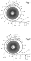
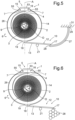
- THE figures 1 to 3 each show a schematic representation of a first embodiment of a hairspring 1, in particular for a timepiece regulating organ.
- the three figures show three different configurations of the hairspring 1.
- the spiral spring 1 extends substantially in a plane.
- the spiral spring 1 comprises a flexible ribbon 2 wound on itself in several turns, the ribbon 2 having a predefined stiffness.
- the hairspring includes means for adjusting its stiffness.
- the adjustment means are particularly operable when the hairspring is mounted in a regulating organ, in particular assembled on a plate of a watch movement.
- the flexible element 5 comprises two flexible parts 15, 16 each connecting the ribbon 2 to a fixed support 53.
- the two flexible parts 15, 16 are arranged, one with respect to the other, by axial symmetry along an axis A of the spiral spring 1. In other words, the two flexible parts 15, 16 are positioned so as to be symmetrical with respect to said axis A.
- the axis A passes substantially through the center O of the spiral spring, and on the other hand, the axis A passes, preferably, through the external end 4 of the ribbon 2.
- the two flexible parts 15, 16 are arranged at the periphery of the spiral spring, so that the two flexible parts 15, 16 are arranged at the same distance from the center 0 of the spiral spring 1.
- the two flexible parts 15, 16 are preferably arranged relative to each other in a "mirror" type position relative to the axis A.
- the two flexible parts 15, 16 are preferably substantially identical.
- the flexible parts 15, 16 each comprise a curved flexible blade 55, preferably forming a semicircle, and extending from the end of the fixed support 53.
- Each curved flexible blade 55 is further connected to the external end 4 of the ribbon 2 by a main flexible blade 7.
- the main flexible blades 7 are here arranged in the extension of one another.
- the curved blade 55 forms a semi-circular rounding, which is extended by the single flexible blade 7 at one end and by the fixed support 53 on the other hand.
- the end 56 of the support itself forms a rounding with a counter-curvature opposite that of the curved blade 55.
- the end 56 of the support 53 is semi-rigid so that it can partially deform.
- the fixed support 53 has the shape of a trapezoid open on the large side towards the external end 4 of the ribbon 2.
- the adjustment means of the spiral spring 1 further comprise pre-stressing means 6 for applying a variable force or torque to the flexible element 5.
- pre-stressing means 6 for applying a variable force or torque to the flexible element 5.
- the torque or force is continuously adjustable by the pre-stressing means 6.
- the torque or force is not restricted to point values.
- the stiffness of the flexible element 5 can be adjusted with great precision.
- the prestressing means 6 apply a substantially identical force or torque to each flexible part 15, 16, from a single force F applied to the third body 19, via the two levers 14, 26.
- the directions of the forces are preferably substantially symmetrical with respect to the axis A.
- the prestressing means 6 further comprise two levers 14, 26 each connecting a curved blade 55 to the same movable body 19, preferably rigid, arranged on the other side of the spiral spring 1 relative to the fixed support 53.
- the movable body 19 here has the shape of an arc of a circle.
- the spiral spring 1 further comprises actuating means 10 for actuating the pre-stressing means 6.
- the support body 12 is in direct contact with it.
- the support body 12 comprises a rod 13 forming a lever against the prestressing means 6.
- the rod 13 comprises two ends 17, 18, a first end 17 being mounted on the deformable element 11, and a second end 18 being mounted against the prestressing means 6.
- the actuating means 10 push the movable body 19 to modify the stiffness of the flexible element 5.
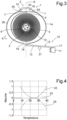
- the graph shows three superimposed curves 22, 23, 24 describing the effect of temperature on the operation of a regulating organ.
- the lower curve 24 describes the variation of the rate as a function of temperature, when there is no compensation according to the invention. Thus, when the temperature increases or decreases, the difference in rate compared to the rate at 23°C decreases.
- Such a curve can be produced with spiral springs mentioned in the patent EP1605182 .
- the upper curve 22 describes the variation of the step, which is obtained by the actuation means 10 according to the invention.
- the effect of the actuation means 10, represented on the upper curve 22, compensates for the effect of the temperature variation represented on the lower curve 24, so that the step remains substantially constant despite the temperature difference.
- a second embodiment of spiral spring 1 is shown in the Figure 5 , in which the spiral spring 1 is substantially identical to the first embodiment, except for the deformable element 27 of the adjustment means 10.
- the deformable element 27 comprises a bimetallic strip, or bimetallic strip, which deforms depending on the temperature.
- the bimetallic strip bends more or less.
- the second end 28 of the bimetallic strip pulls or pushes the first end 17 of the rod 12, which actuates the prestressing means 6.
- the deformable element 28 comprises a microstructure, or even a nanostructure, for example alveolar, which deforms depending on the temperature.
- a microstructure, or even a nanostructure is configured to deform, in a manner similar to the first embodiment.
- the rod 13 is moved in a manner similar to the first embodiment.
- the flexible blades described in the different embodiments of the spiral spring can be continuous flexible blades, as is generally the case in the figures, or blades with rigid sections and flexible necks connecting the sections.
- the invention also relates to a regulating member, not shown in the figures, in particular for a watch movement.
- the regulating member comprises, for example, an oscillating weight and a balance spring as described above.
- the oscillating weight is for example an annular balance.
- the oscillating weight is joined to the balance spring to be secured to the support.
Landscapes
- Physics & Mathematics (AREA)
- General Physics & Mathematics (AREA)
- Engineering & Computer Science (AREA)
- Metallurgy (AREA)
- Manufacturing & Machinery (AREA)
- Springs (AREA)
- Brushes (AREA)
Priority Applications (5)
| Application Number | Priority Date | Filing Date | Title |
|---|---|---|---|
| EP23219393.8A EP4575666A1 (de) | 2023-12-21 | 2023-12-21 | Spiralfeder für regulierorgan einer uhr mit temperaturabhängigen einstellmitteln |
| US18/926,557 US20250208573A1 (en) | 2023-12-21 | 2024-10-25 | Balance spring for a horological regulating member provided with temperature-dependent adjustment means |
| TW113141899A TWI915056B (zh) | 2023-12-21 | 2024-11-01 | 游絲及具有此游絲之鐘錶調節構件 |
| JP2024205133A JP2025100384A (ja) | 2023-12-21 | 2024-11-26 | 温度に依存する調節手段を備える、測時器調速部材のためのひげぜんまい |
| CN202411848553.2A CN120195954A (zh) | 2023-12-21 | 2024-12-16 | 设有温度相关调节装置的用于钟表调速机构的游丝 |
Applications Claiming Priority (1)
| Application Number | Priority Date | Filing Date | Title |
|---|---|---|---|
| EP23219393.8A EP4575666A1 (de) | 2023-12-21 | 2023-12-21 | Spiralfeder für regulierorgan einer uhr mit temperaturabhängigen einstellmitteln |
Publications (1)
| Publication Number | Publication Date |
|---|---|
| EP4575666A1 true EP4575666A1 (de) | 2025-06-25 |
Family
ID=89308068
Family Applications (1)
| Application Number | Title | Priority Date | Filing Date |
|---|---|---|---|
| EP23219393.8A Pending EP4575666A1 (de) | 2023-12-21 | 2023-12-21 | Spiralfeder für regulierorgan einer uhr mit temperaturabhängigen einstellmitteln |
Country Status (4)
| Country | Link |
|---|---|
| US (1) | US20250208573A1 (de) |
| EP (1) | EP4575666A1 (de) |
| JP (1) | JP2025100384A (de) |
| CN (1) | CN120195954A (de) |
Citations (8)
| Publication number | Priority date | Publication date | Assignee | Title |
|---|---|---|---|---|
| US38393A (en) * | 1863-05-05 | 1863-05-05 | Improvement in watches | |
| EP1422436A1 (de) | 2002-11-25 | 2004-05-26 | CSEM Centre Suisse d'Electronique et de Microtechnique SA | Spiraluhrwerkfeder und Verfahren zu deren Herstellung |
| EP1605182A1 (de) | 2004-06-08 | 2005-12-14 | CSEM Centre Suisse d'Electronique et de Microtechnique S.A. - Recherche et Développement | Unruh-Spiralfeder-Oszillator mit Temperaturkompensation |
| CH704687A1 (fr) * | 2011-03-23 | 2012-09-28 | Lvmh Swiss Mft Sa | Organe réglant pour pièce d'horlogerie. |
| EP2876504A1 (de) | 2013-11-20 | 2015-05-27 | ETA SA Manufacture Horlogère Suisse | Schraubenloser Spiralklötzchen-Träger für Uhr |
| WO2016192957A1 (fr) | 2015-06-03 | 2016-12-08 | Eta Sa Manufacture Horlogère Suisse | Résonateur à réglage fin par raquetterie |
| EP4009115A1 (de) | 2020-12-02 | 2022-06-08 | Omega SA | Spiralfeder für resonatormechanismus eines uhrwerks, der mit mitteln zum ausgleichen der starrheit ausgestattet ist |
| EP4310600A1 (de) * | 2022-07-21 | 2024-01-24 | The Swatch Group Research and Development Ltd | Regulierorgan für uhrwerk mit spiralfeder, das mit temperaturausgleichsmitteln ausgestattet ist |
-
2023
- 2023-12-21 EP EP23219393.8A patent/EP4575666A1/de active Pending
-
2024
- 2024-10-25 US US18/926,557 patent/US20250208573A1/en active Pending
- 2024-11-26 JP JP2024205133A patent/JP2025100384A/ja active Pending
- 2024-12-16 CN CN202411848553.2A patent/CN120195954A/zh active Pending
Patent Citations (8)
| Publication number | Priority date | Publication date | Assignee | Title |
|---|---|---|---|---|
| US38393A (en) * | 1863-05-05 | 1863-05-05 | Improvement in watches | |
| EP1422436A1 (de) | 2002-11-25 | 2004-05-26 | CSEM Centre Suisse d'Electronique et de Microtechnique SA | Spiraluhrwerkfeder und Verfahren zu deren Herstellung |
| EP1605182A1 (de) | 2004-06-08 | 2005-12-14 | CSEM Centre Suisse d'Electronique et de Microtechnique S.A. - Recherche et Développement | Unruh-Spiralfeder-Oszillator mit Temperaturkompensation |
| CH704687A1 (fr) * | 2011-03-23 | 2012-09-28 | Lvmh Swiss Mft Sa | Organe réglant pour pièce d'horlogerie. |
| EP2876504A1 (de) | 2013-11-20 | 2015-05-27 | ETA SA Manufacture Horlogère Suisse | Schraubenloser Spiralklötzchen-Träger für Uhr |
| WO2016192957A1 (fr) | 2015-06-03 | 2016-12-08 | Eta Sa Manufacture Horlogère Suisse | Résonateur à réglage fin par raquetterie |
| EP4009115A1 (de) | 2020-12-02 | 2022-06-08 | Omega SA | Spiralfeder für resonatormechanismus eines uhrwerks, der mit mitteln zum ausgleichen der starrheit ausgestattet ist |
| EP4310600A1 (de) * | 2022-07-21 | 2024-01-24 | The Swatch Group Research and Development Ltd | Regulierorgan für uhrwerk mit spiralfeder, das mit temperaturausgleichsmitteln ausgestattet ist |
Also Published As
| Publication number | Publication date |
|---|---|
| US20250208573A1 (en) | 2025-06-26 |
| TW202526529A (zh) | 2025-07-01 |
| JP2025100384A (ja) | 2025-07-03 |
| CN120195954A (zh) | 2025-06-24 |
Similar Documents
| Publication | Publication Date | Title |
|---|---|---|
| EP4009115A1 (de) | Spiralfeder für resonatormechanismus eines uhrwerks, der mit mitteln zum ausgleichen der starrheit ausgestattet ist | |
| EP4187326A1 (de) | Spiralfeder für resonatormechanismus eines uhrwerks, der mit mitteln zum ausgleichen der starrheit ausgestattet ist | |
| EP4286962B1 (de) | Regulierorgan für uhr, das eine rückervorrichtung umfasst, die mit verriegelungsmitteln ausgestattet ist | |
| EP4286960B1 (de) | Regulierorgan für uhr, das mit einer rückervorrichtung ausgestattet ist | |
| CH718113A2 (fr) | Ressort-spiral pour mécanisme résonateur d'horlogerie muni de moyens d'ajustement de la rigidité. | |
| EP2908183B1 (de) | Spiralfeder einer Uhr | |
| EP4575666A1 (de) | Spiralfeder für regulierorgan einer uhr mit temperaturabhängigen einstellmitteln | |
| CH719183A2 (fr) | Ressort-spiral pour mécanisme résonateur d'horlogerie muni de moyens d'ajustement de la raideur. | |
| CH721442A2 (fr) | Ressort-spiral pour organe réglant d'horlogerie muni de moyens d'ajustement dépendants de la température | |
| EP4310602B1 (de) | Regulierorgan für uhrwerk mit spiralfeder, das mit mitteln zum ausgleich der schwerkraft ausgestattet ist | |
| EP4310600B1 (de) | Regulierorgan für uhrwerk mit spiralfeder, das mit temperaturausgleichsmitteln ausgestattet ist | |
| EP4546058A1 (de) | Spiralfeder für resonatormechanismus einer uhr mit symmetrischen steifigkeitseinstellmitteln | |
| EP4575667A1 (de) | Halter für uhreinstellorgan mit mitteln zur gangeinstellung und/oder isochronismuseinstellung | |
| EP4557015A1 (de) | Regulierorgan für uhr, das ein betätigungssystem mit einem exzenter umfasst | |
| CH721423A2 (fr) | Porte-piton pour organe réglant d'horlogerie muni de moyens d'ajustement de la marche et/ou de l'isochronisme | |
| EP4134754A1 (de) | Trägheitsmasse, die mit einem flexiblen trägheitselement ausgestattet ist, insbesondere für uhrwerke | |
| CH721231A2 (fr) | Ressort-spiral pour mécanisme résonateur d'horlogerie muni de moyens d'ajustement symétriques de la raideur | |
| CH721296A2 (fr) | Organe réglant d'horlogerie comprenant un système d'actionnement muni d'un excentrique | |
| EP4498176A1 (de) | Regulierungsorgan für uhren, das mit einem linearem betätigungssystem augerustet ist | |
| EP4530756A1 (de) | Uhreinstellorgan mit verbessertem rückersystem | |
| EP4498174A1 (de) | Regulierorgan für uhren, das ein betätigungssystem mit einer steuerwippe umfasst | |
| EP4498175A1 (de) | Uhreinstellorgan mit hakenbetätigungssystem | |
| CH720982A2 (fr) | Organe réglant d'horlogerie comprenant un système d'actionnement muni d'une bascule de commande | |
| CH720980A2 (fr) | Organe réglant d'horlogerie muni d'un système d'actionnement linéaire | |
| CH720973A2 (fr) | Organe réglant d'horlogerie muni d'un système d'actionnement à crochet |
Legal Events
| Date | Code | Title | Description |
|---|---|---|---|
| PUAI | Public reference made under article 153(3) epc to a published international application that has entered the european phase |
Free format text: ORIGINAL CODE: 0009012 |
|
| STAA | Information on the status of an ep patent application or granted ep patent |
Free format text: STATUS: THE APPLICATION HAS BEEN PUBLISHED |
|
| AK | Designated contracting states |
Kind code of ref document: A1 Designated state(s): AL AT BE BG CH CY CZ DE DK EE ES FI FR GB GR HR HU IE IS IT LI LT LU LV MC ME MK MT NL NO PL PT RO RS SE SI SK SM TR |
|
| STAA | Information on the status of an ep patent application or granted ep patent |
Free format text: STATUS: REQUEST FOR EXAMINATION WAS MADE |
|
| 17P | Request for examination filed |
Effective date: 20251219 |