EP4575676A1 - Uhrwerk, das ein starres bewegliches element umfasst, das mit einem elastischen element gekoppelt ist, und verfahren zum verbinden dieser elemente - Google Patents
Uhrwerk, das ein starres bewegliches element umfasst, das mit einem elastischen element gekoppelt ist, und verfahren zum verbinden dieser elemente Download PDFInfo
- Publication number
- EP4575676A1 EP4575676A1 EP24207292.4A EP24207292A EP4575676A1 EP 4575676 A1 EP4575676 A1 EP 4575676A1 EP 24207292 A EP24207292 A EP 24207292A EP 4575676 A1 EP4575676 A1 EP 4575676A1
- Authority
- EP
- European Patent Office
- Prior art keywords
- coupling member
- rotation
- housing
- coupling
- spring
- Prior art date
- Legal status (The legal status is an assumption and is not a legal conclusion. Google has not performed a legal analysis and makes no representation as to the accuracy of the status listed.)
- Pending
Links
Images


Classifications
-
- G—PHYSICS
- G04—HOROLOGY
- G04B—MECHANICALLY-DRIVEN CLOCKS OR WATCHES; MECHANICAL PARTS OF CLOCKS OR WATCHES IN GENERAL; TIME PIECES USING THE POSITION OF THE SUN, MOON OR STARS
- G04B17/00—Mechanisms for stabilising frequency
- G04B17/32—Component parts or constructional details, e.g. collet, stud, virole or piton
-
- G—PHYSICS
- G04—HOROLOGY
- G04B—MECHANICALLY-DRIVEN CLOCKS OR WATCHES; MECHANICAL PARTS OF CLOCKS OR WATCHES IN GENERAL; TIME PIECES USING THE POSITION OF THE SUN, MOON OR STARS
- G04B11/00—Click devices; Stop clicks; Clutches
- G04B11/006—Clutch mechanism between two rotating members with transfer of movement in only one direction (free running devices)
- G04B11/008—Clutch mechanism between two rotating members with transfer of movement in only one direction (free running devices) with friction members, e.g. click springs or jumper
-
- G—PHYSICS
- G04—HOROLOGY
- G04B—MECHANICALLY-DRIVEN CLOCKS OR WATCHES; MECHANICAL PARTS OF CLOCKS OR WATCHES IN GENERAL; TIME PIECES USING THE POSITION OF THE SUN, MOON OR STARS
- G04B17/00—Mechanisms for stabilising frequency
- G04B17/04—Oscillators acting by spring tension
- G04B17/06—Oscillators with hairsprings, e.g. balance
- G04B17/066—Manufacture of the spiral spring
-
- G—PHYSICS
- G04—HOROLOGY
- G04B—MECHANICALLY-DRIVEN CLOCKS OR WATCHES; MECHANICAL PARTS OF CLOCKS OR WATCHES IN GENERAL; TIME PIECES USING THE POSITION OF THE SUN, MOON OR STARS
- G04B19/00—Indicating the time by visual means
- G04B19/24—Clocks or watches with date or week-day indicators, i.e. calendar clocks or watches; Clockwork calendars
- G04B19/243—Clocks or watches with date or week-day indicators, i.e. calendar clocks or watches; Clockwork calendars characterised by the shape of the date indicator
- G04B19/247—Clocks or watches with date or week-day indicators, i.e. calendar clocks or watches; Clockwork calendars characterised by the shape of the date indicator disc-shaped
- G04B19/253—Driving or releasing mechanisms
- G04B19/25333—Driving or releasing mechanisms wherein the date indicators are driven or released mechanically by a clockwork movement
- G04B19/25353—Driving or releasing mechanisms wherein the date indicators are driven or released mechanically by a clockwork movement driven or released stepwise by the clockwork movement
-
- G—PHYSICS
- G04—HOROLOGY
- G04B—MECHANICALLY-DRIVEN CLOCKS OR WATCHES; MECHANICAL PARTS OF CLOCKS OR WATCHES IN GENERAL; TIME PIECES USING THE POSITION OF THE SUN, MOON OR STARS
- G04B19/00—Indicating the time by visual means
- G04B19/24—Clocks or watches with date or week-day indicators, i.e. calendar clocks or watches; Clockwork calendars
- G04B19/243—Clocks or watches with date or week-day indicators, i.e. calendar clocks or watches; Clockwork calendars characterised by the shape of the date indicator
- G04B19/247—Clocks or watches with date or week-day indicators, i.e. calendar clocks or watches; Clockwork calendars characterised by the shape of the date indicator disc-shaped
- G04B19/253—Driving or releasing mechanisms
- G04B19/25333—Driving or releasing mechanisms wherein the date indicators are driven or released mechanically by a clockwork movement
- G04B19/25373—Driving or releasing mechanisms wherein the date indicators are driven or released mechanically by a clockwork movement driven or released stepwise by an energy source which is released at determined moments by the clockwork movement
Definitions
- the present invention relates to a watch movement in which is incorporated a device comprising a coupled rigid element and an elastic element.
- the device is a mechanism for driving an indicator by jumping.
- the rigid element comprises a drive finger for driving the jumping indicator.
- the elastic element is a spring comprising a coil between its first end and its second end, the first end being rotationally fixed to a wheel board and the second end carrying a coupling member, which is inserted at least partially into a housing provided by the rigid element.
- the invention also relates to a method for coupling a rigid element with an elastic element during assembly of a mechanical device or mounting of the latter in a watch movement, in particular a drive mechanism for a jumping indicator.
- the document EP 3828644 describes a drive mechanism for a semi-instantaneous jump indicator comprising a drum finger and a spring arranged in this drum and coupled to it, the first end of the spring being integral in rotation with a wheel board, driving this first end, and the second end carrying a coupling member partially inserted in its own housing, that is to say a housing which is arranged for this coupling member and intended solely for this coupling member, which the drum finger has, in a mobile manner with a significant clearance.
- the spring coupling member is arranged in a shallow housing from which this member can easily emerge.
- the two lateral surfaces of the housing are parallel in a radial direction passing through the middle of the housing, and the coupling member has two radial flanks.
- the angular width of the coupling member is designed to be significantly smaller than that of the housing in order to allow this member to easily penetrate into the housing. Thus, a relatively small impact can easily result in the coupling member coming out of its housing.
- the coupling member comes out of the housing when the spring is loaded against a tooth of the date ring, either it then slides along the inner side surface and the date jump will not take place at least until the drive wheel has made one revolution and the coupling member enters its housing again (the most favorable case which however results in the loss of a correct display of the date, which has missed a daily jump), or the friction force is sufficient for the spring to be loaded again by expansion, further increasing the friction force, until its coil touches the side wall and a date jump takes place at an undetermined time. In the latter case, after the date jump, the spring will relax, driving the drum and presumably the coupling member will undergo a certain abrupt angular displacement along the side wall.
- the mechanism disclosed in the document EP 3828644 presents a significant problem in connection with the assembly of this mechanism.
- the cylindrical inner space of the drum finger is circular with the housing machined on the periphery of this cylindrical and circular inner space. Since the coupling member must be inserted partly into the peripheral housing and remain in this housing during normal operation, this spring has a radial distance from the center of the rigid ring, to which the first end of the spring is fixed, to the outer lateral surface of the coupling member, when the spring is unstressed (i.e. relaxed / at rest / in its neutral position), which is greater than the radius of said circular cylindrical inner space.
- the spring poses a major problem for the assembly of the mechanism, which is of small dimensions (the spring generally has a diameter of less than 4 mm). Indeed, if we consider a possible assembly method in which the spring is in a relaxed state, the drum finger and the spring must be arranged, when they are brought onto the wheel board, with a relatively precise relative angular positioning in which the coupling member is substantially aligned with the housing of the drum finger and introduced axially into this housing.
- the relative angular positioning mentioned above is not obvious because the spring is very small. In addition, this spring is not visible when the drum finger is placed on the wheel board to then allow their assembly with a hub which has a shaft inserted into the oblong hole of the drum finger, the hole of the rigid ring and the central hole of the wheel board from the side of the drum finger ( Fig. 5 of the document). Specific technical means or delicate handling by the watchmaker must be provided to allow such relative angular positioning.
- the coupling member can easily come out of the housing as long as the shaft is not inserted into the hole in the rigid ring, this hole then no longer being axially aligned with the oblong hole in the drum finger, which makes assembly difficult because the coupling member must therefore be reinserted into the housing. When leaving the housing, it is very likely that the coupling member will undergo an angular displacement relative to the housing so that its reintroduction becomes random and not certain.
- the technological background shows a need in the watchmaking field for a device, formed by a rigid element and an elastic element coupled by means of a coupling member which is carried by the elastic element and inserted at least partially in a specific housing that the rigid element has, which is configured so as to simplify its assembly or mounting in a watch movement in relation to the coupling of the rigid element with the elastic element, and for a method of coupling the rigid element with the elastic element, during the assembly or mounting of such a device, which is easy to implement.
- the invention relates to a watch movement comprising a device formed by a support, a rigid element which is movable and an elastic element which is coupled to this rigid element, the elastic element comprising a first end which is integral in movement, at least in a first direction, of the support and a second end carrying a coupling member inserted at least partially in a proper housing that the rigid element has.
- the support, the rigid element and the elastic element are arranged in such a way that, when forming the device, they can be pre-mounted in the watch movement or pre-assembled in an intermediate state in which: - the first end of the elastic element is integral in movement, in the first direction, with the support; - the rigid element and the support with the elastic element have an initial relative position, among a range of possible relative positions, for which the elastic element is relaxed; and - the coupling member is located outside its own housing.
- the rigid element comprises a stress ramp provided for the elastic element and located near said own housing, the stress ramp being arranged so that, at least during assembly of the device or mounting of the device in the watch movement from said intermediate state, the coupling member can come to bear against the stress ramp, by a guided relative movement between the rigid element and the support in the first direction, from said initial relative position and then follow this stress ramp by approaching the own housing while the relative movement is continued with at least one non-zero component in the first direction, the stress ramp being arranged so that, during this continuation of the relative movement, the coupling member undergoes a displacement relative to the support, at least one non-zero component of which is in a second direction not parallel to the first direction, and the elastic element is then stressed.
- the coupling member is configured to be able, after having followed the stress ramp while approaching the housing itself, to penetrate at least partially into this housing itself, while the elastic element undergoes at least a partial relaxation, and finally to occupy a functional coupling position in which it remains during any normal operation of the watch movement.
- the device is configured so that the elastic element is substantially relaxed, i.e. not stressed, once the coupling member is in the functional coupling position following assembly of the device or mounting of this device in the watch movement.
- said first direction is an angular direction relative to an axis of rotation, defining a rotation around this axis
- said second direction is a radial direction, relative to said axis of rotation, which passes through a geometric center of the coupling member.
- said range of possible relative positions in said intermediate state extends over at least 20°.
- the range of possible relative positions in the intermediate state extends over at least 45°, preferably over at least 60°.
- the device is a mechanism for driving a jumping indicator
- the elastic element being a spring comprising a coil between its first end and its second end
- said support being a wheel board which is mounted to rotate around said axis of rotation and which drives the first end of the spring
- the rigid element comprising a drive finger arranged to drive the jumping indicator in a given drive direction.
- the stress ramp is arranged so that, when the coupling member follows this stress ramp while approaching its own housing, the coupling member undergoes a radial displacement towards the axis of rotation and the coil of the spring is then stressed.
- the spring, the coupling member and the stress ramp are arranged so that, during the coupling step, the coupling member slides, after having followed the stress ramp, on a terminal zone of this stress ramp, during said relative movement, before the coupling member reaches said functional coupling position in its own housing.
- the stress ramp, the spring and the coupling member are arranged in such a way that, when the coupling member follows the stress ramp while approaching its own housing, the coupling member undergoes a rotation on itself which promotes or allows a subsequent penetration of this coupling member into its own housing, so that the coupling member can reach the functional coupling position.
- the first direction is an angular direction relative to an axis of rotation, defining a rotation around this axis
- the second direction is a radial direction, relative to said axis of rotation, which passes through a geometric center of the coupling member, which thus undergoes a radial displacement when it follows the stress ramp while approaching its own housing.
- a guided relative movement between the support and the rigid element, up to contact of the coupling member with the stress ramp, other than a rotation is provided.
- a first direction other than an angular direction is provided, in particular a linear direction. More complex guided relative movements may possibly be implemented.
- the continuation of the relative movement, in a second phase of the relative movement, to allow the coupling member to climb the stress ramp may be a more complex relative movement than a linear movement or a rotation occurring, in the first phase of the relative movement, before the coupling member comes to bear against the stress ramp, in particular when the rigid element undergoes a displacement in reaction to a pressure exerted by the coupling member on the stress ramp.
- the method comprises, before the coupling step, an initial step in which a hub comprising a shaft and a head, the wheel board, the spring provided at its first end with a central rigid part and the plate, respectively the plate with the rigid element mounted on this plate are brought and positioned so that the wheel board, the spring and the plate, respectively the rigid element are in a relative position angularly corresponding to a said possible relative position with the spring located between the wheel board and the pad and the head located on a side opposite the spring relative to the pad; and such that the shaft, a first hole in the pad, a second hole in the wheel board and a third hole defined by the central rigid part are aligned on said axis of rotation, the second hole having a diameter smaller than the first hole and the head being at least partially superimposed on the pad; and then an assembly step including said securing step and in which the shaft is force-fitted into the second hole in the wheel board
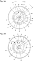
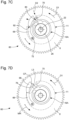
- a first embodiment of a watch movement 2 which incorporates a device for driving a jumping indicator, and a first mode of implementing a method for coupling a rigid element with an elastic element during assembly or mounting of the device.
- the device 6 forms a mechanism for driving a jumping indicator 4, in particular by semi-instantaneous jumping.
- This device 6 comprises a support formed by a wheel board 8, a rigid element forming a drum finger 10 and arranged above the wheel board, and an elastic element formed by a spring 16.
- This spring comprises a first end 17, a coil 18 and a second end 19.
- the wheel board 8 has an axis of rotation 22.
- the drum finger 10 defines a drive finger 12 for the indicator 4, which here forms a date ring.
- This drum finger has a drive flank 14 intended to come into contact with a tooth of a set of teeth 5 of the indicator to drive this indicator by jumping.
- the drum finger is rotatable relative to the wheel board 8 and guided in rotation about the axis of rotation 22 by a shaft 28, which has a hub 26, passing through an oblong hole 34 that the drum finger has.
- the first end 17 of the spring 16 is connected to a central rigid part 24 which is integral in rotation with the wheel board 8.
- the spring and the central part form a single piece.
- the drum finger 10 is formed by a plate 30, which extends above the spring 16 and in which the oblong hole 34 is machined, and an axial wall 32 arranged at the edge of this plate and which lowers towards the wheel board 8, on which it can rest in a variant.
- the drum finger thus defines an interior space 9 in which the spring is arranged.
- the wheel board 8 and the central rigid portion 24 are driven onto the shaft 28 of the hub 26, which further comprises a head 27 which extends partially above the plate 30 so as to maintain the drum finger 10 in axial position.
- the axial wall 32 has, at the level of the drive finger, a housing 36 which has a lateral opening on the side of the spring 16, namely on the side of the axis of rotation 22 of the device 6.
- the second end 19 of the spring is extended by a member 20 for coupling to the rigid element 10 (namely here the drum finger), this coupling member 20 being configured so as to be able to penetrate at least partially into the housing 36, which is a proper housing for the coupling member, through the lateral opening and allow the spring to then be able to apply a driving force torque to the rigid element 10.
- the coupling member 20 is rigid.
- the housing 36 has a lateral surface 54 oriented obliquely in the direction of rotation 56 of the wheel board 8, the direction intended for driving the indicator, relative to a radial direction passing through the middle of the lateral surface
- the coupling member 20 has a lateral flank 52, opposite the lateral surface, which is also inclined obliquely in the same direction as the lateral surface and which presses at least partially against the lateral surface during each loading of the spring 16 for driving the jumping indicator by the mechanism 6.
- the coupling member 20 has a nose 42, defining the lateral flank 52, which is configured to fit into a complementary shape of the housing 36 having substantially the same profile.
- This particular characteristic makes it possible to ensure precise maintenance of the coupling member in a given driving position inside the housing as soon as the spring is put under tension during loading, the lateral surface exerting a reaction force on the nose 42 of the coupling member with a component directed towards the outside and therefore towards the bottom of the housing itself 36.
- the nose 42 remains in a given driving position for which the radius of application of the driving force of the spring on the drum finger 10 remains identical during loading of the spring and substantially maximum. It results from this characteristic that the transmitted force torque is thus maximum for a determined driving force of the spring during its loading.
- the coupling member 20 has a rear heel provided to block a rotation of the coupling member on itself, once inserted into its own housing 36, in the direction of rotation 56 of the wheel board (direction of rotation provided for driving the indicator).
- This rear heel is extended by a contact surface 46 which comes to bear against an angular stop 48 at the end of loading of the spring 16, to then generate a jump of the indicator.
- the angular stop 48 is located between the first end 17 of the spring and the central rigid ring 24, in the angular extension of the coil 18 of the spring, and is defined by the single and same part forming the rigid ring and the spring.
- the housing has a minimum dimension on the side of its opening which is slightly less than a maximum dimension of the coupling member perpendicular to the radial direction, relative to the central axis of the rigid ring merged with the axis of rotation 22, with the spring in an angularly relaxed state.
- the coupling member and its own housing are arranged in such a way that the coupling member cannot come out of its own housing by at least one translation relative to the rigid part, that is to say without undergoing at least one rotation on itself (rotation around its geometric center along an axis parallel to the axis of rotation 22).
- the coupling member To enter the housing through the side opening, the coupling member must therefore perform a slight rotation on itself, around its geometric center 21.
- this coupling member 20 remains normally coupled to the drum finger 10 at all times regardless of the state of the device 6, that is to say in a state of the spring not angularly constrained in the periods without interaction between the teeth 5 of the indicator 4 and the drive finger 12, in a state where the spring works in contraction during a loading thereof before a jump of the indicator, during a jump of this indicator, and also when the spring is slightly constrained in expansion in particular when the wheel plate 8 is driven in rotation in a direction of rotation opposite to the direction intended to drive the indicator 4, in order to carry out a correction of the time in a counterclockwise direction.
- the coupling member 20 remains coupled to the drum finger as intended, that is to say in place in the proper housing 36, and thus secured to the drum finger.
- the coupling member occupies a functional coupling position in which it remains during any normal operation of the watch movement. It will be noted that in normal operation, no shocks are expected, generating strong accelerations, and that the watch movement is generally subjected to strong accelerations.
- the method of coupling a rigid element with an elastic element, during an assembly or mounting of a device intended to form a watch movement concerns an element elastic, in particular a spring which may have various shapes, comprising a first end, intended to be assembled with a support, in particular a wheel board, which the device or the watch movement comprises, and a second end carrying a coupling member, intended to be assembled with the rigid element to couple the rigid element with the elastic element.
- the rigid element in particular a rocker or a drum finger which is arranged to move relative to the support and on which it is intended to exert a restoring force, has its own housing for the coupling member and a stress ramp located near its own housing and intended to guide the elastic element by momentarily stressing it during the coupling process.
- said first direction is an angular direction D1 relative to the axis of rotation 22, defining a rotation about this axis
- said second direction is a radial direction D2, relative to the axis of rotation 22, which passes through a geometric center 21 of the coupling member, which thus undergoes a radial displacement when it follows the stress ramp 40 while approaching its own housing 36.
- the device is a mechanism 6 for driving a jumping indicator 4, the elastic element being a spring 16 comprising a coil 18 between its first end 17 and its second end 19.
- the support is a wheel board 8 which is driving the first end of the spring 16 and defines the axis of rotation 22.
- the rigid element 10 comprises a driving finger 12 for driving the jumping indicator in a given driving direction.
- the spring 16 is forced into contraction during the relative movement MR intended to effect the coupling of the spring 16 with the rigid element 10 via the proper housing 36 defined by this rigid element and the coupling member 20 carried by the second end 19 of the spring, this coupling member preferably being integral with the spring and thus forming a single part with this spring.
- the central rigid ring 24 is advantageously also fixed to the first end 17 of the spring so as to form a single part with this spring.
- the spring, the coupling member and the central rigid ring are formed by a single and same part.
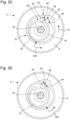
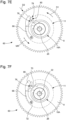
- the spring 16 and the rigid ring 24 are arranged so as to present, when the spring is relaxed, a free space 38 into which the coupling member 20 can penetrate when the spring is forced into contraction. This is important for the coupling process, in the variant shown, and also for the operation of the mechanism 6 when driving an indicator 4, in particular a date ring.
- the spring 16 is charged by a contraction of its coil 18 until the contact surface 46 of the coupling member comes to bear against the angular stop 48 ( Figure 4B ). Then, shortly after this event, the date ring jump is triggered. In another variant, the jump can be triggered before the contact surface 46 comes to bear against the angular stop 48, the latter then forming a safety stop for the spring, so that it cannot be damaged.
- the stress ramp 40 is arranged upstream of the housing 36 relative to the direction of rotation 56 of the wheel board 8 when the jumping indicator 4 is driven by the mechanism 6 in the given driving direction.
- the particular shape of the coupling member 20, the arrangement of the spring 16 and the configuration of the stress ramp 40 have the consequence that, during the coupling step, the coupling member slides, after having followed the stress ramp, on an end zone of this stress ramp, during said guided relative movement MR, before the at least partial penetration of the coupling member 20 into the proper housing 36 and the occupation of the functional coupling position by this coupling member.
- the stress ramp 40, the spring 16 and the coupling member 20 are arranged in such a way that, when the coupling member follows the stress ramp while approaching the own housing 36, the coupling member undergoes a rotation on itself, that is to say it rotates around its geometric center 21, which promotes or, in a preferred variant, which allows a subsequent penetration of this coupling member into the own housing, so that the coupling member can reach the functional coupling position.
- this variant is advantageous, because it makes it possible to design complementary shapes for the coupling member and the own housing in such a way that the coupling member no longer comes out of the own housing in practice in the event of an impact.
- the rotation of the coupling member on itself is obtained, when assembling the spring to the rigid element defining its own housing, by the relative rotational movement between the rigid element and the support (the drum finger and the wheel board) thanks to the constraint ramp 40 which constrains the spring 16 by a displacement, having a main component which is radial, of the coupling member 20 towards the rotation axis 22, generating the rotation of this member on itself in a sufficient manner to allow an orientation allowing its introduction into the own housing 36. This is remarkable.
- the range of possible relative positions P1( ⁇ ) of the spring 16 in a relaxed/unstressed state, placed in the interior space 9 of the drum finger 10 during assembly or mounting of the mechanism 6, in said intermediate state extends over approximately 75°.
- This value corresponds to a preferred variant, in which the range of possible relative positions extends over at least 60°.
- the range of possible relative positions in the intermediate state extends over at least 20°, whereas in an advantageous variant, this range extends over at least 45°.
- the spring is then constrained by the constraint ramp during the planned guided relative movement MR and the introduction of the coupling member into its own housing then takes place with at least partial relaxation of the spring, so that this member remains in its own housing in the absence of external constraints.
- the end portion of the constraint ramp defines an edge of the coupling member's own housing, the opposite edge of this own housing being advantageously located approximately at the same radial distance from the axis of rotation 22.
- the rigid element 10 is formed by a plate 30 or is mounted to be movable in rotation on a plate (case related to the second embodiment which will be described later).
- the coupling method comprises, before the coupling step, an initial step in which the wheel board 8, the spring 16 and the plate 30, in particular the drum finger 10 which is formed in part by this plate 30 in the variant shown, are brought and positioned in said initial relative position with the spring located between the wheel board and the plate; and then it comprises an assembly step including said securing step and in which the hub 26, comprising a shaft 28 and a head 27, is brought to the side of the plate and the shaft is introduced into a first hole 34 (the oblong hole in the variant shown) that this plate has, into the rigid ring 24 to which the first end 17 of the spring is fixed and finally into a second hole that the wheel board 8 has, the second hole being sized so that the shaft 28 is force-fitted into this second hole while the first hole 34 is sized so that the plate 30, and therefore
- the central rigid ring 24 has a third hole which is sized so that the shaft is also force-fitted into this third hole to secure the first end of the spring to the wheel board.
- the rigid ring has an internal projecting part which is inserted into a corresponding cavity that the hub shaft comprises.
- the initial step of the particular variant described above is different in that the hub is first brought in, placed in a position, and then the drum finger is brought in by introducing the hub shaft into the oblong hole of this drum finger, then the spring is brought in with its rigid ring and the coupling member and this assembly is placed so that the hole of the rigid ring is positioned with an end part of the shaft of smaller diameter passing through it, this rigid ring being thus temporarily held above the interior space 9 of the drum finger. Then, the wheel board is brought in and positioned with the end part of the shaft also introduced into its central hole or aligned with this central hole. Finally, the rigid ring and the wheel board are forced onto the shaft while ensuring that the drum finger is left free to rotate. The device according to the invention is thus in said intermediate state.
- the present invention relates to the advantageous coupling method between an elastic element and a rigid element of a watch movement device, method described above, and also a watch movement comprising such a device and arranged so as to allow the implementation of the coupling method according to the invention.
- a general embodiment of a watch movement comprises a device formed by a support, a rigid element which is movable and an elastic element which is coupled to this rigid element, the elastic element comprising a first end which is integral in movement, at least in a first direction, with the support and a second end carrying a coupling member inserted at least partially in a specific housing that the rigid element has.
- the support, the rigid element and the elastic element are arranged in such a way that, when forming the device, they can be pre-mounted in the watch movement or pre-assembled in an intermediate state in which: - the first end of the elastic element is integral in movement, in the first direction, with the support; - the rigid element and the support with the elastic element have an initial relative position, among a range of possible relative positions, for which the elastic element is relaxed; and - the coupling member is located outside its own housing.
- the rigid element comprises a stress ramp provided for the elastic element and located close to the housing itself, the stress ramp being arranged so that, at least during assembly of the device or mounting of the device in the watch movement from said intermediate state, the coupling member can come to bear against the stress ramp, by a guided relative movement between the rigid element and the support in the first direction, from said initial relative position and then follow this stress ramp by approaching the housing itself while the relative movement is continued with at least one non-zero component in the first direction, the stress ramp being arranged so that, during this continuation of the relative movement, the coupling member undergoes a displacement relative to the support, of which at least a non-zero component is in a second direction not parallel to the first direction, and the elastic element is then stressed.
- the coupling member is configured to be able, after having followed the stress ramp while approaching the own housing, to penetrate at least partially into this own housing, while the elastic element undergoes at least partial relaxation, and finally to occupy a functional coupling position in which it remains during any normal operation of the watch movement.
- the spring 16, the coupling member 20 and the stress ramp 40 are arranged in such a way that the coupling member can, after having followed the stress ramp while approaching its own housing, slide on an end zone of the stress ramp, while said relative movement is continued, before the coupling member reaches said functional coupling position in said own housing.
- the first direction is an angular direction, relative to an axis of rotation, defining a rotation around this axis
- the second direction is a radial direction, relative to said axis of rotation, which passes through a geometric center of the coupling member.
- said range of possible relative positions in said intermediate state extends over at least 20°. In an advantageous variant, said range of possible relative positions in said intermediate state extends over at least 45°, preferably over at least 60°.
- the device is a mechanism 6 for driving a jumping indicator 4, the elastic element being a spring 16 comprising a coil 18 between its first end 17 and its second end 19, said support being a wheel board 8 which drives the first end of the spring and which defines said axis of rotation (the axis of rotation 22), the rigid element (drum finger or rocker) comprising a finger drive 12 arranged to be able to periodically carry out the driving of the jumping indicator in a given driving direction 50.
- the elastic element being a spring 16 comprising a coil 18 between its first end 17 and its second end 19, said support being a wheel board 8 which drives the first end of the spring and which defines said axis of rotation (the axis of rotation 22), the rigid element (drum finger or rocker) comprising a finger drive 12 arranged to be able to periodically carry out the driving of the jumping indicator in a given driving direction 50.
- the stress ramp 40, the spring 16 and the coupling member 20 are arranged in such a way that, when the coupling member follows the stress ramp while approaching the housing 36 itself, the coupling member can undergo a rotation on itself which promotes or allows a subsequent penetration of this coupling member into said housing, so that the coupling member can finally reach said functional coupling position.
- the rigid element 10 is formed by a plate 30 which extends above the spring, on the side opposite the wheel board 8, and by an axial wall 32 arranged at the edge of the plate and which lowers towards the wheel board, at least a part of the axial wall and a part of the plate which is superimposed on it together forming the drive finger 12.
- the plate has an oblong hole and is guided in rotation around the axis of rotation 22, relative to the wheel board, by a shaft 28 fixed to this wheel board and passing through the oblong hole.
- the axial wall 32 defines the housing 36, which has a lateral opening on the spring side (i.e.
- the coupling member 20 being configured so as to be able to penetrate at least partially into the own housing 36 through the lateral opening, to finally reach said functional coupling position in which it remains during any normal operation of the watch movement, and to then allow the spring 16 to apply a driving force torque to the rigid element 10 and thus to the driving finger 12 to carry out the driving of the jumping indicator 4.
- the coupling member has, in a general plane of the spring, a first shape and the housing presents in this general plan a second shape with a dimension of said lateral opening which does not allow the coupling member to come out of its own housing only by at least one translation.
- the constraint ramp 40 is arranged upstream of the housing 36 relative to a direction of rotation 56 of the wheel plate 8 when the jumping indicator 4 is driven by the mechanism 6 in the given driving direction 50, so that said relative movement between the rigid element 10 and the wheel plate in the angular direction D1 is carried out for the wheel plate in said direction of rotation thereof.
- the mechanism 6 is arranged in such a way that, if the coupling member 20 possibly comes out of its own housing 36 during an impact or a certain strong acceleration undergone by the watch movement 2, this coupling member 20 can only occupy a pre-coupling position upstream of its own housing 36 relative to the direction of rotation 56 of the wheel plate 8 when the jumping indicator 4 is driven by the mechanism in said given driving direction 56.
- the mechanism is arranged in such a way that the coupling member can return to said functional coupling position when the wheel plate 8 is driven in rotation by the watch movement, in said direction of rotation 56 of this wheel plate, while the driving finger is bearing against a tooth that the jumping indicator comprises.
- This preferred variant is remarkable because, in the possible case of a specific impact which would cause the coupling member 20 to come out of its own housing 36, this coupling member can only be located upstream of its own housing, and in the variant shown with the upstream stress ramp, also upstream of this ramp or possibly bearing against this ramp.
- This state corresponds to a situation of automatic pre-coupling of the spring 16 and the rigid element 10 (drum finger), because the rotation of the wheel board 8, during the normal operation of the watch movement, will generate, as soon as the drive finger 12 comes to bear against a tooth 5a of the indicator 4, a re-coupling process similar to that occurring in the coupling method of the invention.
- the coupling member 20 climbs the stress ramp 40 again, slides on the terminal zone of this ramp and possibly undergoes a certain rotation on itself (if provided during the coupling method) and enters again into its own housing to finally occupy the intended coupling position before the spring is fully charged, that is to say before the next jump provided for the indicator.
- the fact that the coupling member 20 is removed from its own housing, once the watch movement 2 is mounted, has no negative impact on the driving of the indicator 4 by the mechanism, no jump of the indicator being missed and the re-coupling occurring automatically.
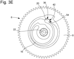
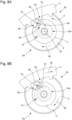
- the clockwork movement 62 is characterized firstly by the fact that the rigid element of the mechanism 60 is a lever 66 which is mounted on a plate 11, which the mechanism comprises.
- the plate 11 has a circular central hole 34A and is guided in rotation, around the axis of rotation 22 which is a first axis of rotation, relative to the wheel plate 8 by the shaft 28 to which this wheel plate is fixed.
- the lever 66 is mounted on the plate 11 so as to be movable in rotation around a second axis of rotation 72 which is distant from the first axis of rotation 22, the second axis of rotation being arranged at a first end of the lever.
- the rocker is formed by an arm 67 comprising at its first end a stud 74, inserted into a corresponding hole in the plate 11 so as to be able to pivot around the second axis of rotation 72, and on the side of its second end a drive finger 68 and an internal part defining a proper housing 76 for a coupling member 70 and comprising a front part 78 which defines a stress ramp 80 for the spring 16A (elements which will be described in more detail later).
- the mechanism 60 also comprises a stop 90 which is integral with the plate 11 and which limits the rotation of the rocker 66 in a first direction of rotation corresponding to a radial distance of the drive finger relative to the first axis of rotation 22.
- the plate 11 has a lateral surface, one zone of which defines the stop 90, the drive finger 68 being arranged in such a way that a rear upper portion 92 of this finger can come to bear against the stop 90, so as to be held in a fixed angular position relative to the second axis of rotation and thus in a fixed position relative to the first axis of rotation, in particular when driving the indicator 4 ( Figures 8B ) or, in the context of the present invention, when the coupling member 70 follows said at least one terminal section of the constraint ramp 80 ( Figures 7D And 7th ), as will be further explained later.
- the stress ramp 80 is arranged in such a way that, when the coupling member 70 follows this stress ramp while approaching the housing 76 itself, the coupling member exerts on the rocker 66 a torque in the first direction of rotation and the coupling member 70 undergoes, at least on a terminal section of the stress ramp, a radial displacement in a radial direction D2 towards the first axis of rotation 22, while the rocker is bearing against the stop 90 and the spring 16A is stressed.
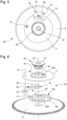
- the first end 17 of the spring 16A is connected to a central rigid ring 24A while the second end 19 carries the coupling member 70.
- the spring comprises a coil 18A which has on the side of the second end an internal projecting part 82, which is intended to stop the contraction stress of the spring, that is to say of its coil 18A, when the mechanism 60 is mounted in the watch movement 62 and works, as shown in Figures 8A and 8B , which are similar to the Figures 4A and 4B relating to the first embodiment.
- Figures 8A and 8B show the mechanism 60 and the date ring 4, comprising a toothing 5, during a drive of this ring for the passage to a following date at midnight, respectively: - At the moment when the drive finger 68 comes into contact against a tooth 5a of the ring and when the spring 16A is substantially angularly relaxed (i.e.
- the plate 11 and the rocker 66 are arranged so that the rocker can undergo, from a first position where the rocker 66 is bearing against the stop 90, a rotation in the second direction of rotation, opposite to the first direction of rotation, to a second position where the drive finger 68 is retracted/withdrawn on the side of the first axis of rotation 22.
- the constraint ramp 80 is configured so that, during the relative movement MR between the rocker and the wheel board 8 while the spring 16A is relaxed/unstressed and the rocker is located in the second position, the coupling member 70 can come to bear against the constraint ramp 80 ( Figure 7B ) to then be able to follow this constraint ramp while approaching the own housing 76 ( Figures 7C to 7E ).
- a step of positioning the rocker can take place before the coupling step, this positioning step consisting of putting the rocker in contact with the stop 90, that is to say in its first position, before carrying out the relative movement MR between the wheel board 8 and the plate 11.
- the coupling member 70 undergoes a displacement relative to the support, called relative displacement, in the second direction D2 towards the axis of rotation 22 and the spring 16A is stressed only when the coupling member 70 continues to follow / climb the stress ramp on a second section, located after the first section on the side of the housing 76 ( Figure 7E ), after the rocker 66 has come to rest against the stop 90 ( Figure 7D ).
- the coupling member 70 enters its own housing 76 through its lateral opening, while the spring undergoes a rapid partial relaxation, and said relative movement is terminated by a small recoil, in the opposite direction to the direction occurring when the coupling member climbs the stress ramp, to allow this member to reach the intended coupling position ( Figure 7F ).
- the spring can still be slightly radially stressed or radially relaxed. In the absence of a force moment exerted on the coupling member, the spring is then in the latter case completely relaxed.
- this relative movement MR is more complex because the rocker rotates progressively around its own axis 72 until it comes to bear against the stop 90.
- the relative movement MR continues to have a component in said angular direction D1, namely a guided rotation around the central axis 22 which is necessary, but there also appears a component relating to the rotation of the rocker 66 around its axis 72.
- This second phase will also be called 'initial phase', which is indeed an initial phase in relation to the fact that the coupling member follows / climbs the constraint ramp.
- the coupling member 70 could theoretically come out of its own housing 76. But during such corrections, the drive finger and the coupling member undergo a recoil towards the central axis, contrary to what happens during the coupling process.
- the coupling member 70 follows the inner flank 88 of the lever 66 and the coupling member automatically arrives in the proper housing 76 and in the intended coupling position. Then, the spring 16A can be loaded in contraction as intended to be able to perform a jump drive of the indicator 4.
- the operating test of the mechanism 60 will require modifying the positioning of the minute hand on its axis if this hand has already been mounted before this test for the jump drive of the indicator.
Landscapes
- Physics & Mathematics (AREA)
- General Physics & Mathematics (AREA)
- Engineering & Computer Science (AREA)
- Manufacturing & Machinery (AREA)
- Electromechanical Clocks (AREA)
- Connection Of Plates (AREA)
- Devices For Conveying Motion By Means Of Endless Flexible Members (AREA)
Applications Claiming Priority (1)
| Application Number | Priority Date | Filing Date | Title |
|---|---|---|---|
| EP23219470 | 2023-12-21 |
Publications (1)
| Publication Number | Publication Date |
|---|---|
| EP4575676A1 true EP4575676A1 (de) | 2025-06-25 |
Family
ID=89321722
Family Applications (1)
| Application Number | Title | Priority Date | Filing Date |
|---|---|---|---|
| EP24207292.4A Pending EP4575676A1 (de) | 2023-12-21 | 2024-10-17 | Uhrwerk, das ein starres bewegliches element umfasst, das mit einem elastischen element gekoppelt ist, und verfahren zum verbinden dieser elemente |
Country Status (5)
| Country | Link |
|---|---|
| US (1) | US20250208576A1 (de) |
| EP (1) | EP4575676A1 (de) |
| JP (1) | JP7789163B2 (de) |
| KR (1) | KR20250097665A (de) |
| CN (2) | CN120195947A (de) |
Citations (4)
| Publication number | Priority date | Publication date | Assignee | Title |
|---|---|---|---|---|
| CH700662A1 (fr) * | 2009-03-25 | 2010-09-30 | Hublot Sa Geneve | Mécanisme d'entraînement instantané d'un indicateur de quantième. |
| EP2392975B1 (de) * | 2010-06-03 | 2019-05-15 | Patek Philippe SA Genève | Drehorgan mit unidirektionaler Kupplung |
| EP3822710A1 (de) * | 2019-11-13 | 2021-05-19 | Patek Philippe SA Genève | Unidirektionale kupplungsfeder, insbesondere für uhrwerk |
| EP3828644A1 (de) | 2019-11-27 | 2021-06-02 | ETA SA Manufacture Horlogère Suisse | Uhrwerkdrehteil für semi-momentaner sprungmechanismus |
-
2024
- 2024-10-17 EP EP24207292.4A patent/EP4575676A1/de active Pending
- 2024-11-11 US US18/942,985 patent/US20250208576A1/en active Pending
- 2024-11-13 JP JP2024198210A patent/JP7789163B2/ja active Active
- 2024-11-21 KR KR1020240167416A patent/KR20250097665A/ko active Pending
- 2024-12-03 CN CN202411760026.6A patent/CN120195947A/zh active Pending
- 2024-12-03 CN CN202422972554.XU patent/CN224005416U/zh active Active
Patent Citations (4)
| Publication number | Priority date | Publication date | Assignee | Title |
|---|---|---|---|---|
| CH700662A1 (fr) * | 2009-03-25 | 2010-09-30 | Hublot Sa Geneve | Mécanisme d'entraînement instantané d'un indicateur de quantième. |
| EP2392975B1 (de) * | 2010-06-03 | 2019-05-15 | Patek Philippe SA Genève | Drehorgan mit unidirektionaler Kupplung |
| EP3822710A1 (de) * | 2019-11-13 | 2021-05-19 | Patek Philippe SA Genève | Unidirektionale kupplungsfeder, insbesondere für uhrwerk |
| EP3828644A1 (de) | 2019-11-27 | 2021-06-02 | ETA SA Manufacture Horlogère Suisse | Uhrwerkdrehteil für semi-momentaner sprungmechanismus |
Also Published As
| Publication number | Publication date |
|---|---|
| JP2025100363A (ja) | 2025-07-03 |
| US20250208576A1 (en) | 2025-06-26 |
| KR20250097665A (ko) | 2025-06-30 |
| JP7789163B2 (ja) | 2025-12-19 |
| CN120195947A (zh) | 2025-06-24 |
| CN224005416U (zh) | 2026-03-17 |
Similar Documents
| Publication | Publication Date | Title |
|---|---|---|
| CH709508A2 (fr) | Mouvement horloger muni d'un mécanisme d'entraînement d'un indicateur analogique à déplacement périodique ou intermittent. | |
| EP2264551B1 (de) | Differentialzahnradgetriebe für Uhrwerk | |
| EP1978420A1 (de) | Vorrichtung zur Korrektur eines Anzeigemechanismus für eine Uhr und Rad zur Ausstattung einer solchen Vorrichtung | |
| EP4231100B1 (de) | Vorrichtung zur steuerung für uhren | |
| EP4575676A1 (de) | Uhrwerk, das ein starres bewegliches element umfasst, das mit einem elastischen element gekoppelt ist, und verfahren zum verbinden dieser elemente | |
| CH721446A2 (fr) | Mouvement horloger comprenant un élément rigide mobile accouplé à un élément élastique et procédé d'accouplement de ces deux éléments | |
| EP1213626A1 (de) | Stossfeste Übertragungsmittel zum Antrieb eines Generators durch eine Schwungmasse, insbesondere in einer Uhr | |
| EP1923754B1 (de) | Mit einem Anzeigemodul ausgerüstetes Uhrwerk | |
| CH720210B1 (fr) | Mouvement horloger comprenant un mécanisme de commande de quantième | |
| CH720214B1 (fr) | Mécanisme de commande de quantième d'un mouvement horloger | |
| EP4462193B1 (de) | Mechanisches uhrwerk, das ein bewegliches element umfasst, das ein anzeigeelement mit einer bremsvorrichtung umfasst | |
| EP1960846B1 (de) | Uhrwerk | |
| EP1960848B1 (de) | Hammer einer uhr | |
| EP4575674A1 (de) | Uhrwerk, das mit einem antriebsmechanismus eines sprunganzeigers ausgestattet ist | |
| EP4575673A1 (de) | Uhrwerk, das mit einem antriebsmechanismus eines sschrittanzeigers ausgestattet ist | |
| CH720774A2 (fr) | Mouvement horloger mécanique comprenant un mobile portant un organe d'affichage et muni d'un dispositif de freinage | |
| EP4575657A1 (de) | Vorrichtung zur zeiteinstellung einer uhrwerke | |
| EP4625066A1 (de) | Elektromechanische uhrwerk, das ein bewegliches element umfasst, das ein anzeigeelement mit einer bremsvorrichtung umfasst | |
| CH721682A2 (fr) | Mouvement horloger électromécanique comprenant un mobile portant un organe d'affichage et muni d'un dispositif de freinage | |
| EP3742236B1 (de) | Uhrvorrichtung, die eine erste komponente umfasst, die auf einer zweiten komponente durch plastische verformung fixiert ist | |
| EP4280002A1 (de) | Chronographenmodul mit einem abnehmbaren rad | |
| CH721440A2 (fr) | Mouvement horloger muni d'un mécanisme d'entrainement d'un indicateur sautant | |
| CH721444A2 (fr) | Mouvement horloger muni d'un mécanisme d'entrainement d'un indicateur sautant | |
| EP1925996A1 (de) | Vorrichtung zur Korrektur eines Anzeigemechanismus für eine Uhr | |
| EP4579360A1 (de) | Haltevorrichtung für ein mobiles gerät |
Legal Events
| Date | Code | Title | Description |
|---|---|---|---|
| PUAI | Public reference made under article 153(3) epc to a published international application that has entered the european phase |
Free format text: ORIGINAL CODE: 0009012 |
|
| STAA | Information on the status of an ep patent application or granted ep patent |
Free format text: STATUS: THE APPLICATION HAS BEEN PUBLISHED |
|
| AK | Designated contracting states |
Kind code of ref document: A1 Designated state(s): AL AT BE BG CH CY CZ DE DK EE ES FI FR GB GR HR HU IE IS IT LI LT LU LV MC ME MK MT NL NO PL PT RO RS SE SI SK SM TR |
|
| P01 | Opt-out of the competence of the unified patent court (upc) registered |
Free format text: CASE NUMBER: APP_31979/2025 Effective date: 20250702 |
|
| STAA | Information on the status of an ep patent application or granted ep patent |
Free format text: STATUS: REQUEST FOR EXAMINATION WAS MADE |
|
| 17P | Request for examination filed |
Effective date: 20260102 |