EP4575691A1 - Surveillance d'équipement de sous-station à l'aide d'un système scada - Google Patents
Surveillance d'équipement de sous-station à l'aide d'un système scada Download PDFInfo
- Publication number
- EP4575691A1 EP4575691A1 EP25163113.1A EP25163113A EP4575691A1 EP 4575691 A1 EP4575691 A1 EP 4575691A1 EP 25163113 A EP25163113 A EP 25163113A EP 4575691 A1 EP4575691 A1 EP 4575691A1
- Authority
- EP
- European Patent Office
- Prior art keywords
- attention
- attention indicator
- values
- data
- substation equipment
- Prior art date
- Legal status (The legal status is an assumption and is not a legal conclusion. Google has not performed a legal analysis and makes no representation as to the accuracy of the status listed.)
- Pending
Links
Images


Classifications
-
- G—PHYSICS
- G05—CONTROLLING; REGULATING
- G05B—CONTROL OR REGULATING SYSTEMS IN GENERAL; FUNCTIONAL ELEMENTS OF SUCH SYSTEMS; MONITORING OR TESTING ARRANGEMENTS FOR SUCH SYSTEMS OR ELEMENTS
- G05B23/00—Testing or monitoring of control systems or parts thereof
- G05B23/02—Electric testing or monitoring
- G05B23/0205—Electric testing or monitoring by means of a monitoring system capable of detecting and responding to faults
- G05B23/0218—Electric testing or monitoring by means of a monitoring system capable of detecting and responding to faults characterised by the fault detection method dealing with either existing or incipient faults
- G05B23/0221—Preprocessing measurements, e.g. data collection rate adjustment; Standardization of measurements; Time series or signal analysis, e.g. frequency analysis or wavelets; Trustworthiness of measurements; Indexes therefor; Measurements using easily measured parameters to estimate parameters difficult to measure; Virtual sensor creation; De-noising; Sensor fusion; Unconventional preprocessing inherently present in specific fault detection methods like PCA-based methods
-
- G—PHYSICS
- G05—CONTROLLING; REGULATING
- G05B—CONTROL OR REGULATING SYSTEMS IN GENERAL; FUNCTIONAL ELEMENTS OF SUCH SYSTEMS; MONITORING OR TESTING ARRANGEMENTS FOR SUCH SYSTEMS OR ELEMENTS
- G05B2219/00—Program-control systems
- G05B2219/30—Nc systems
- G05B2219/32—Operator till task planning
- G05B2219/32404—Scada supervisory control and data acquisition
Definitions
- Embodiments presented herein relate to a method, a Supervisory Control And Data Acquisition (SCADA) system, a computer program, and a computer program product for monitoring substation equipment.
- SCADA Supervisory Control And Data Acquisition
- Substation equipment such as transformers, circuit breakers, etc. are traditionally monitored by dedicated hardware, software and own interface to provide results, warnings and alarms to the user.
- the general understanding is that data processing and analysis should be performed locally in the monitoring hardware and the results should be available on the local Human-Machine Interface (HMI) or remotely through web interfaces.
- HMI Human-Machine Interface
- Substation SCADA systems are currently used either to just tunnel data to other analysis platforms or present status from monitoring equipment.
- An object of embodiments herein is to provide efficient monitoring of substation equipment.
- a method for monitoring substation equipment The method is performed by a SCADA system.
- the method comprises obtaining parameter values from data/signal values pertaining to parameters monitored in the substation equipment.
- the method comprises associating each of at least some of the parameter values with at least one attention indicator.
- the method comprises determining one attention indicator value for each of the attention indicators by processing those parameter values that are associated with the respective attention indicators. All attention indicators for all monitored parameter have one and the same nominal attention indicator value acting as a threshold for abnormal behavior of the substation equipment.
- the method comprises providing an alert indication to an HMI when at least one of the attention indicator values is above the nominal attention indicator value.
- a SCADA system for monitoring substation equipment.
- the SCADA system comprises processing circuitry.
- the processing circuitry is configured to cause the SCADA system to obtain parameter values from data/signal values pertaining to parameters monitored in the substation equipment.
- the processing circuitry is configured to cause the SCADA system to associate each of at least some of the parameter values with at least one attention indicator.
- the processing circuitry is configured to cause the SCADA system to determine one attention indicator value for each of the attention indicators by processing those parameter values that are associated with the respective attention indicators. All attention indicators for all monitored parameter have one and the same nominal attention indicator value acting as a threshold for abnormal behavior of the substation equipment.
- the processing circuitry is configured to cause the SCADA system to provide an alert indication to an HMI when at least one of the attention indicator values is above the nominal attention indicator value.
- a computer program for monitoring substation equipment comprising computer program code which, when run on a SCADA system, causes the SCADA system to perform a method according to the first aspect.
- a computer program product comprising a computer program according to the third aspect and a computer readable storage medium on which the computer program is stored.
- the computer readable storage medium could be a non-transitory computer readable storage medium.
- Fig. 1 is a schematic diagram illustrating a monitoring system 100 where embodiments presented herein can be applied.
- the monitoring system 100 comprises a SCADA system 200.
- the SCADA system comprises a SCADA software entity 140, a communication driver 150, a local storage 160, and a pre-processing block 170.
- the SCADA software entity 140 comprises process object storage 141, an HMI 142, data object storage 143, a data acquisition (DA) client 144, a data analysis block 145, a log 146, and an event generator 147.
- the SCADA system 200 is operatively connected to a piece of substation equipment 110, a historian 120, and a fleet management entity 130. As the skilled person understands, there might be a plurality of pieces of substation equipment 110 in the monitoring system 100 to which the SCADA system 200 is operatively connected.
- Processed or raw monitoring signals/data values (e.g. representing values of signals and/or data from sensors, monitoring IEDs, protection IEDs, etc.) of one or more pieces of substation equipment 110 (hereinafter for brevity referred to as "substation equipment 110") are provided to the SCADA system 200 based on standard substation communication protocols like IEC 61850-8-1, Modbus, the Distributed Network Protocol (DNP), etc.
- the signal/data values might be received at the communication driver 150, such as an OPC (OLE for Process Control, where OLE is short for Object Linking and Embedding) server in the SCADA system 200.
- OPC OPC
- OPC is a software interface standard that allows Windows programs to communicate with industrial hardware devices. OPC is implemented in server/client pairs.
- the communication driver 150 may be provided as a software program that converts the hardware communication protocol used by a programmable logic controller (PLC) into the OPC protocol, or the like.
- PLC programmable logic controller
- the communication driver 150 provides the data/signals to the local storage 160 and the OPC DA client 144.
- substation SCADA systems 200 have the potential to host monitoring algorithms of different kind (performing pre-processing, processing and data analysis) and to aggregate all monitored information to provide a common interface to the user/operator alongside control and protection information, they are currently used either to just tunnel data to other analysis platforms or present status from monitoring equipment.
- the embodiments disclosed herein therefore relate to mechanisms for monitoring substation equipment 110.
- a SCADA system 200 a method performed by the SCADA system 200, a computer program product comprising code, for example in the form of a computer program, that when run on a SCADA system 200, causes the SCADA system 200 to perform the method.
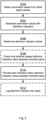
- Fig. 2 is a flowchart illustrating embodiments of methods for monitoring substation equipment 110. The methods are performed by the SCADA system 200. The methods are advantageously provided as computer programs 620.
- the SCADA system 200 obtains parameter values from data/signal values pertaining to parameters monitored in the substation equipment 110. How the SCADA system 200 might obtain signals/data values from the substation equipment 110 has been disclosed above.
- Each parameter value could be directly obtained from one or more data/signal values but also be the result of a combination of one or more pre-processed data/signal values. Further, each data/signal value could be mapped to one or more parameter values.
- S104 The SCADA system 200 associates each of at least some of the parameter values with at least one attention indicator. S104 might be implemented by the data analysis block 145.
- S106 The SCADA system 200 determines one attention indicator value for each of the attention indicators by processing those parameter values that are associated with the respective attention indicators. S106 might be implemented by the data analysis block 145.
- All attention indicators for all monitored parameter have one and the same nominal attention indicator value acting as a threshold for abnormal behavior of the substation equipment 110.
- S110 The SCADA system 200 provides an alert indication to the HMI 142 when at least one of the attention indicator values is above the nominal attention indicator value.
- S110 might be implemented by the data analysis block 145 in conjunction with the HMI 142.
- the parameter to be monitored is the total power loss in a transformer application, and that 12 waveforms (6 voltage waveforms and 6 corresponding current waveforms) are measured. From each of these waveforms, the fundamental frequency phasor (amplitude and phase angle, given as a complex number) is extracted during pre-processing and sent to the SCADA system 200. Thus, in total 24 data/signal values (one amplitude value and one phase angle value for each of the 12 waveforms) are provided and obtained by the SCADA system 200.
- the total power loss is then obtained by multiplying each voltage phasor with the complex conjugate of the corresponding current phasor, obtaining the phase power, then summing the phase powers on the high voltage side to obtain the total power of the transformer and the same for the low voltage side, and then taking the difference between the total power in and out of the transformer to obtain the total power loss.
- This difference is then the basis for one attention indicator.
- the phasors, or the waveforms they represent are the data/signal values; the total power loss is one example of a parameter.
- the same 12 complex phasors can be used various combinations to determine also other parameter values and attention indicators.
- parts of the herein disclosed embodiments are implemented in the SCADA software entity 140 of the SCADA system 200 to provide a standardized solution for uniform substation equipment monitoring, by using programming capabilities provided for in the SCADA software entity 140 for pre-processing, processing and analysis of monitored parameters. Furthermore, detailed and fast health status presentation (so-called dialogs) to the user can be built using the visual programming environment of the SCADA software entity 140.
- the substation equipment 110 might comprise sensors, monitoring IEDs, and/or protection IEDs.
- the data/signal values might then be obtained from the sensors, monitoring IEDs, and/or protection IEDs.
- there are at least as many attention indicators as there are monitored parameters in practice there could be more attention indicators than monitored parameters. That is, if there are 20 parameters in the subsystem equipment that are monitored, then there are 20 attention indicators or more. However, this does not necessarily mean that 20 data/signal values are obtained per time unit (which in turn are mapped to at least 20 attention indicator values); the data/signal values could be obtained with different relative frequencies (such as depending on individual sampling periods in the substation equipment 110, the protocol according to which the data/signal values are obtained by the SCADA system 200 from the substation equipment 110, etc.). Further, some data/signal values, such as values from tap operations, are only available at irregular time intervals.
- the data/signal values are pre-processed in the SCADA system 200, such as in the pre-processing block 170 that fetches the data/signal values from the local storage 160, before being associated with the parameter values.
- the signal/data values may be directly linked to the analysis routines in SCADA software (via the DA client 144) or passed through a pre-processing stage to extract relevant parameter values.
- pre-processing means are waveform analysis algorithms that extract parameter values from waveforms such as amplitudes, operation times and more. Processor and memory intensive complex pre-processing algorithms can be hosted in hardware of the SCADA system 200 and the rest of analysis routines can be coded and hosted within the software environment of the SCADA system 200.
- the data/signal values are pre-processed by being scaled such that a nominal value of each parameter value is associated with the nominal attention indicator value.
- the attention indicator values per monitored parameter might thus be scaled quantities based on the data/signal values.
- the data/signal values are scaled with a monitored parameter dependent scaling function.
- the nominal attention indicator value acts as a threshold for abnormal behavior of the substation equipment 110. Further, all attention indicators have one and the same nominal attention indicator value. In some examples the nominal attention indicator value is 1.0. Thus, an attention indicator value 1.0 means that the parameter values of that attention indicator is exactly on the allowed limit (regardless of the actual value of the parameter values). This makes it easy to condense all of the individual attention indicator values into one single main individual attention indicator value by taking the largest value in any of them. In some examples it is thus enough just to check the attention indicator having the largest value. That is, according to an embodiment the SCADA system 200 is configured to perform S108: S108: The SCADA system 200 checks only whether the largest of all the attention indicator values exceeds the nominal attention indicator value or not. S108 might be implemented by the data analysis block 145.
- an alert indication is provided for each attention indicator whose value exceeds the nominal attention indicator value and then the values of all the attention indicators need to be checked.
- the attention indicators are linked to the event handing database of the SCADA system 200, which generates and logs events of the monitored parameters. That is, according to an embodiment the SCADA system 200 is configured to perform S112: S112: The SCADA system 200 logs each at least one attention indicator (and its value) whose attention indicator value exceeds a particular value. This particular value might be equal to the nominal attention indicator value, or be an integer factor of the nominal attention indicator value. In some examples the logged attention indicator (and its value) is timestamped. The at least one attention indicator (and its value) might be logged in the log 146.
- the monitored parameters and analysis results might thereby be available in a standard format if there is a need for communicating them to asset management or fleet assessment system, such as the historian 120 or the fleet management entity 130.
- the alert indication is an alarm when at least one of the attention indicator values is at least three times the nominal attention indicator value.
- the alarm might be triggered as an event generated in the event block 147 in conjunction with the data analysis block 145.
- each parameter corresponds to one respective attention indicator (although in practice, it could typically be that one monitored parameter is associated with two or more attention indicators and that there are more attention indicators than monitored parameters).
- the parameter relating to temperature has a nominal value of 20 degrees Celsius that corresponds to the nominal attention indicator value 1.0
- the parameter relating to the first voltage has a nominal value of 15 V that corresponds to the nominal attention indicator value 1.0
- the parameter relating to the second voltage has a nominal value of 120 V that corresponds to the nominal attention indicator value 1.0.
- a data/signal value of 15 degrees Celsius for the parameter relating to temperature would be mapped to an attention indicator value below 1.0
- a data/signal value of 120 V for the parameter relating to the first voltage would be mapped to an attention indicator value above 1.0
- a data/signal value of 90 V for the parameter relating to the second voltage would be mapped to an attention indicator value below 1.0.
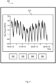
- a detailed view of analyzed monitoring parameter values, warnings, alarms, etc. might be available to the user through a display at the HMI 142.
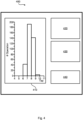
- This view could include history of input data to the analysis algorithms in the SCADA system 200, monitored parameters with their trends and set limits, results in different formats (like tables, pie charts, bar graphs, etc.).
- Fig. 3 and Fig. 4 show an example in the form of screen captures 300, 400 where a substation infrastructure is used to build a complete transformer monitoring system based on voltage and current signals available in protection IEDs.
- Fig. 3 schematically illustrates a display 310 and HMI components 320, 330, 340, 350 which could symbolize any combination of buttons, displays, menu items, lists, etc.
- Fig. 4 schematically illustrates a display 410 and HMI components 420, 430, 440 which could symbolize any combination of buttons, displays, menu items, lists, etc.
- Pre-processing, processing and analysis of data is performed in the SCADA system 200.
- transformer performance immpedance, turn ratio, magnetizing current and power loss
- Fig. 4 are monitored based on phasor and waveform analysis performed in the pre-processing entity 170 and SCADA software entity 140.
- Fig. 5 schematically illustrates, in terms of a number of functional units, the components of a SCADA system 200 according to an embodiment.
- Processing circuitry 210 is provided using any combination of one or more of a suitable central processing unit (CPU), multiprocessor, microcontroller, digital signal processor (DSP), etc., capable of executing software instructions stored in a computer program product 610 (as in Fig. 6 ), e.g. in the form of a storage medium 230.
- the processing circuitry 210 may further be provided as at least one application specific integrated circuit (ASIC), or field programmable gate array (FPGA).
- ASIC application specific integrated circuit
- FPGA field programmable gate array
- the processing circuitry 210 is configured to cause the SCADA system 200 to perform a set of operations, or actions, as disclosed above.
- the storage medium 230 may store the set of operations
- the processing circuitry 210 may be configured to retrieve the set of operations from the storage medium 230 to cause the SCADA system 200 to perform the set of operations.
- the set of operations may be provided as a set of executable instructions.
- the processing circuitry 210 is thereby arranged to execute methods as herein disclosed.
- the storage medium 230 may also comprise persistent storage, which, for example, can be any single one or combination of magnetic memory, optical memory, solid state memory or even remotely mounted memory.
- the SCADA system 200 may further comprise a communications interface 220 at least configured for communications with other entities, systems, functions, nodes, devices, and equipment. As such the communications interface 220 may comprise one or more transmitters and receivers, comprising analogue and digital components.
- the processing circuitry 210 controls the general operation of the SCADA system 200 e.g. by sending data and control signals to the communications interface 220 and the storage medium 230, by receiving data and reports from the communications interface 220, and by retrieving data and instructions from the storage medium 230.
- Other components, as well as the related functionality, of the SCADA system 200 are omitted in order not to obscure the concepts presented herein.
- the processing circuitry 210, the storage medium 230, and the communications interface 220 collectively implements the functionality of the SCADA system 200 of Fig. 1 .
- Fig. 6 shows one example of a computer program product 610 comprising computer readable storage medium 630.
- a computer program 620 can be stored, which computer program 620 can cause the processing circuitry 210 and thereto operatively coupled entities and devices, such as the communications interface 220 and the storage medium 230, to execute methods according to embodiments described herein.
- the computer program 620 and/or computer program product 610 may thus provide means for performing any actions as herein disclosed.
Landscapes
- Physics & Mathematics (AREA)
- General Physics & Mathematics (AREA)
- Engineering & Computer Science (AREA)
- Automation & Control Theory (AREA)
- Remote Monitoring And Control Of Power-Distribution Networks (AREA)
- Testing And Monitoring For Control Systems (AREA)
Priority Applications (1)
| Application Number | Priority Date | Filing Date | Title |
|---|---|---|---|
| EP25163113.1A EP4575691A1 (fr) | 2019-04-24 | 2019-04-24 | Surveillance d'équipement de sous-station à l'aide d'un système scada |
Applications Claiming Priority (2)
| Application Number | Priority Date | Filing Date | Title |
|---|---|---|---|
| EP25163113.1A EP4575691A1 (fr) | 2019-04-24 | 2019-04-24 | Surveillance d'équipement de sous-station à l'aide d'un système scada |
| EP19170849.4A EP3731049B1 (fr) | 2019-04-24 | 2019-04-24 | Surveillance d'équipement de sous-station à l'aide d'un système scada |
Related Parent Applications (2)
| Application Number | Title | Priority Date | Filing Date |
|---|---|---|---|
| EP19170849.4A Division-Into EP3731049B1 (fr) | 2019-04-24 | 2019-04-24 | Surveillance d'équipement de sous-station à l'aide d'un système scada |
| EP19170849.4A Division EP3731049B1 (fr) | 2019-04-24 | 2019-04-24 | Surveillance d'équipement de sous-station à l'aide d'un système scada |
Publications (1)
| Publication Number | Publication Date |
|---|---|
| EP4575691A1 true EP4575691A1 (fr) | 2025-06-25 |
Family
ID=66251684
Family Applications (2)
| Application Number | Title | Priority Date | Filing Date |
|---|---|---|---|
| EP19170849.4A Active EP3731049B1 (fr) | 2019-04-24 | 2019-04-24 | Surveillance d'équipement de sous-station à l'aide d'un système scada |
| EP25163113.1A Pending EP4575691A1 (fr) | 2019-04-24 | 2019-04-24 | Surveillance d'équipement de sous-station à l'aide d'un système scada |
Family Applications Before (1)
| Application Number | Title | Priority Date | Filing Date |
|---|---|---|---|
| EP19170849.4A Active EP3731049B1 (fr) | 2019-04-24 | 2019-04-24 | Surveillance d'équipement de sous-station à l'aide d'un système scada |
Country Status (5)
| Country | Link |
|---|---|
| US (1) | US20220206482A1 (fr) |
| EP (2) | EP3731049B1 (fr) |
| JP (1) | JP7232936B2 (fr) |
| CN (1) | CN113748390A (fr) |
| WO (1) | WO2020216723A1 (fr) |
Families Citing this family (3)
| Publication number | Priority date | Publication date | Assignee | Title |
|---|---|---|---|---|
| CN115048965B (zh) * | 2022-08-15 | 2022-12-13 | 南方医科大学珠江医院 | 超声波医疗设备的故障检测方法、装置、设备及介质 |
| CN118974668A (zh) * | 2023-03-14 | 2024-11-15 | 东芝三菱电机产业系统株式会社 | Scada网页hmi系统 |
| US20250278126A1 (en) * | 2024-03-01 | 2025-09-04 | Ge Infrastructure Technology Llc | Enhanced power substation digital twins |
Citations (2)
| Publication number | Priority date | Publication date | Assignee | Title |
|---|---|---|---|---|
| EP2363773A2 (fr) * | 2010-02-26 | 2011-09-07 | General Electric Company | Systèmes et procédés de surveillance de l'état des équipements dans une installation d'alimentation électrique |
| EP3023851A1 (fr) * | 2014-11-18 | 2016-05-25 | General Electric Company | Système et procédé permettant de déterminer l'état de santé actuel et futur d'un transformateur de puissance |
Family Cites Families (12)
| Publication number | Priority date | Publication date | Assignee | Title |
|---|---|---|---|---|
| JPS57168307A (en) * | 1981-04-08 | 1982-10-16 | Hitachi Ltd | Detecting system for state change of electric power system |
| US7676285B2 (en) * | 2004-04-22 | 2010-03-09 | General Electric Company | Method for monitoring driven machinery |
| US7558703B2 (en) * | 2006-11-01 | 2009-07-07 | Abb Research Ltd. | Electrical substation monitoring and diagnostics |
| CN102193555B (zh) * | 2011-03-11 | 2013-04-17 | 凯里供电局 | 集控中心全景状态监测系统 |
| US9627886B2 (en) * | 2012-03-27 | 2017-04-18 | Mitsubishi Electric Research Laboratoriies, Inc. | State estimation for power system using hybrid measurements |
| US9405291B2 (en) | 2012-07-31 | 2016-08-02 | Fisher-Rosemount Systems, Inc. | Systems and methods to monitor an asset in an operating process unit |
| JP5952127B2 (ja) * | 2012-08-08 | 2016-07-13 | 株式会社日立製作所 | 配電系統の断線事故検出方法および配電設備管理システム |
| US11232649B2 (en) | 2014-05-19 | 2022-01-25 | Pas, Inc. | Method and system for automation, safety and reliable operation performance assessment |
| US20160327600A1 (en) * | 2015-05-04 | 2016-11-10 | General Electric Company | Integrated transformer health monitoring architecture |
| JP6604076B2 (ja) * | 2015-07-29 | 2019-11-13 | 東京電力ホールディングス株式会社 | 監視制御システム |
| WO2017205238A1 (fr) | 2016-05-23 | 2017-11-30 | Lin And Associates, Inc | Sensibilisation progressive dynamique |
| CN109214536A (zh) * | 2018-11-22 | 2019-01-15 | 广东电网有限责任公司 | 一种设备健康状态评估方法 |
-
2019
- 2019-04-24 EP EP19170849.4A patent/EP3731049B1/fr active Active
- 2019-04-24 EP EP25163113.1A patent/EP4575691A1/fr active Pending
-
2020
- 2020-04-20 WO PCT/EP2020/061016 patent/WO2020216723A1/fr not_active Ceased
- 2020-04-20 CN CN202080030504.1A patent/CN113748390A/zh active Pending
- 2020-04-20 US US17/605,974 patent/US20220206482A1/en active Pending
- 2020-04-20 JP JP2021562394A patent/JP7232936B2/ja active Active
Patent Citations (2)
| Publication number | Priority date | Publication date | Assignee | Title |
|---|---|---|---|---|
| EP2363773A2 (fr) * | 2010-02-26 | 2011-09-07 | General Electric Company | Systèmes et procédés de surveillance de l'état des équipements dans une installation d'alimentation électrique |
| EP3023851A1 (fr) * | 2014-11-18 | 2016-05-25 | General Electric Company | Système et procédé permettant de déterminer l'état de santé actuel et futur d'un transformateur de puissance |
Also Published As
| Publication number | Publication date |
|---|---|
| JP7232936B2 (ja) | 2023-03-03 |
| EP3731049A1 (fr) | 2020-10-28 |
| EP3731049B1 (fr) | 2025-04-16 |
| JP2022530005A (ja) | 2022-06-27 |
| US20220206482A1 (en) | 2022-06-30 |
| CN113748390A (zh) | 2021-12-03 |
| WO2020216723A1 (fr) | 2020-10-29 |
Similar Documents
| Publication | Publication Date | Title |
|---|---|---|
| EP3411723B1 (fr) | Dispositif et procédé de surveillance et de diagnostic de santé de transformateur | |
| US20220206482A1 (en) | Substation equipment monitoring using a scada system | |
| CN104538233A (zh) | 变电站电动刀闸状态监测预警系统及方法 | |
| EP3602715B1 (fr) | Système, procédé et produit programme d'ordinateur d'analyse de défaillance améliorée d'un système d'alimentation électrique | |
| JP6474894B2 (ja) | データ収集システムおよび方法、計測データ量の削減方法 | |
| US20190079129A1 (en) | Methods and systems for ground fault detection in a power distribution system | |
| US20160054364A1 (en) | Power monitoring system for a power system, and power monitoring device thereof | |
| CN115136435A (zh) | 具有现场维修能力的断路器 | |
| CN110134709B (zh) | 电网数据查询方法及装置 | |
| CN104935076A (zh) | 能源管理系统的数据处理装置 | |
| JP2019135467A (ja) | 故障診断システム | |
| CN107527134A (zh) | 一种基于大数据的配电变压器状态评估方法及装置 | |
| CN113391567A (zh) | 一种基于物联网的智能控制机构 | |
| CN110553830B (zh) | 一种金属封闭开关设备机械特性在线检测方法 | |
| CN119471146B (zh) | 一种高压开关柜故障监测系统及方法 | |
| KR102818031B1 (ko) | 디지털 변전소의 감시진단장치 및 그 제어방법 | |
| CN118707427B (zh) | 磁阀式电流互感器运行状态判断方法、装置及电子设备 | |
| KR101861576B1 (ko) | Iec61850 기반 현장정보 처리반 | |
| KR101309400B1 (ko) | 주파수보호 기능을 가진 머징유닛 | |
| US12055576B2 (en) | Calculating electric power noise distributions | |
| US9836072B2 (en) | Data processing apparatus of energy management system | |
| CN114152827A (zh) | 一种高压配电柜的运行监控方法、系统、装置及存储介质 | |
| CN113765062A (zh) | 一种电动机故障诊断和保护控制系统 | |
| CN119667589B (zh) | 一种电能计量故障检测方法、装置、终端设备及存储介质 | |
| CN117761584B (zh) | 电力变压器的故障检测方法、装置、电子设备以及介质 |
Legal Events
| Date | Code | Title | Description |
|---|---|---|---|
| PUAI | Public reference made under article 153(3) epc to a published international application that has entered the european phase |
Free format text: ORIGINAL CODE: 0009012 |
|
| STAA | Information on the status of an ep patent application or granted ep patent |
Free format text: STATUS: THE APPLICATION HAS BEEN PUBLISHED |
|
| AC | Divisional application: reference to earlier application |
Ref document number: 3731049 Country of ref document: EP Kind code of ref document: P |
|
| AK | Designated contracting states |
Kind code of ref document: A1 Designated state(s): AL AT BE BG CH CY CZ DE DK EE ES FI FR GB GR HR HU IE IS IT LI LT LU LV MC MK MT NL NO PL PT RO RS SE SI SK SM TR |
|
| STAA | Information on the status of an ep patent application or granted ep patent |
Free format text: STATUS: REQUEST FOR EXAMINATION WAS MADE |
|
| 17P | Request for examination filed |
Effective date: 20251217 |
|
| GRAP | Despatch of communication of intention to grant a patent |
Free format text: ORIGINAL CODE: EPIDOSNIGR1 |
|
| STAA | Information on the status of an ep patent application or granted ep patent |
Free format text: STATUS: GRANT OF PATENT IS INTENDED |
|
| INTG | Intention to grant announced |
Effective date: 20260129 |