EP4575694A1 - Système de tondeuse à gazon robotisée - Google Patents
Système de tondeuse à gazon robotisée Download PDFInfo
- Publication number
- EP4575694A1 EP4575694A1 EP24218656.7A EP24218656A EP4575694A1 EP 4575694 A1 EP4575694 A1 EP 4575694A1 EP 24218656 A EP24218656 A EP 24218656A EP 4575694 A1 EP4575694 A1 EP 4575694A1
- Authority
- EP
- European Patent Office
- Prior art keywords
- work area
- mobile device
- robotic lawnmower
- positioning data
- correction
- Prior art date
- Legal status (The legal status is an assumption and is not a legal conclusion. Google has not performed a legal analysis and makes no representation as to the accuracy of the status listed.)
- Pending
Links
Images


Classifications
-
- G—PHYSICS
- G05—CONTROLLING; REGULATING
- G05D—SYSTEMS FOR CONTROLLING OR REGULATING NON-ELECTRIC VARIABLES
- G05D1/00—Control of position, course, altitude or attitude of land, water, air or space vehicles, e.g. using automatic pilots
- G05D1/20—Control system inputs
- G05D1/22—Command input arrangements
- G05D1/229—Command input data, e.g. waypoints
- G05D1/2297—Command input data, e.g. waypoints positional data taught by the user, e.g. paths
-
- A—HUMAN NECESSITIES
- A01—AGRICULTURE; FORESTRY; ANIMAL HUSBANDRY; HUNTING; TRAPPING; FISHING
- A01D—HARVESTING; MOWING
- A01D34/00—Mowers; Mowing apparatus of harvesters
- A01D34/006—Control or measuring arrangements
- A01D34/008—Control or measuring arrangements for automated or remotely controlled operation
-
- G—PHYSICS
- G05—CONTROLLING; REGULATING
- G05D—SYSTEMS FOR CONTROLLING OR REGULATING NON-ELECTRIC VARIABLES
- G05D1/00—Control of position, course, altitude or attitude of land, water, air or space vehicles, e.g. using automatic pilots
- G05D1/20—Control system inputs
- G05D1/22—Command input arrangements
- G05D1/221—Remote-control arrangements
- G05D1/222—Remote-control arrangements operated by humans
- G05D1/223—Command input arrangements on the remote controller, e.g. joysticks or touch screens
- G05D1/2232—Touch screens
-
- G—PHYSICS
- G05—CONTROLLING; REGULATING
- G05D—SYSTEMS FOR CONTROLLING OR REGULATING NON-ELECTRIC VARIABLES
- G05D1/00—Control of position, course, altitude or attitude of land, water, air or space vehicles, e.g. using automatic pilots
- G05D1/20—Control system inputs
- G05D1/22—Command input arrangements
- G05D1/221—Remote-control arrangements
- G05D1/222—Remote-control arrangements operated by humans
- G05D1/224—Output arrangements on the remote controller, e.g. displays, haptics or speakers
- G05D1/2244—Optic
- G05D1/2247—Optic providing the operator with simple or augmented images from one or more cameras
- G05D1/2248—Optic providing the operator with simple or augmented images from one or more cameras the one or more cameras located remotely from the vehicle
-
- G—PHYSICS
- G05—CONTROLLING; REGULATING
- G05D—SYSTEMS FOR CONTROLLING OR REGULATING NON-ELECTRIC VARIABLES
- G05D1/00—Control of position, course, altitude or attitude of land, water, air or space vehicles, e.g. using automatic pilots
- G05D1/20—Control system inputs
- G05D1/24—Arrangements for determining position or orientation
- G05D1/247—Arrangements for determining position or orientation using signals provided by artificial sources external to the vehicle, e.g. navigation beacons
- G05D1/248—Arrangements for determining position or orientation using signals provided by artificial sources external to the vehicle, e.g. navigation beacons generated by satellites, e.g. GPS
-
- G—PHYSICS
- G05—CONTROLLING; REGULATING
- G05D—SYSTEMS FOR CONTROLLING OR REGULATING NON-ELECTRIC VARIABLES
- G05D1/00—Control of position, course, altitude or attitude of land, water, air or space vehicles, e.g. using automatic pilots
- G05D1/60—Intended control result
- G05D1/648—Performing a task within a working area or space, e.g. cleaning
- G05D1/6484—Performing a task within a working area or space, e.g. cleaning by taking into account parameters or characteristics of the working area or space, e.g. size or shape
-
- G—PHYSICS
- G05—CONTROLLING; REGULATING
- G05D—SYSTEMS FOR CONTROLLING OR REGULATING NON-ELECTRIC VARIABLES
- G05D2105/00—Specific applications of the controlled vehicles
- G05D2105/15—Specific applications of the controlled vehicles for harvesting, sowing or mowing in agriculture or forestry
-
- G—PHYSICS
- G05—CONTROLLING; REGULATING
- G05D—SYSTEMS FOR CONTROLLING OR REGULATING NON-ELECTRIC VARIABLES
- G05D2107/00—Specific environments of the controlled vehicles
- G05D2107/20—Land use
- G05D2107/23—Gardens or lawns
-
- G—PHYSICS
- G05—CONTROLLING; REGULATING
- G05D—SYSTEMS FOR CONTROLLING OR REGULATING NON-ELECTRIC VARIABLES
- G05D2109/00—Types of controlled vehicles
- G05D2109/10—Land vehicles
Definitions
- the present disclosure relates to a method for defining a boundary of a work area in a robotic lawnmower system.
- the system comprises a robotic lawnmower, configured to process the work area and to determine its position in the work area, and a separate, mobile device.
- the mobile device determines its position in the work area and has a camera capturing images of the work area and a display providing a user interface, enabling a user to define boundary segments of the work area boundary therein as a set of positions which are transferred to the robotic lawnmower.
- a robotic lawnmower system of this kind is disclosed in EP-3767420-A1 where a work area is filmed using a mobile device, and borders in the work area are defined by sequentially placing virtual markers in a user interface illustrating images of the work area.
- the charging station of the lawnmower and one other position with known coordinates are registered. The intention is to provide a navigation function in the robotic lawnmower that makes installing a boundary cable unnecessary.
- the positions recorded with the mobile device may drift increasingly in relation to the global coordinate system in between the known positions, mobile device positioning usually relying on GPS, accelerometers and visual odometry. This implies that there may be differences between the positions sensed by the mobile device and actual position in the global coordinate system in which the robotic lawnmower navigates.
- the positions in which the user believes to place the virtual markers may differ from the actual positions in a global coordinate system. If the robotic lawnmower is used based on those positions, this may result in grass being left uncut or in the robotic lawnmower processing areas which should be spared, for instance.
- the aforementioned document also describes an alternative method where the mobile device is used as a remote control, steering the robotic lawnmower along a path that defines the work area boundaries and recording the corresponding positions.
- One object of the present disclosure is therefore to provide a robotic lawnmower system with improved precision.
- the separate, mobile device determines its position by receiving satellite positioning data from a plurality of satellites as well as correction positioning data data for enhancing said satellite positioning data.
- the positioning data of the mobile device is improved, which correspondingly improves the data sent to the robotic lawnmower.
- the correction positioning data may be received via IP communication, L-band radio communication, or more generally be sent over a radio channel.
- Correction data may also be sent over a cellular mobile network.
- An indication may be given in the user interface when correction positioning data is received.
- a corresponding mobile device for a robotic lawnmower system is considered.
- the mobile device is configured to determine its position in a work area and has a camera configured to capture images of the work area and a display which provides a user interface, enabling a user to define boundary segments of the work area boundary therein as a set of positions which may be transferred to a robotic lawnmower.
- the mobile device is configured to receive satellite positioning data from a plurality of satellites as well as correction positioning data for enhancing said satellite positioning data.
- the robotic lawnmower may also receive correction positioning data from a reference station, and typically the separate, mobile device and the robotic lawnmower, may receive correction positioning data from the same reference station.
- the reference station may be located within 100 m from the mobile device.
- the correction data may be sent over a radio channel, such as an UHF channel, or over a cellular mobile network.
- An indication may be given in the user interface when correction positioning data is received.
- the position of the mobile device is typically determined based on the satellite positioning data and the correction positioning data.
- the correction positioning data may be received via IP communication or L-band radio communication, for instance.
- the mobile device receives satellite positioning data from a plurality of satellites and correction positioning data from at least one reference station. This allows the use of a local reference station, providing the positioning enhancing function as a standalone, local system.
- a corresponding robotic lawnmower system comprising a robotic lawnmower, configured to process a work area and to determine its position in the work area, and a separate, mobile device configured to determine its position in the work area and having a camera configured to capture images of the work area and a display which provides a user interface, enabling a user to define boundary segments of the work area boundary therein as a set of positions which are transferred to the robotic lawnmower.
- the separate, mobile device is configured to receive satellite positioning data from a plurality of satellites and correction positioning data from at least one reference station.
- the robotic lawnmower may also be configured to receive correction positioning data from a reference station.
- the separate, mobile device and the robotic lawnmower may be configured to receive correction positioning data from the same reference station, or more generally from the same source.
- the reference station may be located within 100 m from the mobile device.
- the present disclosure also considers a corresponding data processing equipment, a computer program product, and a computer-readable storage medium having stored thereon the computer program product.
- the present disclosure relates to robotic lawnmower systems.
- Such systems comprise a robotic lawnmower, or similar device, which is configured to process a work area.
- a charging station intermittently charging the lawnmower may be provided, although in the context of the present disclosure the charging station is not necessary.
- Fig 1 shows an example of a robotic lawnmower 1 comprising rear driving wheels 3, which may be controlled individually, such that they also accomplish steering of the robotic lawnmower, and front caster wheels 5 that may be undriven, although different configurations are conceivable in the context of the present disclosure, such as 4-wheel driving configurations, articulated configurations, etc.
- the robotic lawnmower may typically have an outer housing 7.
- the lawnmower is configured to autonomously process a work area in a structured or more or less random fashion depending on desired settings.
- the lawnmower is further configured to be or become aware of its position in the work area as well as the layout of the work area.
- the position sensing may be accomplished using a satellite navigation system, which may be enhanced using real-time kinematics, RTK, to obtain a precision of down to a few centimeters with regard to the lawnmower's position, or by other enhancing means.
- RTK real-time kinematics
- augmented reality AR
- a user interface is provided on a separate, mobile device 11 illustrated in fig 2 .
- the mobile device 11 comprises a built-in camera 13 and a display 15 which is capable of producing images taken by the camera and at the same time accomplish a user interface.
- the mobile device may typically be a smartphone or a tablet with touch-screen input capability, although other alternatives would be conceivable using other input means.
- the mobile device 11 typically has a GPS or other satellite navigation functionality allowing the mobile device to determine its position as will be discussed.
- the mobile device may comprise sensors such as accelerometers and/or gyros such as MEMS, micro-electromechanical system, gyroscopes, and other inertia measurement units, IMUs.
- sensors such as accelerometers and/or gyros such as MEMS, micro-electromechanical system, gyroscopes, and other inertia measurement units, IMUs.
- IMUs inertia measurement units
- Those IMUs in the mobile device 11 allows it to determine its orientation, both the orientation of the camera's 13 optical axis 17 in a three-dimensional coordinate system (x, y, z) and the mobile device's 11 roll angle ⁇ in relation to that optical axis 17.
- the accelerometers may also detect movements without change of orientation.
- a mobile device 11 in the form of a smartphone which provides on its display 15 an image of for instance a garden which is simultaneously captured by the smartphone camera 13.
- virtual information such as a work area boundary 23 defined by a sequence of positions xb, yb, which are mapped between the work area and the display.
- the work area boundary 23 on the display moves correspondingly.
- the user can add a work area boundary 23 as the one illustrated using for instance a touch-screen functionality. It is also possible to edit an already entered boundary 23 by providing an updated section 25, for instance.
- the user can thus create position data relating to a work area from scratch by moving around a garden and entering a number of positions in the garden image displayed as a number of waypoints that are joined to form the work area.
- the work area may include inner and outer boundaries as well as information on preferred routes and areas that should be processed in a particular manner by the robotic lawnmower. For instance, some areas could be defined as areas that should not be cut under wet conditions. Details of the work area entered in a particular part of the garden may be indicated in the user interface when that part of the garden is captured by the camera.
- the positions in the display 15 can be translated into positions in the garden or the like, which defines the work area for the robotic lawnmower 1. Those positions can thus be transmitted to the robotic lawnmower 1 which may operate accordingly, typically remaining within an outer boundary, and optionally avoiding certain areas within that outer boundary, treating other areas according to certain schemes, following certain routes, etc.
- GNSSs Global Navigation Satellite Systems, of which GPS is one example, provide a position detection accuracy of a few meters. While this is sufficient in many applications, a robotic lawnmower operating with such low accuracy is not acceptable.
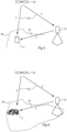
- dGPSs Differential Global Positioning Systems, dGPSs, enhance the positioning data of GPS down to a few centimeters. This may be done as illustrated in fig 5 by using a fixed station 31, located at a position known with high precision.
- Both the mobile device 11 and the fixed station 31 receive 35 satellite timing data from a plurality of satellites 33.
- This correction data C which when combined with the position determined based on the satellite reception renders the known position, is transmitted 37 to the mobile device 11. Based on the received satellite data P and the correction data C, the mobile device 11 may determine its position with higher precision.
- an RTK Real Time Kinematics
- RTK produces a correction signal based on the phase of the received satellite signal carrier wave.
- the system may in addition to the lawnmower itself include a local RTK reference station as the fixed station 31.
- this fixed station is located at a well known position in a global coordinate system such as WGS84, although this is not necessary as will be discussed.
- WGS84 global coordinate system
- the mobile device 11 receives 35 satellite data P from a plurality of satellites 33, while also receiving 37 correction data C from the fixed station 31.
- the mobile device's 11 position is determined with higher precision, and as a result the positions of the work area 30, which is being built up by the user in the user interface of the mobile device, are defined with higher precision too.
- the corresponding position data is sent to the robotic lawnmower which can process the defined work area 30 while determining its position in relation to the defined work area 30. This may, as illustrated in fig 6 , be done by receiving 37 correction data C from the same fixed station 31. This concept has some advantages.
- the mobile device 11 as well as the robotic lawnmower 1 will operate within a short distance from the fixed station 31, typically less than 100 m.
- This provides correction data with high quality compared to a more distant fixed station which may experience slightly different signal propagation conditions, for instance, leading to different correction data.
- the communication of the correction data can be arranged as a local point-to-point link for instance using UHF radio or even Bluetooth or WLAN, for instance.
- the robotic lawnmower 1 and the mobile device 11 receive data from the same fixed station 31, the exact positioning of that fixed station 31 is not critical. Even if the position of the fixed station 31 is determined with some offset with regard to a global coordinate system such as WGS84, this offset will be the same in work area 30 as defined with the mobile device 11 and as used by the robotic lawnmower 1. Thereby the robotic lawnmower 1 will nevertheless operate as intended when the work area 30 was defined.
- the fixed station 31 may be integrated in a lawnmower charging station, for instance.
- networks of fixed stations that transmit correction data for instance using the format RTCM SC-104, which may be accessed by the mobile device 11. Such data may be sent via a cellular mobile system or via Internet.
- correction data from fixed stations interpolated data from several fixed station may be accomplished.
- the separate, mobile device may receive the combination of satellite positioning data and correction positioning data from a reference station in different ways as follows. It should be noted that the robotic lawnmower may receive data in the same way, or differently.
- RTK real-time kinematic correction
- determining the GPS (more generally GNSS) errors by evaluating satellite signals in one or more fixed reference stations.
- the determined errors may then be distributed for instance using IP communication, although as mentioned other communication means are conceivable.
- This correction data loses accuracy with increasing distance from the reference station but is generally useful even at several km therefrom.
- accuracy in the cm range may be obtained in less than a half minute.
- a notification 45 may be presented in the user interface when the higher precision position detection is achieved. This prompts the user to begin registering for instance boundary positions 47 of the intended work area.
Landscapes
- Engineering & Computer Science (AREA)
- Aviation & Aerospace Engineering (AREA)
- Radar, Positioning & Navigation (AREA)
- Remote Sensing (AREA)
- Physics & Mathematics (AREA)
- General Physics & Mathematics (AREA)
- Automation & Control Theory (AREA)
- Life Sciences & Earth Sciences (AREA)
- Environmental Sciences (AREA)
- Position Fixing By Use Of Radio Waves (AREA)
Applications Claiming Priority (2)
| Application Number | Priority Date | Filing Date | Title |
|---|---|---|---|
| SE2351480A SE2351480A1 (en) | 2023-12-21 | 2023-12-21 | Robotic lawnmower system |
| EP24164029.1A EP4575693A1 (fr) | 2023-12-21 | 2024-03-18 | Système de tondeuse à gazon robotisée |
Publications (1)
| Publication Number | Publication Date |
|---|---|
| EP4575694A1 true EP4575694A1 (fr) | 2025-06-25 |
Family
ID=93744117
Family Applications (1)
| Application Number | Title | Priority Date | Filing Date |
|---|---|---|---|
| EP24218656.7A Pending EP4575694A1 (fr) | 2023-12-21 | 2024-12-10 | Système de tondeuse à gazon robotisée |
Country Status (1)
| Country | Link |
|---|---|
| EP (1) | EP4575694A1 (fr) |
Citations (4)
| Publication number | Priority date | Publication date | Assignee | Title |
|---|---|---|---|---|
| US20030144774A1 (en) * | 2002-01-29 | 2003-07-31 | Trissel Ronald L. | Kit and method for converting conventional lawnmower to a robotic lawnmower |
| US20190049593A1 (en) * | 2016-04-13 | 2019-02-14 | Positec Power Tools (Suzhou) Co., Ltd. | Differential Global Positioning System and Positioning Method Thereof |
| EP3767420A1 (fr) | 2019-07-15 | 2021-01-20 | Deere & Company | Système de détection de limite de tondeuse robotique |
| US20230004172A1 (en) * | 2016-04-12 | 2023-01-05 | Positec Power Tools (Suzhou) Co., Ltd. | Automatic Working System, Self-Moving Device, and Methods for Controlling Same |
-
2024
- 2024-12-10 EP EP24218656.7A patent/EP4575694A1/fr active Pending
Patent Citations (4)
| Publication number | Priority date | Publication date | Assignee | Title |
|---|---|---|---|---|
| US20030144774A1 (en) * | 2002-01-29 | 2003-07-31 | Trissel Ronald L. | Kit and method for converting conventional lawnmower to a robotic lawnmower |
| US20230004172A1 (en) * | 2016-04-12 | 2023-01-05 | Positec Power Tools (Suzhou) Co., Ltd. | Automatic Working System, Self-Moving Device, and Methods for Controlling Same |
| US20190049593A1 (en) * | 2016-04-13 | 2019-02-14 | Positec Power Tools (Suzhou) Co., Ltd. | Differential Global Positioning System and Positioning Method Thereof |
| EP3767420A1 (fr) | 2019-07-15 | 2021-01-20 | Deere & Company | Système de détection de limite de tondeuse robotique |
Non-Patent Citations (1)
| Title |
|---|
| BLESING CHRISTIAN ET AL: "Accuracy Evaluation of a Low-Cost Differential Global Positioning System for Mobile Robotics", 2023 IEEE SENSORS, IEEE, 29 October 2023 (2023-10-29), pages 1 - 4, XP034477580, DOI: 10.1109/SENSORS56945.2023.10324934 * |
Similar Documents
| Publication | Publication Date | Title |
|---|---|---|
| US12554262B2 (en) | 3-D image system for vehicle control | |
| US11758839B2 (en) | Method for teaching at least one section of a delimiting border of a land area for a green area maintenance system, method for operating a green area maintenance system, teach-in system and green area maintenance system | |
| EP3627269A1 (fr) | Procédé et appareil de suivi de cible, dispositif mobile et support de stockage | |
| EP2288870B1 (fr) | Procédés utilisant des données de position/attitude pour améliorer un système de guidage de véhicule | |
| US11029707B2 (en) | Moving object, moving object control method, moving object control system, and moving object control program | |
| KR101469077B1 (ko) | 현지조사자료를 활용한 수치지도 업데이트 시스템 | |
| US11869159B2 (en) | High density 3D environment capture with guided mixed reality | |
| WO2018128669A1 (fr) | Systèmes et procédés d'utilisation d'une fenêtre glissante d'époques de localisation gps en odométrie visuelle-inertielle | |
| CN109974713B (zh) | 一种基于地表特征群的导航方法及系统 | |
| WO2010004911A1 (fr) | Dispositif d'assistance au déplacement de convoi de véhicules | |
| CN103477187A (zh) | 用于确定新点的测量系统和方法 | |
| CN112824937B (zh) | 一种路线生成方法、装置和割草机 | |
| JP6138326B1 (ja) | 移動体、移動体の制御方法、移動体を制御するプログラム、制御システム、及び情報処理装置 | |
| US20120158237A1 (en) | Unmanned apparatus and method of driving the same | |
| KR20120069510A (ko) | 무인 장치 및 그의 주행 방법 | |
| US11808866B2 (en) | Total station with GNSS device | |
| JP2003064725A (ja) | 無人化機械土工システム | |
| KR101193415B1 (ko) | 이미지 합성에 따른 도화 이미지 내 지형물 변형 편집을 위한 지아이에스 기반 수치지도 영상처리 시스템 및 공간영상 도화방법 | |
| US20200217665A1 (en) | Mobile platform, image capture path generation method, program, and recording medium | |
| EP4575694A1 (fr) | Système de tondeuse à gazon robotisée | |
| EP4575693A1 (fr) | Système de tondeuse à gazon robotisée | |
| CN117310756B (zh) | 多传感器融合定位方法及系统、机器可读存储介质 | |
| EP4019897B1 (fr) | Système de déplacement autonome | |
| JP4109684B2 (ja) | 移動局ナビゲーション装置 | |
| EP4557035B1 (fr) | Système de tondeuse à gazon robotisée |
Legal Events
| Date | Code | Title | Description |
|---|---|---|---|
| PUAI | Public reference made under article 153(3) epc to a published international application that has entered the european phase |
Free format text: ORIGINAL CODE: 0009012 |
|
| STAA | Information on the status of an ep patent application or granted ep patent |
Free format text: STATUS: REQUEST FOR EXAMINATION WAS MADE |
|
| 17P | Request for examination filed |
Effective date: 20241210 |
|
| AK | Designated contracting states |
Kind code of ref document: A1 Designated state(s): AL AT BE BG CH CY CZ DE DK EE ES FI FR GB GR HR HU IE IS IT LI LT LU LV MC ME MK MT NL NO PL PT RO RS SE SI SK SM TR |
|
| STAA | Information on the status of an ep patent application or granted ep patent |
Free format text: STATUS: EXAMINATION IS IN PROGRESS |
|
| 17Q | First examination report despatched |
Effective date: 20260122 |