EP4575752A2 - Étiquette électronique pour rayon avec déclenchement d'action - Google Patents
Étiquette électronique pour rayon avec déclenchement d'action Download PDFInfo
- Publication number
- EP4575752A2 EP4575752A2 EP25172549.5A EP25172549A EP4575752A2 EP 4575752 A2 EP4575752 A2 EP 4575752A2 EP 25172549 A EP25172549 A EP 25172549A EP 4575752 A2 EP4575752 A2 EP 4575752A2
- Authority
- EP
- European Patent Office
- Prior art keywords
- shelf label
- shelf
- image content
- designed
- nfc
- Prior art date
- Legal status (The legal status is an assumption and is not a legal conclusion. Google has not performed a legal analysis and makes no representation as to the accuracy of the status listed.)
- Pending
Links
Images


Classifications
-
- G—PHYSICS
- G09—EDUCATION; CRYPTOGRAPHY; DISPLAY; ADVERTISING; SEALS
- G09G—ARRANGEMENTS OR CIRCUITS FOR CONTROL OF INDICATING DEVICES USING STATIC MEANS TO PRESENT VARIABLE INFORMATION
- G09G3/00—Control arrangements or circuits, of interest only in connection with visual indicators other than cathode-ray tubes
- G09G3/20—Control arrangements or circuits, of interest only in connection with visual indicators other than cathode-ray tubes for presentation of an assembly of a number of characters, e.g. a page, by composing the assembly by combination of individual elements arranged in a matrix no fixed position being assigned to or needed to be assigned to the individual characters or partial characters
- G09G3/2092—Details of a display terminals using a flat panel, the details relating to the control arrangement of the display terminal and to the interfaces thereto
- G09G3/2096—Details of the interface to the display terminal specific for a flat panel
-
- G—PHYSICS
- G06—COMPUTING OR CALCULATING; COUNTING
- G06F—ELECTRIC DIGITAL DATA PROCESSING
- G06F3/00—Input arrangements for transferring data to be processed into a form capable of being handled by the computer; Output arrangements for transferring data from processing unit to output unit, e.g. interface arrangements
- G06F3/14—Digital output to display device ; Cooperation and interconnection of the display device with other functional units
- G06F3/147—Digital output to display device ; Cooperation and interconnection of the display device with other functional units using display panels
-
- G—PHYSICS
- G01—MEASURING; TESTING
- G01C—MEASURING DISTANCES, LEVELS OR BEARINGS; SURVEYING; NAVIGATION; GYROSCOPIC INSTRUMENTS; PHOTOGRAMMETRY OR VIDEOGRAMMETRY
- G01C9/00—Measuring inclination, e.g. by clinometers, by levels
-
- G—PHYSICS
- G01—MEASURING; TESTING
- G01J—MEASUREMENT OF INTENSITY, VELOCITY, SPECTRAL CONTENT, POLARISATION, PHASE OR PULSE CHARACTERISTICS OF INFRARED, VISIBLE OR ULTRAVIOLET LIGHT; COLORIMETRY; RADIATION PYROMETRY
- G01J1/00—Photometry, e.g. photographic exposure meter
- G01J1/42—Photometry, e.g. photographic exposure meter using electric radiation detectors
- G01J1/44—Electric circuits
-
- G—PHYSICS
- G01—MEASURING; TESTING
- G01S—RADIO DIRECTION-FINDING; RADIO NAVIGATION; DETERMINING DISTANCE OR VELOCITY BY USE OF RADIO WAVES; LOCATING OR PRESENCE-DETECTING BY USE OF THE REFLECTION OR RERADIATION OF RADIO WAVES; ANALOGOUS ARRANGEMENTS USING OTHER WAVES
- G01S13/00—Systems using the reflection or reradiation of radio waves, e.g. radar systems; Analogous systems using reflection or reradiation of waves whose nature or wavelength is irrelevant or unspecified
- G01S13/02—Systems using reflection of radio waves, e.g. primary radar systems; Analogous systems
- G01S13/06—Systems determining position data of a target
- G01S13/08—Systems for measuring distance only
-
- G—PHYSICS
- G09—EDUCATION; CRYPTOGRAPHY; DISPLAY; ADVERTISING; SEALS
- G09F—DISPLAYING; ADVERTISING; SIGNS; LABELS OR NAME-PLATES; SEALS
- G09F3/00—Labels, tag tickets, or similar identification or indication means; Seals; Postage or like stamps
- G09F3/08—Fastening or securing by means not forming part of the material of the label itself
- G09F3/18—Casings, frames or enclosures for labels
- G09F3/20—Casings, frames or enclosures for labels for adjustable, removable, or interchangeable labels
- G09F3/204—Casings, frames or enclosures for labels for adjustable, removable, or interchangeable labels specially adapted to be attached to a shelf or the like
-
- G—PHYSICS
- G01—MEASURING; TESTING
- G01J—MEASUREMENT OF INTENSITY, VELOCITY, SPECTRAL CONTENT, POLARISATION, PHASE OR PULSE CHARACTERISTICS OF INFRARED, VISIBLE OR ULTRAVIOLET LIGHT; COLORIMETRY; RADIATION PYROMETRY
- G01J1/00—Photometry, e.g. photographic exposure meter
- G01J1/02—Details
- G01J1/0219—Electrical interface; User interface
-
- G—PHYSICS
- G01—MEASURING; TESTING
- G01J—MEASUREMENT OF INTENSITY, VELOCITY, SPECTRAL CONTENT, POLARISATION, PHASE OR PULSE CHARACTERISTICS OF INFRARED, VISIBLE OR ULTRAVIOLET LIGHT; COLORIMETRY; RADIATION PYROMETRY
- G01J1/00—Photometry, e.g. photographic exposure meter
- G01J1/02—Details
- G01J1/0247—Details using a charging unit
-
- G—PHYSICS
- G01—MEASURING; TESTING
- G01J—MEASUREMENT OF INTENSITY, VELOCITY, SPECTRAL CONTENT, POLARISATION, PHASE OR PULSE CHARACTERISTICS OF INFRARED, VISIBLE OR ULTRAVIOLET LIGHT; COLORIMETRY; RADIATION PYROMETRY
- G01J1/00—Photometry, e.g. photographic exposure meter
- G01J1/42—Photometry, e.g. photographic exposure meter using electric radiation detectors
- G01J1/4204—Photometry, e.g. photographic exposure meter using electric radiation detectors with determination of ambient light
-
- G—PHYSICS
- G01—MEASURING; TESTING
- G01J—MEASUREMENT OF INTENSITY, VELOCITY, SPECTRAL CONTENT, POLARISATION, PHASE OR PULSE CHARACTERISTICS OF INFRARED, VISIBLE OR ULTRAVIOLET LIGHT; COLORIMETRY; RADIATION PYROMETRY
- G01J1/00—Photometry, e.g. photographic exposure meter
- G01J1/42—Photometry, e.g. photographic exposure meter using electric radiation detectors
- G01J1/44—Electric circuits
- G01J2001/4446—Type of detector
- G01J2001/446—Photodiode
-
- G—PHYSICS
- G01—MEASURING; TESTING
- G01S—RADIO DIRECTION-FINDING; RADIO NAVIGATION; DETERMINING DISTANCE OR VELOCITY BY USE OF RADIO WAVES; LOCATING OR PRESENCE-DETECTING BY USE OF THE REFLECTION OR RERADIATION OF RADIO WAVES; ANALOGOUS ARRANGEMENTS USING OTHER WAVES
- G01S13/00—Systems using the reflection or reradiation of radio waves, e.g. radar systems; Analogous systems using reflection or reradiation of waves whose nature or wavelength is irrelevant or unspecified
- G01S13/88—Radar or analogous systems specially adapted for specific applications
-
- G—PHYSICS
- G09—EDUCATION; CRYPTOGRAPHY; DISPLAY; ADVERTISING; SEALS
- G09F—DISPLAYING; ADVERTISING; SIGNS; LABELS OR NAME-PLATES; SEALS
- G09F3/00—Labels, tag tickets, or similar identification or indication means; Seals; Postage or like stamps
- G09F3/08—Fastening or securing by means not forming part of the material of the label itself
- G09F3/18—Casings, frames or enclosures for labels
- G09F3/20—Casings, frames or enclosures for labels for adjustable, removable, or interchangeable labels
- G09F3/208—Electronic labels, Labels integrating electronic displays
-
- G—PHYSICS
- G09—EDUCATION; CRYPTOGRAPHY; DISPLAY; ADVERTISING; SEALS
- G09G—ARRANGEMENTS OR CIRCUITS FOR CONTROL OF INDICATING DEVICES USING STATIC MEANS TO PRESENT VARIABLE INFORMATION
- G09G2330/00—Aspects of power supply; Aspects of display protection and defect management
- G09G2330/02—Details of power systems and of start or stop of display operation
- G09G2330/021—Power management, e.g. power saving
- G09G2330/023—Power management, e.g. power saving using energy recovery or conservation
-
- G—PHYSICS
- G09—EDUCATION; CRYPTOGRAPHY; DISPLAY; ADVERTISING; SEALS
- G09G—ARRANGEMENTS OR CIRCUITS FOR CONTROL OF INDICATING DEVICES USING STATIC MEANS TO PRESENT VARIABLE INFORMATION
- G09G2356/00—Detection of the display position w.r.t. other display screens
-
- G—PHYSICS
- G09—EDUCATION; CRYPTOGRAPHY; DISPLAY; ADVERTISING; SEALS
- G09G—ARRANGEMENTS OR CIRCUITS FOR CONTROL OF INDICATING DEVICES USING STATIC MEANS TO PRESENT VARIABLE INFORMATION
- G09G2370/00—Aspects of data communication
- G09G2370/16—Use of wireless transmission of display information
-
- G—PHYSICS
- G09—EDUCATION; CRYPTOGRAPHY; DISPLAY; ADVERTISING; SEALS
- G09G—ARRANGEMENTS OR CIRCUITS FOR CONTROL OF INDICATING DEVICES USING STATIC MEANS TO PRESENT VARIABLE INFORMATION
- G09G2380/00—Specific applications
- G09G2380/04—Electronic labels
-
- G—PHYSICS
- G09—EDUCATION; CRYPTOGRAPHY; DISPLAY; ADVERTISING; SEALS
- G09G—ARRANGEMENTS OR CIRCUITS FOR CONTROL OF INDICATING DEVICES USING STATIC MEANS TO PRESENT VARIABLE INFORMATION
- G09G3/00—Control arrangements or circuits, of interest only in connection with visual indicators other than cathode-ray tubes
- G09G3/20—Control arrangements or circuits, of interest only in connection with visual indicators other than cathode-ray tubes for presentation of an assembly of a number of characters, e.g. a page, by composing the assembly by combination of individual elements arranged in a matrix no fixed position being assigned to or needed to be assigned to the individual characters or partial characters
- G09G3/34—Control arrangements or circuits, of interest only in connection with visual indicators other than cathode-ray tubes for presentation of an assembly of a number of characters, e.g. a page, by composing the assembly by combination of individual elements arranged in a matrix no fixed position being assigned to or needed to be assigned to the individual characters or partial characters by control of light from an independent source
- G09G3/3433—Control arrangements or circuits, of interest only in connection with visual indicators other than cathode-ray tubes for presentation of an assembly of a number of characters, e.g. a page, by composing the assembly by combination of individual elements arranged in a matrix no fixed position being assigned to or needed to be assigned to the individual characters or partial characters by control of light from an independent source using light modulating elements actuated by an electric field and being other than liquid crystal devices and electrochromic devices
- G09G3/344—Control arrangements or circuits, of interest only in connection with visual indicators other than cathode-ray tubes for presentation of an assembly of a number of characters, e.g. a page, by composing the assembly by combination of individual elements arranged in a matrix no fixed position being assigned to or needed to be assigned to the individual characters or partial characters by control of light from an independent source using light modulating elements actuated by an electric field and being other than liquid crystal devices and electrochromic devices based on particles moving in a fluid or in a gas, e.g. electrophoretic devices
Definitions
- the invention relates to an electronic shelf label with action triggering.
- ESL system An electronic shelf label system with action triggering for displaying information using electronic shelf label displays, hereinafter referred to as ESL system, where ESL stands for "Electronic Shelf Label", is known, for example, from the WO 2015/124197 A1
- ESL Electronic Shelf Label
- This ESL system allows for extremely energy-efficient operation of the ESLs using a proprietary time-slot communication method.
- the ESLs are mounted on shelf rails in a supermarket store, corresponding to products, and display product information.
- the ESLs' actions are triggered by a command being transmitted from a server to one of the ESLs, which results in an action in the ESL, such as changing the image content of an "electronic paper display” (EDP for short) and subsequently displaying it for a relatively long period of time with essentially no energy consumption.
- EDP electronic paper display
- the invention has for its object to provide an improved shelf label and an improved shelf label system in which the above-mentioned problems are overcome.
- an electronic shelf label which has a display unit which is designed to display an image content, and a communication module which is designed for radio-based communication for the purpose of receiving image data which represent the image content and for transferring the image data to the display unit, characterized in that a detector unit is provided which is designed to detect an incorrect positioning of the electronic shelf label which deviates from a desired positioning and, upon detection of the incorrect positioning, to emit an action signal, and in that the electronic shelf label is designed to change the image content when the action signal is present.
- the object is further achieved by an electronic shelf label system which has at least one shelf label according to the invention.
- the measures according to the invention have the advantage that the shelf label can autonomously detect the presence of incorrect positioning and adapt its image content accordingly. Since the shelf label detects its incorrect positioning autonomously, i.e. independently, no server intervention or access point intervention or communication with said server or access point is necessary to detect the incorrect positioning and effect the change in the image content. Particularly preferably, the detection of the incorrect positioning and the change in the image content can also be independent of other, currently existing states of the shelf label, in particular of the electronics, i.e., can occur with high, in particular the highest, priority.
- the shelf label when configured as a shelf label display, can feature an energy-saving display unit, such as an LCD.
- an energy-saving display unit such as an LCD.
- the technology used is based on electronic ink or electronic paper technology.
- Such a display unit features a reflective screen, also known in technical jargon as an electronic paper display (EPD), and is connected to the display by means of "electronic ink.”
- Paper also called “e-paper” or “e-ink” in English.
- the black particles are placed in front of the white particles, or vice versa, in the viewing direction. This arrangement then remains in place for a relatively long time (e.g., several weeks) without further energy input.
- a relatively long time e.g., several weeks
- letters, numbers, or images with relatively high resolution can be realized to display the information in question.
- Such a reflective screen can also be realized using other technologies, known, for example, under the terms "electrowetting" or "MEMS.”
- the screen can, for example, be designed for black-and-white reproduction, grayscale reproduction, black-white-red, or even black-white-yellow reproduction. Future This includes developments that enable full-color or multi-color display.
- Such a screen is generally a reflective, i.e., passive, non-self-illuminating screen, in which the relatively static information display is based on the light generated by an external (artificial or natural) light source shining onto the screen and being reflected from there to the viewer.
- the target positioning can, for example, be understood as an attachment to a shelf rail, with the back of the shelf label usually lying flat against the shelf rail.
- Shelf labels attached in this way can have a horizontal or slightly upward orientation of the screen of their display unit.
- the housings of the shelf labels are usually cubic in design, so that the orientation of the screen is usually automatically determined by the orientation of the shelf rail. Less commonly, the screens are oriented slightly downwards, which only seems sensible if they are positioned above the head of a person or viewer.
- shelf labels can also be designed for placement on tables or shelves, from which their target positioning is essentially determined by the usually slight upward inclination of the screen, which is optimized for viewing their image content.
- each shelf label has its own personal, individual target positioning, although a group of shelf labels can of course also have a substantially similar or even identical target positioning, e.g. if they are attached to identically designed shelf rails.
- Incorrect positioning is understood to mean a positioning that deviates from the individual target positioning, which can essentially be detected by recording a physical parameter that is typical for the target positioning or for the incorrect positioning, which is discussed in detail below.
- the detector unit can have a photodiode connected to detector electronics. With the help of the photodiode, it is easy to determine whether the shelf label has been removed, for example, from a shelf rail or from a shelf base.
- the photodiode is preferably installed in the housing of the shelf label in such a way that its light-sensitive zone can receive ambient light from the shelf label when the shelf label has been removed from the shelf rail (i.e., from the desired position) or lifted from the shelf base or table (i.e., from the desired position).
- the light-emitting diode is therefore installed in such a way that its light-sensitive zone can receive light falling on the rear wall of the shelf label housing.
- the LED is therefore installed in such a way that its light-sensitive zone can receive light falling on the bottom wall of the shelf label housing. This is always the case when the shelf label has been lifted from the shelf or table, so the light falls on the floor wall where the control label would otherwise be located.
- the detector electronics are designed to detect differences in the photodiode's conductivity and, depending on a preset threshold, determine a detection. It can also be provided that the photodiode is not completely shaded when the target positioning is assumed.
- the detector unit can have a proximity sensor connected to the detector electronics. Similar to the example discussed with regard to the photodiode, the proximity sensor can also be used or integrated into the shelf label housing.
- the physical principle according to which the proximity sensor operates essentially consists in emitting an electromagnetic field or signal, and the detector electronics are designed to detect a change in the signal reflected by another object in order to detect an incorrect positioning deviating from the target position.
- the use of the proximity sensor is particularly suitable when, for example, a distance already exists in the target position between the respective shelf label and a reference object to which the electromagnetic field or signal is emitted.
- the detector unit can comprise a tilt or inclination sensor connected to the detector electronics.
- Inclination sensors are also referred to as “inclinometers” or “clinometers” and essentially measure an angle of an object relative to the direction of gravity. In the present application of the tilt sensor, however, this angle does not need to be determined absolutely. Rather, it is entirely sufficient for the detector electronics to be configured to detect a change in this angle, which is typically the case when a shelf label is removed from a shelf rail (target positioning) (e.g., falls off it) and then remains on the floor, e.g., with the screen facing down or up (incorrect positioning), or is moved from an upright orientation (target positioning) to a horizontal position (incorrect positioning) on a shelf or table.
- target positioning e.g., falls off it
- the detector unit can include a time-of-flight sensor connected to the detector electronics.
- a time-of-flight sensor is based on the principle that the distance to another object is measured based on the time difference between the emission of a signal and the reception of the signal reflected by another object.
- Time-of-flight sensors are typically quite complex, but their use in the present context opens up further possibilities.
- the time-of-flight sensor can be used to easily determine whether or not there is a deviation from the target positioning. If such a time-of-flight sensor is provided on the back of a shelf label designed for shelf rail mounting, it would essentially detect no distance between the shelf label and the shelf rail when the shelf label is positioned as desired on the shelf rail.
- the time-of-flight sensor can be used to determine the distance to the nearest object. This is usually the underside of a shelf above the shelf label if the shelf label is still on a shelf within the shelf, or the ceiling of a store if the shelf label is on the floor of the store or on the top shelf of a shelf with a clear view of the ceiling, or the underside of a device or shelf if the shelf label is placed below the device or shelf. Based on the distance measurement, which does not even have to be absolute but only needs to be relative, because the scenarios discussed lead to sufficiently distinguishable sensor values, a conclusion can be drawn about the expected location of the shelf label, which can make it easier to find the shelf label again.
- the status of the detector unit as well as the sensor values can of course also be queried.
- the shelf label comprises a long-term energy storage device for electrically supplying the display unit during its image content change activity.
- this long-term energy storage device may be a battery, a rechargeable battery, a It can be a rechargeable battery or a so-called "supercapacitor,” or supercap for short.
- This long-term energy storage ensures that the display unit can perform a screen change activity at any time.
- the advantage of the aforementioned supercapacitor lies in the following fact:
- a supercapacitor, also called an ultracapacitor is a high-performance capacitor with a capacitance value that is much higher than other capacitors, but has lower voltage limits, bridging the gap between electrolytic capacitors and rechargeable batteries. It typically stores 10 to 100 times more energy per unit volume or mass than electrolytic capacitors, can absorb and release charges much faster than batteries, and tolerates many more charge and discharge cycles than rechargeable batteries.
- the long-term energy storage device can be implemented, for example, as a supercapacitor, in addition to a battery intended for normal operation.
- the shelf label can also include an energy transfer receiver that can receive energy contactlessly using directed radio signals emitted by an energy transfer transmitter to charge the long-term energy storage device. This energy transfer technology is known as "Power over WiFi.”
- the communication module can, for example, be configured to communicate with an access point using Wi-Fi, ZigBee, or Bluetooth communication protocols, etc.
- the access point forms an interface to a server that runs inventory management or shelf label control software.
- this software can also be provided as a cloud solution via an external data center.
- a store can have multiple such access points installed, with each access point supplying a group of shelf labels that are wirelessly assigned to it, i.e., registered with it.
- the communication module is designed for radio-based communication according to a time slot communication method, wherein in the time slot communication method a number of time slots per time slot cycle are available for communication in a repeating sequence, preferably each time slot is identified by a unique time slot symbol, and the communication module has an energy-saving sleep state in which there is no readiness for communication, and the communication module has an active state in which there is readiness for communication, and wherein the communication module is designed to switch from the sleep state to the active state in a timely manner with the occurrence of the time slot to which the shelf label is assigned, and wherein the long-term energy storage device is used to supply electricity to the detector unit during the active and sleep states.
- This design has the advantage that a large part of the electronics of the shelf label can remain in the energy-saving sleep state for as long as possible, while at the same time the detector unit can be active in order to detect the change in the positioning of the shelf label as quickly as possible after the change in positioning occurs.
- the electronics of the display unit can thus be permanently supplied with energy, even if there is no detection of incorrect positioning.
- the electronics of the display unit can only be supplied with energy when incorrect positioning is detected. This can be controlled, for example, by the detector unit. After the image content change activity has been completed, the electrical supply to the display unit can be switched back on.
- the preferred method for communication is a proprietary time slot communication method, which in principle consists of WO2015/124197 , pages 2 to 4, as well as Figures 1-8C with associated description, the specific disclosure of which is hereby incorporated by reference, is used, the most essential aspects of which are discussed below.
- the access point communicates with a number of shelf labels in such a way that, in a continuously repeating sequence, a number of time slots are available for communication per time slot cycle. Each time slot is uniquely identified by a unique time slot symbol and can thus be distinguished from other time slots solely by the time slot symbol.
- the access point transmits a synchronization data signal for the currently available time slot, comprising the time slot symbol at the beginning of the respective time slot.
- Shelf labels are familiar with this system of the time slot communication method and are designed to switch from an (extremely energy-saving) sleep state, in which, for example, there is no readiness to receive a radio signal, to an active state, in which, for example, there is readiness to receive a radio signal, at a wake-up time and to receive the synchronization data signal in the active state and, if the received time slot symbol indicates a time slot specific to the respective shelf label, to define a new wake-up time corresponding to the next occurrence of the time slot specific to this shelf label in a time slot cycle following the currently existing time slot cycle.
- the synchronization data signal could be formed exclusively by the time slot symbol, and other communication parameters required for communication with the access point (or server), such as address data for addressing or command data for transmitting commands, could be separated from the synchronization data signal.
- the time slot symbol is preferably an extremely compact indicator for synchronizing communication within the system, i.e., it can be formed, for example, by the consecutive number of the time slot, it is advisable to embed additional information into the synchronization data signal in addition to the time slot symbol.
- the access point is designed to embed address data into the synchronization data signal, with the aid of which a number of shelf labels can be individually addressed per time slot.
- the shelf label could also perform a standardized (predefined) task simply by recognizing its individual address, without having to receive an explicit command.
- address data for addressing an individual shelf label and command data for transmitting a command to this individual shelf label are transmitted, and the shelf label is configured to evaluate the command data and execute the command when it is individually addressed using the address data. This allows a command to be transmitted for a single shelf label in a sometimes relatively large group of shelf labels.
- the access point can also be designed in such a way that it only tunnels data originating from the server or the shelf label, i.e. only implements the conversion between wired communication and radio communication, whereby the time slot communication process is then provided or handled directly by the server.
- the EPD does not require any energy consumption over an extended period of time to display image content. Therefore, in conventional shelf labels, the EPD is often only supplied with electrical energy within a time slot assigned to the shelf label when a change in the image content is necessary due to communication via the communication module in the active state.
- the long-term energy storage is now also used during the sleep state — which usually lasts relatively long compared to the active state – to supply electrical power to the display unit during its image content change activity. This allows for rapid visualization of the detected incorrect positioning, independent of the cycle of switching between the active state and the sleep state.
- the communication module is designed for communication according to a Near Field Communication, abbreviated NFC, specification and at a Receiving an NFC signal to generate a supply voltage for the shelf label, whereby the long-term energy storage is used to electrically supply the detector unit during the absence of the NFC signal, i.e. in a period without said NFC signal.
- NFC Near Field Communication
- the ESL system has a near-field communication (NFC) subsystem on a shelf rail of a shelf.
- the NFC subsystem is characterized in that the shelf rail has an NFC reader configured for radio-based communication with the access point.
- the NFC reader is now configured for radio communication with the access point according to the discussed time slot communication method.
- the NFC subsystem has a conductor loop connected to the NFC reader, which is arranged along the shelf rail and serves for NFC communication with one or more NFC-enabled shelf labels, wherein at least one NFC-enabled shelf label is attached to the shelf rail corresponding to the conductor loop.
- the NFC reader thus serves for NFC communication with the NFC-enabled shelf label, wherein the shelf labels addressed by the server are addressed or addressed via the NFC reader.
- the NFC reader used here therefore has, in addition to its standardized NFC communication module, another access communication module that is configured for communication according to the aforementioned time slot communication method.
- the NFC subsystem therefore assumes the role of a switching device in order to physically address the shelf labels addressed by the server, i.e., to be able to communicate with them.
- communication is therefore NFC-compliant, with the server addressing the shelf labels, and the NFC subsystem implementing or applying this addressing.
- Physically addressing the shelf labels can be done in two ways, as follows.
- the NFC reader stores a data structure that represents an assignment of a shelf label attached to its shelf rail to one of the time slots, wherein the NFC reader is designed to assign the time slot to which, according to the data structure, a shelf label assigned to the shelf rail, to check whether the shelf label attached to its shelf rail is addressed by the server.
- the data structure consists of the shelf label identifier, which is also known to the server and used by it for addressing, and the associated time slot symbol.
- the server does not need to be aware of the existence of the NFC reader and only needs to know the relationship between the access point and the shelf label.
- the NFC reader itself is assigned to one of the time slots and stores a data structure representing the shelf labels attached to the shelf rail of the NFC reader.
- the NFC reader is configured to check the time slot to which it is assigned to determine whether the shelf label attached to its shelf rail is addressed by the server.
- the data structure consists of the shelf label identifiers of the shelf labels attached to the shelf rail of the respective NFC reader.
- the server must also be aware of the existence of the NFC readers and the relationship between the access point and the NFC reader, as well as the relationship between the NFC readers and their shelf labels, in order to be able to address the respective shelf label indirectly via the NFC reader.
- NFC Near Field Communication
- the NFC reader generates an NFC signal and transmits it using a conductive loop (as an antenna).
- this NFC signal is first received using an NFC interface on the shelf label and used to generate an internal supply voltage to power and start the shelf label's electronics.
- the NFC interface then communicates with the NFC reader in an NFC-compliant manner via the shelf label's NFC interface.
- NFC-compliant communication uses NFC identifiers of the communication partners involved (NFC reader and NFC-enabled shelf label), which typically differ from those of the shelf label identifier.
- the NFC-enabled shelf label is further designed in such a way that it stores the electrical energy transmitted by the NFC signal from the NFC reader in a supercap for its operation during the absence of the NFC signal. This enables autonomous provision of various functions, in particular the detection of incorrect positioning and image content change activity, independent of the period of the NFC signal.
- the NFC reader can also have a battery and/or accumulator-based power supply.
- the NFC reader preferably has a supercapacitor and a power transfer receiver, which, as discussed above, enables "Power-over-WiFi" power transfer, so that the NFC reader of each shelf rail is supplied with power in a contactless manner.
- the NFC reader is further configured to use the radio signal used to transfer the power to electrically charge the supercapacitor.
- the long-term energy storage device is used to power the display unit during its image content change activity in the absence of the NFC signal.
- the immediate availability of the power supply allows the display unit to visually represent the incorrect positioning without delay and, above all, independently of the NFC signal-based power supply.
- the shelf label for changing the image content is designed such that the display unit is designed to directly receive the action signal, in particular as an interrupt signal, and, as a result of receiving the action signal, is designed to delete the last displayed image content.
- This measure represents the most effective approach to immediately avoid misunderstandings or confusion when incorrect positioning is detected.
- a deleted screen i.e. a screen that displays no content, cannot give a customer the wrong impression and is usually ignored.
- the supermarket staff only needs to be instructed to collect shelf labels that they find in unusual positions or with unusual orientation and that display no image content.
- the configuration for changing the image content can include the measure that causes the display unit to display a message as image content instead of the last displayed image content, which reflects the internal state of the detection, particularly in combination with a call to action.
- This measure is based on the fact that an "X" filling the screen, along with the text "Hand over label,” is stored in an internal memory of the display unit as image content.
- the "X” here represents the internal state of the detection of incorrect positioning, and the text "Hand over label” in this context forms the call to action, which is directed at both staff and customers in a user-group-neutral manner.
- the shelf label in particular its detector unit, is designed to digitally store the detection status of the incorrect positioning. This prevents multiple changes in positioning from leading to multiple image content change activities, which would ultimately result in unnecessary energy consumption.
- the shelf label it has also proven advantageous for the shelf label to be designed to only perform an image content change activity again after the change in the image content occurred due to the detection of the incorrect positioning, after the stored state of the detection of the incorrect positioning has been deleted with the help of communication via the communication module.
- This can be implemented in such a way that a status bit is stored in the memory of the display unit, which represents the incorrect positioning and the status bit must first be changed (e.g. deleted) by the server. This ensures that a shelf label is excluded from regular use until the server has registered the incorrect positioning and the shelf label has been regularly integrated into the ESL system again.
- the server could detect the incorrect positioning by communicating via the communication module (i.e., query the status bit), delete the stored state (i.e., change the value of the status bit), and then reassign the shelf label to a product (or reactivate this previous assignment).
- the electronics of the various system devices, as well as their interfaces, etc., can be implemented using a wide variety of passive and active electronic components, both discretely and in integrated form.
- a microprocessor with corresponding peripheral components or a microcontroller is preferably used, with software executing the various functionalities. So-called ASICs (Application-Specific Integrated Circuits) can also be used.
- the various components or functional groups, particularly the loads in the shelf label can contain the aforementioned individual integrated circuits (microcontrollers, microprocessors, ASICs, function-specific ICs, etc.) in addition to passive components.
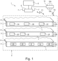
- a shelf label system 1 which comprises a number of identically designed electronic NFC-enabled shelf labels 2A-2K realized as shelf label displays, which are attached to three "intelligent" Shelf rails 3 are attached.
- Each of the shelf rails 3 has an NFC sub-system.
- Each NFC sub-system includes an NFC reader 4A-4C.
- the NFC reader 4A-4C is inserted laterally into the shelf rail 3.
- each shelf rail 3 has, as a component of the NFC sub-system, a conductor loop L that extends along the entire length of the shelf rail 3 and whose conductor loop connections C are electrically connected to the NFC reader 4A-4C.
- the conductor loop L forms the antenna of the respective NFC reader 4A-4C and is thus a component of the respective NFC reader 4A-4C that is integrated into the shelf rail 3.
- shelf labels 2A-2K are installed on the respective shelf rail 3 corresponding to its conductor loop L and have been detected by the NFC reader 4A-4C there, these shelf labels 2A-2K also form part of the respective NFC sub-system of the shelf rail 3.
- the respective NFC reader 4A-4C acts as a shelf rail controller for controlling the shelf labels 2A-2K installed on its shelf rail 3.
- the respective NFC reader 4A-4C communicates contactlessly according to an NFC communication protocol with the NFC-enabled shelf labels 2A-2K installed on its shelf rail 3. To do so, it transmits an NFC signal via the conductor loop L, which is used by the respective shelf label 2A-2K for both power supply and data transmission.
- a data processing device which in the present case is implemented with the aid of a server 5 which is connected by cable to an access point 6 which, for example, has two antennas 7.
- the NFC readers 4A-4C are further modified such that they are in radio contact with the access point 6 via first radio signals F1 according to a proprietary time slot communication method. This allows, for example, the image content of the shelf labels 2A-2K to be changed from the server 5 and, if necessary, the associated status information from the shelf labels 2A-2K can be retrieved and transmitted to the server 5.
- Each of the shelf rails 3 is mounted on an individual shelf 8 at its front edge.
- the three illustrated shelves 8 all belong to a shelf 9 that is only indicated very schematically.
- Various products can be presented on the shelves 8, which, however, are not shown in this case for the sake of simplicity.
- the NFC readers 4A-4C are configured such that they can themselves be supplied with energy using a second radio signal F2.
- the system 1 comprises a supply transmitter 10 (also referred to as a radio energy source) configured to transmit electrical energy to a receiver (i.e., to one of the NFC readers 4A-4C) using a focused or directed (second) radio signal F2 with a specific transmission power, such as 5 W.
- a supply transmitter 10 also comprises a plurality of antennas 10A (six are shown here), with the aid of which the direction of energy transmission (ultimately the propagation of the second radio signal F2) can be adjusted relatively precisely, so that the energy-transmitting second radio signal F2 arrives precisely at the respective NFC reader 4A-4C.
- This energy transmission is known under the term "Power over WiFi.”
- shelf labels 2A-2K based on the Figure 2 discussed. Since it is assumed in the present case that all shelf labels 2A - 2K are identical, reference is made below only to a single shelf label 2A.
- the block diagram shows a communication module of the shelf label 2A, designed as the first NFC interface 11, with a coil 12A, which is connected to an interface circuit 11A.
- the coil 12A together with an interface capacitor 12B, forms an antenna resonant circuit 12C, with the aid of which an NFC signal from an NFC-enabled device can be received.
- the NFC-enabled device is the NFC reader 4A-4C.
- the coil 12A is installed in the shelf label 2A as close as possible to the rear wall of the housing, essentially parallel to the rear wall of the housing.
- the antenna resonant circuit 12C can be used to receive the signal generated by the conducting loop L.
- the NFC signal emitted is received and used in the shelf label 2A for power supply as well as for bidirectional communication of data with the respective NFC readers 4A-4C.
- the shelf label 2A has a so-called contactless power transmission unit 11B connected to the antenna resonant circuit 12C, which has a rectifier unit 11C on the input side and a voltage regulator unit 11D on the output side.
- a first supply voltage VCC1 is generated relative to a first reference potential GND1, which is then available for operating the NFC functionality as well as other system components of the shelf label 2A.
- the first NFC interface 11 further comprises a communication unit 11E, with the aid of which communication can be carried out according to the NFC specification or protocol. It comprises a load modulation unit 11F connected to the antenna resonant circuit 12C for load modulating the received NFC signal depending on the transmitted data TX. Another component is a protection unit 11G, also connected to the antenna resonant circuit 12C, which protects against undesirably high input power and is designed as a signal limiter. Furthermore, a clock generator unit 11H is connected to the antenna resonant circuit 12C and generates a system clock CLK based on the received NFC signal.
- ASK demodulation unit 11I (ASK stands for "amplitude-shift keying"), which generates received data RX from small fluctuations in the amplitude of the NFC signal rectified by the rectifier unit 11C.
- Digital data processing is performed by a microcontroller unit 11J, which is clocked by the system clock CLK and processes incoming received data RX and generates outgoing transmitted data TX.
- Data processing is performed according to a program code stored in the microcontroller unit 11J and executed by its central processing unit (CPU).
- the block diagram also shows a display unit 13A connected to the first NFC interface 11, which is divided into an electronic paper display controller 14 and an electronic paper display (EPD screen) 15 that can be controlled by the controller.
- the controller 14 interprets the received data D and, if necessary, the image content of the screen 15. changed accordingly or status information in the form of data D is transmitted via the first NFC interface 11 to the respective NFC reader 4A-4C.
- the shelf label 2A has, in addition to the display unit 13A, further consumers, namely an input unit 13E for receiving a user input, a camera unit 13D for capturing images of objects in front of the shelf label 2A, a temperature sensor unit 13C for detecting the ambient temperature of the shelf label 2A and a detector unit 13B for detecting an incorrect positioning of the electronic shelf label 2A that deviates from a target positioning, wherein upon detection of the incorrect positioning an action signal IR is emitted to the display unit 13A.
- an input unit 13E for receiving a user input
- a camera unit 13D for capturing images of objects in front of the shelf label 2A
- a temperature sensor unit 13C for detecting the ambient temperature of the shelf label 2A
- a detector unit 13B for detecting an incorrect positioning of the electronic shelf label 2A that deviates from a target positioning, wherein upon detection of the incorrect positioning an action signal IR is emitted to the display unit 13A.
- the detector unit 13B has a photodiode as a detector element, the conductivity of which changes depending on the intensity of the light that illuminates it. It is installed or integrated into the housing of the shelf label 2A in such a way that it can receive light that illuminates the back of the housing.
- the housing can have a viewing window in the center of the rear wall (see Figure 7 ), and the photodiode is mounted inside the shelf label housing on a circuit board corresponding to the viewing window.
- the photodiode can also be inserted into a recess in the rear wall of the housing and be flush with it on the outside.
- the detector unit 13B further comprises detector electronics implemented on the circuit board.
- the detector electronics comprise, for example, an operational amplifier circuit (abbreviated to OP circuit, e.g., a photodiode amplifier with a downstream comparator and, if necessary, a downstream signal conditioning circuit), which can be used to detect when the current through the photodiode exceeds a threshold.
- OP circuit e.g., a photodiode amplifier with a downstream comparator and, if necessary, a downstream signal conditioning circuit
- this can be implemented using a light sensor integrated in an IC (integrated circuit).
- the OP circuit transmits the action signal IR to the display unit 13A, specifically to an interrupt input of the display unit. 13A, which then deletes the contents of its screen 15. This can be done by replacing the currently displayed image content with another image content, i.e., in technical terms, by switching from a memory area of the display unit 13A, which stores the currently displayed, first image content in the form of data, to another memory area in which the second image content to be displayed is stored in the form of data.
- the first image content was received through communication with the server.
- the second image content which is used when deleting the screen 15, can be preset, e.g., programmed at the factory, or can be determined situation-specifically through a previous server communication.
- the process of deleting the image content is controlled by the electronic paper display controller 14, which receives the action signal IR at its interrupt input, which triggers an interrupt, which leads to the start of software stored for this situation, and which then executes this software to implement the discussed measures.
- Each of the units 13B-13E can have its own integrated controller circuit (IC), analogous to the display unit 13A.
- IC integrated controller circuit
- These additional loads 13B-13E are intended to be operated independently of the NFC signal, which, as discussed, generates the first supply voltage VCC1.
- the shelf label 2A has a long-term energy storage unit 13F, which is divided into a long-term energy storage device in the form of a supercapacitor 13H and a charging stage 13G, which is designed to charge the supercapacitor 13H.
- a charging stage 13G which is designed to charge the supercapacitor 13H.
- the charging stage 13G is connected on the input side to the first supply voltage VCC1 opposite the first reference potential GND1, i.e., to the output of the contactless power transmission unit 11B.
- the supercapacitor 13H can be connected directly to the output of the power transmission unit 11B.
- the charging stage 13G provides a second supply voltage VCC2 on the output side compared to a second reference potential GND2 where the first and second reference potentials GND1 and GND2 are identical, i.e. corresponding circuit points are connected to each other.
- the two supply voltages VCC1 and VCC2 can be different or equal in value, which ultimately depends on the specifications of the loads 13A-13E to be supplied and/or the charge state of the supercapacitor 13H.
- the display unit 13A can be supplied either only with the first supply voltage VCC1 or only with the second supply voltage VCC2, or optionally, e.g., depending on whether the first supply voltage VCC1 is present or not, either with the first supply voltage VCC1 or with the second supply voltage VCC2.
- shelf labels 2A-2K all have the same design, i.e. all those in the Figure 2 shown consumers 13A-13E, it should be clarified at this point that this does not have to be the case.
- shelf labels e.g. 2A, 2C, 2D, 2F, 2G and 2I
- Other shelf labels e.g. 2B, 2E, 2H and 2J, could have no display unit 13A at all, but instead have a camera unit and a time-of-flight sensor unit each, and finally the last remaining shelf label 2K could only have a temperature sensor unit.
- any combination of consumers 13A-13E can be provided per shelf label 2A-2K.
- all of them have at least the detector unit 13B.
- the individual availability of the respective consumer 13A-13E can be implemented by a selective hardware design of the respective consumers 13A-13E in the respective shelf label 2A-2K. This can also be realized in such a way that some or all types of consumers 13A-13E are implemented and can be enabled with the help of control commands, i.e. can be activated by software and/or are available or not available due to special designs of the housing of the respective shelf labels 2A-2K.
- shelf rail 3 has shelf labels 2G-2K, which means that it is the shelf labels shown in the Figure 1
- the shelf labels 2G-2K are positioned corresponding to the position of the conductor loop L.
- the electrical connection of the loop connections C to an electronics unit 18A of the NFC reader 4 is also visible.
- the electronics unit 18A has its own NFC reader controller (not shown), which provides the entire NFC reader functionality. With the help of the second NFC interface 18, the NFC signal can be generated and emitted, thus transmitting electrical energy to the shelf labels 2G-2K in a contactless manner and conducting bidirectional communication of data D with them.
- the conductor loop L although it is a component of the NFC reader 4, is incorporated outside the NFC reader 4 in the mechanical structure of the shelf rail 3. This is symbolized by a structure 17 of the shelf rail 3 that encloses the conductor loop L and connects to the NFC reader 4.
- the NFC reader 4 further comprises an access point communication module 19, which is used for radio-based communication with the Figure 1
- the access point 6 shown for example, is designed in the 2.4 GHz frequency band.
- the access point communication module 19 has specially designed electronics (not shown in detail) and an antenna configuration 19A, which can also comprise multiple antennas, and forms the analog interface for this radio communication.
- the supply device 4 has a control unit 20.
- the control unit 20 is implemented using a microcontroller, which is connected to the second NFC interface 18 and the access point communication module 19 via a bidirectional data bus.
- the NFC reader 4 has a power receiver 21 suitable for receiving the second radio signal F2, which with its antenna configuration 22 (which can have several antennas) and an electronics (not described in detail shown) which is designed to receive the second radio signal F2 and to store the energy transmitted thereby in an internal electrical energy storage device 23 (rechargeable battery, accumulator or supercap, etc.) and thus to generate a third supply voltage VCC3 with respect to a second reference potential GND3 for the electrical supply of the NFC reader 4.
- an internal electrical energy storage device 23 rechargeable battery, accumulator or supercap, etc.
- the control unit 20 is also connected to the supply receiver 21 via its data bus.
- the NFC reader 4 can, for example, query or monitor the charge level of the energy storage device 23 using its control unit 20. As soon as the charge level drops below a certain level, the control unit 20 can request a (re)charge, for example using the first radio signal F1. This request is received by the access point 6 and, depending on the implementation, can be forwarded directly to the supply transmitter 10 or, with the involvement of the server 5, to the supply transmitter 10. Since the exact geographical position (the three-dimensional coordinates) of each of the NFC readers 4 in the store as well as their unique reader identifier are known in system 1 (e.g., the server 5), the supply transmitter 10 can transmit the second radio signal F2 precisely directed towards the position of the respective NFC reader 4 requesting charging. There, the second radio signal F2 is received, and the energy transmitted thereby is used to charge the internal energy storage device 23.
- the control unit 20 can request a (re)charge, for example using the first radio signal F1. This request is received by the access point 6 and, depending on the implementation, can be forwarded directly to the
- the shelf rail 3 described here is therefore designed, with the aid of its NFC sub-system, for contactless communication with the shelf labels 2A-2K installed on it and an access point 6 assigned to it by radio technology, and for contactless energy provision in the sense of energy storage for the operation of the NFC reader 4 itself as well as for the contactless energy supply of the respective shelf labels 2A-2K.
- the supply transmitter 10 can also be installed in the access point 6.
- the Figure 4 a shelf rail 3 (in the Figure 1 the top shelf rail 3) with the shelf label 2C attached to it and the NFC reader 4A inserted laterally into the shelf rail 3, which is fixed with screws 24 in the structure of the shelf rail 3
- This shelf rail 3 has, for example, a length of approximately 3 m, a height of approximately 4.5 cm, and a thickness of 1.2 cm.
- the Figure 5 shows a section through the shelf rail 3 according to a Figure 4 drawn section AA, which is oriented transversely (aligned normal to the front of the shelf rail 3) through the shelf rail 3 and runs at the point at which contact elements 25 of the NFC reader 4A are formed, which serve to contact the conductor loop L of the NFC reader 4A running in the shelf rail 3.
- the contact elements 25 contact contact lugs 26, which in turn are in contact with the conductor loop connections C.
- the contact lugs 26 can be omitted if a different geometry is selected, so that the conductor loop connections C can also be contacted directly with the contact elements 25.
- a shielding plate 27 formed on the rear of the shelf rail 3 can be seen, which, analogous to the conductor loop L, also extends along the entire shelf rail 3 and allows tuning of the antenna resonant circuits of the NFC sub-system independent of environmental influences. It is also clearly visible how the back of the shelf label 2C sits flush with the shelf rail 3, so that practically no ambient light can illuminate the back of the housing of the shelf label 2C.
- the Figure 6 shows the NFC reader 4A attached to a rail or sliding mechanism, wherein the sliding mechanism is partially pulled out of a shaft of the shelf rail 3 designed to accommodate it.
- FIG. 7 shows the back of a shelf label 2A-2K, here designated by reference numeral 2, with a viewing window 28 through which light from the back of the shelf label 2 can penetrate through the viewing window 28 and illuminate a photodiode 29 attached to the circuit board of the shelf label 2 as soon as the back is no longer covered.
Landscapes
- Engineering & Computer Science (AREA)
- Physics & Mathematics (AREA)
- General Physics & Mathematics (AREA)
- Radar, Positioning & Navigation (AREA)
- Remote Sensing (AREA)
- Theoretical Computer Science (AREA)
- Spectroscopy & Molecular Physics (AREA)
- Computer Hardware Design (AREA)
- Computer Networks & Wireless Communication (AREA)
- Life Sciences & Earth Sciences (AREA)
- Sustainable Development (AREA)
- Human Computer Interaction (AREA)
- General Engineering & Computer Science (AREA)
- Display Racks (AREA)
- Cash Registers Or Receiving Machines (AREA)
- Radar Systems Or Details Thereof (AREA)
Priority Applications (1)
| Application Number | Priority Date | Filing Date | Title |
|---|---|---|---|
| EP25172549.5A EP4575752A3 (fr) | 2019-12-23 | 2019-12-23 | Étiquette électronique pour rayon avec déclenchement d'action |
Applications Claiming Priority (3)
| Application Number | Priority Date | Filing Date | Title |
|---|---|---|---|
| EP25172549.5A EP4575752A3 (fr) | 2019-12-23 | 2019-12-23 | Étiquette électronique pour rayon avec déclenchement d'action |
| PCT/EP2019/086994 WO2021129934A1 (fr) | 2019-12-23 | 2019-12-23 | Étiquette électronique de rayonnage à déclenchement d'action |
| EP19832969.0A EP4081894B1 (fr) | 2019-12-23 | 2019-12-23 | Système d'étiquette électronique pour étagère générant des actions |
Related Parent Applications (2)
| Application Number | Title | Priority Date | Filing Date |
|---|---|---|---|
| EP19832969.0A Division-Into EP4081894B1 (fr) | 2019-12-23 | 2019-12-23 | Système d'étiquette électronique pour étagère générant des actions |
| EP19832969.0A Division EP4081894B1 (fr) | 2019-12-23 | 2019-12-23 | Système d'étiquette électronique pour étagère générant des actions |
Publications (2)
| Publication Number | Publication Date |
|---|---|
| EP4575752A2 true EP4575752A2 (fr) | 2025-06-25 |
| EP4575752A3 EP4575752A3 (fr) | 2025-08-20 |
Family
ID=69147678
Family Applications (2)
| Application Number | Title | Priority Date | Filing Date |
|---|---|---|---|
| EP19832969.0A Active EP4081894B1 (fr) | 2019-12-23 | 2019-12-23 | Système d'étiquette électronique pour étagère générant des actions |
| EP25172549.5A Pending EP4575752A3 (fr) | 2019-12-23 | 2019-12-23 | Étiquette électronique pour rayon avec déclenchement d'action |
Family Applications Before (1)
| Application Number | Title | Priority Date | Filing Date |
|---|---|---|---|
| EP19832969.0A Active EP4081894B1 (fr) | 2019-12-23 | 2019-12-23 | Système d'étiquette électronique pour étagère générant des actions |
Country Status (4)
| Country | Link |
|---|---|
| US (3) | US11955052B2 (fr) |
| EP (2) | EP4081894B1 (fr) |
| CN (1) | CN114787764A (fr) |
| WO (1) | WO2021129934A1 (fr) |
Families Citing this family (4)
| Publication number | Priority date | Publication date | Assignee | Title |
|---|---|---|---|---|
| FR3099020B1 (fr) | 2019-07-15 | 2022-01-14 | Ses Imagotag | Dispositif d’imagerie pour un support d’étagère et système d’étagère comprenant le dispositif d’imagerie |
| DE202022000025U1 (de) | 2021-08-05 | 2022-01-26 | Itmediaconsult AG | Warenerkennungs- und Mengenerfassungseinheit |
| CN120693909A (zh) * | 2023-02-22 | 2025-09-23 | 高通股份有限公司 | 网络设备系统中的负载均衡 |
| US12461188B2 (en) * | 2023-09-19 | 2025-11-04 | Qualcomm Incorporated | Self-positioning of electronic shelf label (ESL) devices through inter-ESL links |
Citations (1)
| Publication number | Priority date | Publication date | Assignee | Title |
|---|---|---|---|---|
| WO2015124197A1 (fr) | 2014-02-20 | 2015-08-27 | Imagotag Gmbh | Système de communication par créneau temporel |
Family Cites Families (14)
| Publication number | Priority date | Publication date | Assignee | Title |
|---|---|---|---|---|
| US8009348B2 (en) * | 1999-05-03 | 2011-08-30 | E Ink Corporation | Machine-readable displays |
| US9818148B2 (en) * | 2013-03-05 | 2017-11-14 | Rtc Industries, Inc. | In-store item alert architecture |
| US9898712B2 (en) * | 2004-02-03 | 2018-02-20 | Rtc Industries, Inc. | Continuous display shelf edge label device |
| US20080073431A1 (en) * | 2006-09-25 | 2008-03-27 | W5 Networks, Inc. | Sensor monitoring, logging, and alerting via display enabled wireless devices for retail applications |
| GB0812770D0 (en) * | 2008-07-11 | 2008-08-20 | Zbd Displays Ltd | A display system |
| KR101062520B1 (ko) * | 2009-06-24 | 2011-09-06 | 엘지이노텍 주식회사 | 전자 가격표시기의 도난 경보장치 및 방법 |
| FI20116014A7 (fi) * | 2011-10-13 | 2013-04-14 | Mariella Labels Oy | Tiedonsiirto sähköisissä hintalappujärjestelmissä |
| CN102855516A (zh) * | 2012-07-24 | 2013-01-02 | 浙江大学 | 一种防盗电子标签 |
| EP2945115A1 (fr) * | 2014-05-16 | 2015-11-18 | Samsung Electro-Mechanics Co., Ltd. | Système électronique d'étiquette d'étagère, balise d'étiquette de rayon électronique, procédé de reconnaissance de dispositif d'affichage d'informations |
| FR3032105B1 (fr) * | 2015-01-30 | 2017-01-27 | E2V Semiconductors | Capteur radiologique avec detection de rayons x |
| CN107735808A (zh) * | 2015-05-04 | 2018-02-23 | 日升研发控股有限责任公司 | 用于控制货架显示单元并且用于在货架显示单元上图形地呈现信息的系统和方法 |
| US20190149725A1 (en) * | 2017-09-06 | 2019-05-16 | Trax Technologies Solutions Pte Ltd. | Using augmented reality for image capturing a retail unit |
| US20190180150A1 (en) * | 2017-12-13 | 2019-06-13 | Bossa Nova Robotics Ip, Inc. | Color Haar Classifier for Retail Shelf Label Detection |
| CN108960369B (zh) * | 2018-07-02 | 2022-01-25 | 京东方科技集团股份有限公司 | 电子价签、电子价签系统和更新电子价签的方法 |
-
2019
- 2019-12-23 US US17/786,648 patent/US11955052B2/en active Active
- 2019-12-23 WO PCT/EP2019/086994 patent/WO2021129934A1/fr not_active Ceased
- 2019-12-23 EP EP19832969.0A patent/EP4081894B1/fr active Active
- 2019-12-23 EP EP25172549.5A patent/EP4575752A3/fr active Pending
- 2019-12-23 CN CN201980103247.7A patent/CN114787764A/zh active Pending
-
2024
- 2024-03-08 US US18/600,420 patent/US12431063B2/en active Active
-
2025
- 2025-08-14 US US19/300,358 patent/US20250378776A1/en active Pending
Patent Citations (1)
| Publication number | Priority date | Publication date | Assignee | Title |
|---|---|---|---|---|
| WO2015124197A1 (fr) | 2014-02-20 | 2015-08-27 | Imagotag Gmbh | Système de communication par créneau temporel |
Also Published As
| Publication number | Publication date |
|---|---|
| US11955052B2 (en) | 2024-04-09 |
| US20250378776A1 (en) | 2025-12-11 |
| EP4081894B1 (fr) | 2025-06-11 |
| EP4575752A3 (fr) | 2025-08-20 |
| US12431063B2 (en) | 2025-09-30 |
| WO2021129934A1 (fr) | 2021-07-01 |
| US20230042843A1 (en) | 2023-02-09 |
| US20240257709A1 (en) | 2024-08-01 |
| EP4081894C0 (fr) | 2025-06-11 |
| CN114787764A (zh) | 2022-07-22 |
| EP4081894A1 (fr) | 2022-11-02 |
Similar Documents
| Publication | Publication Date | Title |
|---|---|---|
| EP4081894B1 (fr) | Système d'étiquette électronique pour étagère générant des actions | |
| EP4018355B1 (fr) | Système d'étiquetage électronique des étagères avec sous-système de rails d'étagères | |
| DE112014005505T5 (de) | Sensorsonde und verwandte Systeme und Verfahren | |
| WO2022188956A1 (fr) | Système de bus et dispositif de support comprenant un tel système de bus | |
| EP3984259B1 (fr) | Système d'étiquetage électronique des étagères avec sous-système de rails d'étagères | |
| EP4081893A1 (fr) | Système d'étiquettes électroniques de rayonnage comprenant une alimentation électrique qui assure un fonctionnement longue durée de consommateurs d'une étiquette de rayonnage | |
| WO2020253940A1 (fr) | Système électronique d'étiquette pour rayonnage à protocole de radiocommunication normalisé | |
| WO2020156822A1 (fr) | Dispositif de terrain pour détecter une variable de processus | |
| EP3290948A1 (fr) | Capteur et systeme de determination de position | |
| EP4081892A1 (fr) | Système d'étiquettes électroniques de rayonnage à sous-système de rails de rayonnage | |
| EP3984254B1 (fr) | Procede de localisation d'une etiquette electronique de rayonnage | |
| WO2017041987A1 (fr) | Circuit électronique pour l'alimentation autonome d'un premier et d'un second module d'un appareil de terrain, appareil de terrain et procédé correspondant | |
| EP3983944B1 (fr) | Système électronique d'étiquettes de rayons à alimentation en énergie | |
| EP3427548B1 (fr) | Système d'éclairage à configuration automatique de balises | |
| EP2511890B1 (fr) | Unité de commande | |
| DE102021109021A1 (de) | System und Verfahren zum Messen einer Lichtsensorausgabe bei einem elektronischen Gerät | |
| DE102018207241A1 (de) | Sensorikanlage und Funkeinheit zur Erfassung einer Umgebungssituation | |
| DE202019003734U1 (de) | Elektrisches Verbindungsgerät | |
| HK40075498A (en) | Electronic shelf label with action triggering | |
| WO2018086780A1 (fr) | Système d'éclairage avec évaluation de signal d'analyse | |
| EP3268770B1 (fr) | Dispositif de marquage d'un objet | |
| EP4247197A2 (fr) | Dispositif de système électronique à fumer | |
| EP3113323A1 (fr) | Dispositif d'interaction ayant des fonctionnalites integrees destinees a generer, traiter et emettre et recevoir des declencheurs |
Legal Events
| Date | Code | Title | Description |
|---|---|---|---|
| PUAI | Public reference made under article 153(3) epc to a published international application that has entered the european phase |
Free format text: ORIGINAL CODE: 0009012 |
|
| STAA | Information on the status of an ep patent application or granted ep patent |
Free format text: STATUS: THE APPLICATION HAS BEEN PUBLISHED |
|
| AC | Divisional application: reference to earlier application |
Ref document number: 4081894 Country of ref document: EP Kind code of ref document: P |
|
| AK | Designated contracting states |
Kind code of ref document: A2 Designated state(s): AL AT BE BG CH CY CZ DE DK EE ES FI FR GB GR HR HU IE IS IT LI LT LU LV MC MK MT NL NO PL PT RO RS SE SI SK SM TR |
|
| PUAL | Search report despatched |
Free format text: ORIGINAL CODE: 0009013 |
|
| AK | Designated contracting states |
Kind code of ref document: A3 Designated state(s): AL AT BE BG CH CY CZ DE DK EE ES FI FR GB GR HR HU IE IS IT LI LT LU LV MC MK MT NL NO PL PT RO RS SE SI SK SM TR |
|
| RIC1 | Information provided on ipc code assigned before grant |
Ipc: G06F 3/147 20060101AFI20250714BHEP Ipc: G09F 3/20 20060101ALI20250714BHEP Ipc: G09G 3/34 20060101ALI20250714BHEP Ipc: G01J 1/02 20060101ALI20250714BHEP Ipc: G01J 1/42 20060101ALI20250714BHEP Ipc: G01S 13/08 20060101ALI20250714BHEP Ipc: G01S 13/88 20060101ALI20250714BHEP |
|
| STAA | Information on the status of an ep patent application or granted ep patent |
Free format text: STATUS: REQUEST FOR EXAMINATION WAS MADE |
|
| 17P | Request for examination filed |
Effective date: 20260210 |