EP4575978A1 - Suréchantillonnage - Google Patents
Suréchantillonnage Download PDFInfo
- Publication number
- EP4575978A1 EP4575978A1 EP24220695.1A EP24220695A EP4575978A1 EP 4575978 A1 EP4575978 A1 EP 4575978A1 EP 24220695 A EP24220695 A EP 24220695A EP 4575978 A1 EP4575978 A1 EP 4575978A1
- Authority
- EP
- European Patent Office
- Prior art keywords
- pixel
- upsampled
- location
- locations
- values
- Prior art date
- Legal status (The legal status is an assumption and is not a legal conclusion. Google has not performed a legal analysis and makes no representation as to the accuracy of the status listed.)
- Pending
Links
Images




Classifications
-
- G—PHYSICS
- G06—COMPUTING OR CALCULATING; COUNTING
- G06T—IMAGE DATA PROCESSING OR GENERATION, IN GENERAL
- G06T3/00—Geometric image transformations in the plane of the image
- G06T3/40—Scaling of whole images or parts thereof, e.g. expanding or contracting
- G06T3/4053—Scaling of whole images or parts thereof, e.g. expanding or contracting based on super-resolution, i.e. the output image resolution being higher than the sensor resolution
-
- G—PHYSICS
- G06—COMPUTING OR CALCULATING; COUNTING
- G06V—IMAGE OR VIDEO RECOGNITION OR UNDERSTANDING
- G06V10/00—Arrangements for image or video recognition or understanding
- G06V10/70—Arrangements for image or video recognition or understanding using pattern recognition or machine learning
- G06V10/74—Image or video pattern matching; Proximity measures in feature spaces
- G06V10/75—Organisation of the matching processes, e.g. simultaneous or sequential comparisons of image or video features; Coarse-fine approaches, e.g. multi-scale approaches; using context analysis; Selection of dictionaries
- G06V10/751—Comparing pixel values or logical combinations thereof, or feature values having positional relevance, e.g. template matching
-
- G—PHYSICS
- G06—COMPUTING OR CALCULATING; COUNTING
- G06T—IMAGE DATA PROCESSING OR GENERATION, IN GENERAL
- G06T1/00—General purpose image data processing
- G06T1/20—Processor architectures; Processor configuration, e.g. pipelining
-
- G—PHYSICS
- G06—COMPUTING OR CALCULATING; COUNTING
- G06T—IMAGE DATA PROCESSING OR GENERATION, IN GENERAL
- G06T3/00—Geometric image transformations in the plane of the image
- G06T3/40—Scaling of whole images or parts thereof, e.g. expanding or contracting
- G06T3/4046—Scaling of whole images or parts thereof, e.g. expanding or contracting using neural networks
-
- G—PHYSICS
- G06—COMPUTING OR CALCULATING; COUNTING
- G06T—IMAGE DATA PROCESSING OR GENERATION, IN GENERAL
- G06T5/00—Image enhancement or restoration
- G06T5/20—Image enhancement or restoration using local operators
-
- G—PHYSICS
- G06—COMPUTING OR CALCULATING; COUNTING
- G06T—IMAGE DATA PROCESSING OR GENERATION, IN GENERAL
- G06T7/00—Image analysis
- G06T7/20—Analysis of motion
-
- G—PHYSICS
- G06—COMPUTING OR CALCULATING; COUNTING
- G06T—IMAGE DATA PROCESSING OR GENERATION, IN GENERAL
- G06T7/00—Image analysis
- G06T7/50—Depth or shape recovery
-
- G—PHYSICS
- G06—COMPUTING OR CALCULATING; COUNTING
- G06T—IMAGE DATA PROCESSING OR GENERATION, IN GENERAL
- G06T2207/00—Indexing scheme for image analysis or image enhancement
- G06T2207/10—Image acquisition modality
- G06T2207/10016—Video; Image sequence
-
- G—PHYSICS
- G06—COMPUTING OR CALCULATING; COUNTING
- G06T—IMAGE DATA PROCESSING OR GENERATION, IN GENERAL
- G06T2207/00—Indexing scheme for image analysis or image enhancement
- G06T2207/20—Special algorithmic details
- G06T2207/20172—Image enhancement details
- G06T2207/20182—Noise reduction or smoothing in the temporal domain; Spatio-temporal filtering
Definitions
- upsampling can be applied to input pixels of a current frame of a sequence of frames, e.g. using temporal resampling, to determine one or more pixel values at a respective one or more upsampled pixel locations.
- the upsampling may be used for super resolution techniques.
- the term 'super resolution' refers to techniques of upsampling an image that enhance the apparent visual quality of the image, e.g. by estimating the appearance of a higher resolution version of the image.
- super resolution is a challenging problem because, for every patch in a lower-resolution input image, there is a very large number of potential higher-resolution patches that could correspond to it. In other words, super resolution techniques are trying to solve an ill-posed problem, since although solutions exist, they are not unique.
- An image generation process may be an image capturing process, e.g. using a camera.
- an image generation process may be an image rendering process in which a computer, e.g. a graphics processing unit (GPU), renders an image of a virtual scene.
- a computer e.g. a graphics processing unit (GPU)
- GPUs may implement any suitable rendering technique, such as rasterization or ray tracing.
- a GPU can render a 960x540 image (i.e. an image with 518,400 pixels arranged into 960 columns and 540 rows) which can then be upsampled by a factor of 2 in both horizontal and vertical dimensions (which is referred to as '2x upsampling') to produce a 1920x1080 image (i.e.
- the GPU renders an image with a quarter of the number of pixels.
- This results in very significant savings e.g. in terms of latency, power consumption and/or silicon area of the GPU
- a relatively low-performance GPU to render high-quality, high-resolution images within a low power and area budget, provided a suitably efficient and high-quality super-resolution implementation is used to perform the upsampling.
- different upsampling factors may be applied.
- a super resolution technique may be applied to a sequence of images (or frames), e.g. a sequence of frames from a video stream rendered by a graphics processing unit.
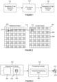
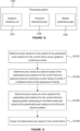
- Figure 1 illustrates an upsampling process for applying upsampling to a sequence of frames.
- a sequence of images 102 which have a relatively low resolution, is processed by a processing module 104 to produce a sequence of images 106 which have a relatively high resolution.
- the processing module 104 may be implemented as a neural network to upsample each of the input images of the sequence of images 102 to produce a respective output image of the sequence of upsampled images 106.
- Implementing the processing module 104 as a neural network may produce good quality output images, but often requires a high performance computing system (e.g. with large, powerful processing units and memories) to implement the neural network.
- processing module 104 may be unsuitable for reasons of processing time, latency, bandwidth, power consumption, memory usage, silicon area and compute costs. These considerations of efficiency are particularly important in some devices, e.g. small, battery operated devices with limited compute and bandwidth resources, such as mobile phones and tablets.
- VSR Video Super-Resolution
- Some systems do not use a neural network for performing super resolution on (sequences of) images, and instead use more conventional processing modules. For example, some systems split the problem of upsampling an image into two stages: (i) upsampling and (ii) adaptive sharpening.
- the upsampling stage can be performed cheaply, e.g. using bilinear upsampling, and the adaptive sharpening stage can be used to sharpen the image, i.e. reduce the blurring introduced by the upsampling.
- Bilinear upsampling is known in the art and uses linear interpolation of adjacent input pixels in two dimensions to produce output pixels at positions between input pixels.
- a method of determining one or more pixel values at a respective one or more upsampled pixel locations for a current frame of a sequence of frames comprising:
- the method may further comprise obtaining pixel values of the one or more identified pixels of the reference frame of the sequence of frames.
- Said determining the pixel value for the upsampled pixel location may comprise performing a weighted sum of the pixel values of the one or more identified pixels of the reference frame using the determined weight for each of the one or more identified pixels in the weighted sum.
- the weight for each of the one or more identified pixels of the reference frame may be determined in dependence on a difference between the depth value of the current frame for the upsampled pixel location and the depth value for the location of the identified pixel of the reference frame.
- the weight for each of the one or more identified pixels of the reference frame may be higher if the difference between the depth value of the current frame for the upsampled pixel location and the depth value for the location of the identified pixel of the reference frame is lower. Similarly, the weight for each of the one or more identified pixels of the reference frame may be lower if the difference between the depth value of the current frame for the upsampled pixel location and the depth value for the location of the identified pixel of the reference frame is higher.
- the method may further comprise, for each of the one or more upsampled pixel locations:
- Said determining a weight for each of the one or more identified pixels of the reference frame may comprise comparing the difference between the depth value of the current frame for the upsampled pixel location and the depth value for the location of the identified pixel of the reference frame with a depth threshold, wherein the depth threshold may be based on the determined standard deviation of the depth values of the current frame within the region.
- the weight for an identified pixel of the reference image may be determined to be lower in response to determining that the difference between the depth value of the current frame for the upsampled pixel location and the depth value for the location of the identified pixel of the reference frame is greater than the depth threshold.
- the depth threshold may be a hard threshold.
- ⁇ T d ), where T d is the depth threshold, where T d F depth ⁇ ⁇ depth , and where w i,k is an initial weight for the identified pixel of the reference image, D ref,k is the depth value for the location of the identified pixel of the reference frame, D curr is the depth value of the current frame for the upsampled pixel location, F depth is a predetermined factor, and ⁇ depth is the determined standard deviation of the depth values of the current frame within the region surrounding the upsampled pixel location.
- the depth threshold may be a soft threshold.
- Said using the motion vector for the upsampled pixel location to identify one or more of the pixels of the reference frame may comprise projecting the upsampled pixel location to a location in the reference frame based on the motion vector and identifying one or more of the pixels of the reference frame in the vicinity of the projected location in the reference frame.
- the initial weight for each of the one or more identified pixels of the reference frame may be determined by:
- the predetermined relationship may be a Gaussian relationship or a linear relationship.
- the weight for each of the one or more identified pixels of the reference frame may be determined in dependence on an extent to which the identified pixel of the reference frame is an outlier compared to the other identified pixels of the reference frame.
- the method may further comprise, for each of the one or more upsampled pixel locations:
- Said determining the pixel value for the upsampled pixel location may comprise clamping the determined pixel value so that it does not differ from the determined mean of the input pixel values of the current frame within the region surrounding the upsampled pixel location by more than a threshold value.
- the method may further comprise, for each of the one or more upsampled pixel locations:
- the threshold value may be F pixel ⁇ ⁇ pixel , where F pixel is a predetermined factor, and ⁇ pixel is the determined standard deviation of the input pixel values of the current frame within the region surrounding the upsampled pixel location.
- the clamping may be applied selectively to different extents to different regions.
- the method may further comprise:
- the pixel value for the upsampled pixel location may be determined to be the determined mean of the input pixel values of the current frame within the region surrounding the upsampled pixel location.
- the upsampled pixel locations may be between the locations of diagonally adjacent input pixels of the current frame, such that the upsampled pixel locations and the locations of the input pixels form a repeating quincunx pattern.
- the resolution of the pixels of the reference frame may be the same as the resolution of input pixels of the current frame.
- a jitter pattern may be used over the sequence of frames, such that different frames of the sequence have pixels at locations corresponding to different upsampled pixel locations.
- the resolution of the pixels of the reference frame may be the same as the resolution of the pixels determined at the upsampled pixel locations.
- the pixel values and the depth values of the current frame and of the reference frame at input pixel locations may be determined by a graphics rendering process.
- Said determining depth weights for said pairs of input pixels may comprise:
- the pixel values may be Y channel pixel values.
- processing module configured to perform any of the methods described herein.
- the processing module may be embodied in hardware on an integrated circuit.
- an integrated circuit definition dataset that, when processed in an integrated circuit manufacturing system, configures the integrated circuit manufacturing system to manufacture a processing module as described herein.
- a method of determining one or more pixel values at a respective one or more upsampled pixel locations for a current frame of a sequence of frames comprising:
- the threshold value may be F pixel ⁇ ⁇ pixel , where F pixel is a predetermined factor, and ⁇ pixel is the determined standard deviation of the input pixel values of the current frame within the region surrounding the upsampled pixel location.
- the clamping may be applied selectively to different extents to different regions.
- the pixel values may be Y channel pixel values.
- said combining the pixel values of the one or more identified pixels of the reference frame may comprise:
- Said determining the pixel value for the upsampled pixel location may comprise performing a weighted sum of the pixel values of the one or more identified pixels of the reference frame using the determined weight for each of the one or more identified pixels in the weighted sum.
- the method may further comprise, for each of the one or more upsampled pixel locations:
- the weight for each of the one or more identified pixels of the reference frame may be determined in dependence on a difference between the depth value of the current frame for the upsampled pixel location and the depth value for the location of the identified pixel of the reference frame.
- the method may further comprise, for each of the one or more upsampled pixel locations:
- Said determining a weight for each of the one or more identified pixels of the reference frame may comprise comparing the difference between the depth value of the current frame for the upsampled pixel location and the depth value for the location of the identified pixel of the reference frame with a depth threshold, wherein the depth threshold is based on the determined standard deviation of the depth values of the current frame within the region.
- the weight for an identified pixel of the reference image may be determined to be lower in response to determining that the difference between the depth value of the current frame for the upsampled pixel location and the depth value for the location of the identified pixel of the reference frame is greater than the depth threshold.
- the depth threshold may be a soft threshold.
- the pixel value for the upsampled pixel location may be determined to be the determined mean of the input pixel values of the current frame within the region surrounding the upsampled pixel location.
- the weight for each of the one or more identified pixels of the reference frame may be determined in dependence on an extent to which the identified pixel of the reference frame is an outlier compared to the other identified pixels of the reference frame.
- Said using the motion vector for the upsampled pixel location to identify one or more of the pixels of the reference frame may comprise projecting the upsampled pixel location to a location in the reference frame based on the motion vector and identifying one or more of the pixels of the reference frame in the vicinity of the projected location in the reference frame.
- said determining a weight for each of the one or more identified pixels of the reference frame may comprise:
- the predetermined relationship may be a Gaussian relationship or a linear relationship.
- the upsampled pixel locations may be between the locations of diagonally adjacent input pixels of the current frame, such that the upsampled pixel locations and the locations of the input pixels form a repeating quincunx pattern.
- the resolution of the pixels of the reference frame may be the same as the resolution of input pixels of the current frame.
- a jitter pattern may be used over the sequence of frames, such that different frames of the sequence have pixels at locations corresponding to different upsampled pixel locations.
- processing module configured to perform any of the methods described herein.
- an integrated circuit definition dataset that, when processed in an integrated circuit manufacturing system, configures the integrated circuit manufacturing system to manufacture a processing module as described herein.
- the upsampled pixel locations of the first and second subsets may form a repeating quincunx pattern.
- the upsampled pixel locations of the third subset may be in the gaps of the repeating quincunx pattern.
- Each of the upsampled pixel locations of the third subset which are not on the edge of the current frame may be either: (i) between two horizontally adjacent upsampled pixel locations of the first subset and between two vertically adjacent upsampled pixel locations of the second subset, or (ii) between two vertically adjacent upsampled pixel locations of the first subset and between two horizontally adjacent upsampled pixel locations of the second subset.
- the first, second and third subsets of upsampled pixel locations may be distinct, such that there are no upsampled pixel locations that belong to more than one of the first, second and third subsets.
- All of the upsampled pixel locations for the current frame may belong to one of the first, second and third subsets.
- a quarter of the upsampled pixel locations for the current frame are in the first subset
- a quarter of the upsampled pixel locations for the current frame are in the second subset
- half of the upsampled pixel locations for the current frame are in the third subset.
- a jitter pattern may be used over the sequence of frames such that pixel values may be determined using a graphics rendering process at different upsampled pixel locations for different frames of the sequence of frames.
- the subset of upsampled pixel locations for which pixel values are determined using a graphics rendering process may alternate for successive frames of the sequence of frames between being the first subset of upsampled pixel locations and being the second subset of upsampled pixel locations.
- the reference frame may be a previous frame or a later frame relative to the current frame in the sequence of frames.
- Said graphics rendering process may be a rasterisation process or a ray tracing process.
- Said determining pixel values at a second subset of the upsampled pixel locations for the current frame by applying temporal resampling to pixel values of pixels of a reference frame of the sequence of frames may comprise:
- Said determining pixel values at a second subset of the upsampled pixel locations for the current frame by applying temporal resampling to pixel values of pixels of a reference frame of the sequence of frames may further comprise:
- Said determining the pixel value for the upsampled pixel location may comprise performing a weighted sum of the pixel values of the one or more identified pixels of the reference frame using the determined weight for each of the one or more identified pixels in the weighted sum.
- the method may further comprise, for each of the one or more upsampled pixel locations of the second subset:
- Said using the motion vector for the upsampled pixel location to identify one or more of the pixels of the reference frame may comprise projecting the upsampled pixel location to a location in the reference frame based on the motion vector and identifying one or more of the pixels of the reference frame in the vicinity of the projected location in the reference frame.
- Said determining pixel values at a third subset of the upsampled pixel locations for the current frame by applying spatial upsampling to the determined pixel values at the upsampled pixel locations of the first and second subsets may comprise performing bilinear interpolation on determined pixel values at the upsampled pixel locations of the first and second subsets.
- the pixel values at the third subset of the upsampled pixel locations may be non-sharpened upsampled pixel values.
- processing system configured to perform any of the methods described herein.
- pixel values can be determined at upsampled pixel locations for a current frame of a sequence of frames using a temporal resampling approach.
- the sequence of frames comprises frames at respective time instances, e.g. the sequence of frames includes the current frame at a current time instance and one or more reference frames each at a respective reference time instance.
- Temporal resampling can be applied to pixel values of pixels of a reference frame of the sequence of frames to determine pixel values at upsampled pixel locations for the current frame.
- the "reference frame" may be a previous frame or a later frame relative to the current frame in the sequence of frames.
- the reference frame is the frame immediately preceding the current frame in the sequence of frames. In some examples there may be a single reference frame, whereas in other examples there may be multiple reference frames.
- the current frame 202 has an input pixel (shown with diagonal hatching) in the top left upsampled pixel location and then in alternate rows and alternate columns from the top left location; whereas the reference frame 204 has an input pixel (shown with diagonal hatching) at an upsampled pixel location in the second-to-top row and in the second-from-left column and then in alternate rows and alternate columns from that location.
- the upsampled pixel locations for which consecutive frames of the sequence have input pixels are shifted relative to each other.
- the jitter pattern may alternate, i.e. the locations of shaded pixels in 202 and 204 may switch from one frame to the next.
- the content represented by frames of a sequence of frames e.g.
- the motion vector has near-zero displacement relative to the location 210 both horizontally and vertically.
- the pixel values of the reference frame can be used to estimate a pixel value at the upsampled pixel location 210, e.g. in accordance with the projected location 214.
- This estimation process is "temporal resampling", and examples for performing temporal resampling are described herein.
- each reference frame may be a previous frame or a later frame relative to the current frame in the sequence of frames.
- Figure 3 shows a processing module 302 configured to apply temporal resampling of a reference frame to obtain pixel values at upsampled pixel locations in a current frame of a sequence of frames 304.
- the sequence of frames 304 includes the current frame 202 and the reference frame 204.
- the reference frame 204 is the frame immediately preceding the current frame 202 in the sequence of frames 304, but in other examples the reference frame could be a different frame, either before or after the current frame in the sequence of frames.
- the processing module 302 comprises temporal resampling logic 306 configured to perform the temporal resampling described herein.
- the temporal resampling logic 306 may be implemented in software, hardware or a combination thereof.
- the human visual system is not as perceptive to spatial resolution in the U and V channels as in the Y channel, so it may be beneficial (e.g. lower power and area cost in a hardware implementation) to use a simpler upsampling technique (e.g. bilinear upsampling on the current frame only) for the U and V channels, whilst the more complex upsampling techniques described herein (which can provide upsampled images with less blurring and/or other artefacts) may be used for the Y channel.
- a simpler upsampling technique e.g. bilinear upsampling on the current frame only
- the more complex upsampling techniques described herein which can provide upsampled images with less blurring and/or other artefacts
- the temporal resampling methods described herein may therefore be applied to the Y channel only, relying on the current frame to furnish the U and V channels, which may increase robustness to chroma errors and reduce implementation cost (for example, reduced bandwidth and execution time in a software implementation of temporal resampling of a GPU),
- the same temporal resampling technique may be applied to all three channels. If the input pixel data is in RGB format then it could be converted into YUV format (e.g. using a known colour space conversion technique) and then processed as data in Y, U and V channels.
- the techniques described herein could be implemented on the R, G and B channels as described herein, wherein the G channel may be considered to be a proxy for the Y channel. If the input data includes an alpha channel then upsampling (e.g. using bilinear interpolation) may be applied to the alpha channel separately.
- Figure 3 shows that for a 2x2 block of upsampled pixel locations 308, the current frame 202 has one pixel value, in the top left of the 2x2 block 308 in the example shown in Figure 3 , and the processing module 302 outputs a block of pixel values 310 which includes a temporally resampled pixel value 312 for the bottom right upsampled pixel location.
- a depth value for a pixel represents a distance from a viewpoint (or "camera centre") for the frame to a visible surface in the scene represented by the pixel in the frame.
- Figure 5 illustrates upsampled pixel locations of the current frame 202, indicating the upsampled pixel locations for which pixel values and/or depth values are obtained.
- the solid circles indicate upsampled pixel locations for which pixel values and depth values are obtained in step S404; and the empty circles indicate upsampled pixel locations for which depth values (but not pixel values) are obtained in step S404.
- pixel values nor depth values are obtained in step S404 for upsampled pixel locations indicated by squares without circles in Figure 5 .
- the pixel values and depth values that are obtained in step S404 may be provided by a graphics rendering process, e.g. implemented by a graphics processing unit and sent to the processing module 302.
- N D 13 because there are thirteen locations for which depth values are obtained within the region 510.
- N D may be different if the region 510 includes a different number of locations for which depth values are obtained.
- step S410 the processing module 302 uses the motion vector 602 for the upsampled pixel location 504 to identify a plurality of the pixels of the reference frame 204.
- the upsampled pixel location 504 is projected to a location 604 in the reference frame 204 based on the motion vector 602, and a plurality of pixels of the reference frame are identified in the vicinity of the projected location in the reference frame.
- the four pixels (606 1 , 606 2 , 606 3 and 606 4 ) of the reference frame 204 that are the closest to the projected location 604 may be identified.
- FIG 4 shows a dashed box representing step S411 in which the processing module 302 combines the pixel values of the identified pixels 606 of the reference frame 204 to determine a pixel value for the upsampled pixel location 504.
- step S411 may involve performing bilinear interpolation of the identified pixels 606 of the reference frame.
- step S411 comprises steps S412 and S414.
- the determination of a weight for an identified pixel 606 in step S412 may be performed in multiple steps. For example, an initial weight for an identified pixel may be determined and then the initial weight may be used (or 'refined') to determine the (final) weight for the identified pixel of the reference frame.
- an initial weight for each of the identified pixels (606 1 to 606 4 ) of the reference frame 204 may be determined by determining a distance between the projected location 604 and the location of the identified pixel 606 in the reference frame 204, and then mapping the distance to an initial weight using a predetermined relationship. The distances are shown with dotted lines in Figure 6 . The distances may be any suitable measure of distance, e.g. L2 distances, squared L2 distances or L1 distances.
- the initial weights may be determined using either linear or non-linear functions, or with machine learning methods (e.g. using a neural network to compute the weights).
- the edge of an object in the scene passes through the region represented by the identified pixels 606 in the reference frame 204, and if all of the identified pixels are weighted equally then the effect will be to introduce blurring into the pixel values across the edge of the object. Since only some of the pixel values of the current frame are determined by temporal resampling, the presence of blurring in these pixel values but not in other pixel values can cause blocky artefacts, such as crenulation, which are very noticeable to a viewer of the images. Furthermore, by taking the depth values into account when determining the weights, the temporal resampling process can exclude occlusions. Rejecting hidden/misprojected samples improves edge definition and handles occlusions.
- a process of history rectification may be used (as described below) to fill in the missing pixel value.
- the depth value of an identified pixel 606 of the reference frame 204 is similar enough to the depth value for the upsampled pixel location 504 of the current frame 202 then that identified pixel 606 can be considered to be representing an adjacent point on the same surface as the upsampled pixel location 504 of the current frame, and can therefore be given a relatively high weight.
- an identified pixel 606 of the reference frame 204 is not similar enough to the depth value for the upsampled pixel location 504 of the current frame 202 then that identified pixel 606 may be considered to be representing a non-adjacent point to that represented by the upsampled pixel location 504 of the current frame, which is indicative of an occlusion boundary being crossed, and can therefore be given a relatively low weight.
- ⁇ T d ), where T d is the depth threshold, where T d F depth ⁇ ⁇ depth , and where w i,k is the initial weight for the identified pixel of the reference image (e.g.
- identified pixels 606 from the previous frame 204 that have significantly different depths to the upsampled pixel location 504 in the current frame 202 are rejected, which avoids (or at least reduces) artefacts that may be caused by blurring over object edges.
- the use of the standard deviation, ⁇ depth makes the threshold, T d , adaptive.
- An advantage of using a soft threshold rather than a hard threshold is that it would help avoid sudden transitions between including and rejecting pixels, which may manifest as temporal artefacts.
- using a soft threshold may also make the algorithm continuously differentiable, which is useful in terms of being able to train the F depth factor.
- the determination of the weights for the identified pixels involves a per-identified-pixel depth test.
- the use of the per-pixel depth tests does not blur object edges, and classifies relevant parts of the reference frame to use for temporal resampling.
- the quality of the temporal resampling of the methods described herein is better than can be achieved with other, known techniques, such as bilinear sampling methods.
- the depth tests described herein are made robust and adaptive in a way that leads to a much higher-quality depth test and thereby improved temporal resampling.
- the threshold comparison could be replaced with a sigmoid function, which would make the solution differentiable, and therefore trainable using known training algorithms, e.g. based on back-propagation of errors.
- the pixel value for the upsampled pixel location 504 may be determined to be equal to the mean of the input pixel values, ⁇ pixel , of the current frame 202 within the region 510 surrounding the upsampled pixel location 504. This can happen frequently in disoccluded regions in the current frame.
- a process of history rectification as described below can be relied upon in this situation.
- step S414 when the weights for the identified pixels have been determined the pixel value for the upsampled pixel location can then be determined using the weights, e.g. by performing a weighted sum.
- a process may be implemented to prevent significant errors by ensuring that the determined pixel value does not differ from the determined mean of the input pixel values, ⁇ pixel , of the current frame 202 (determined in step S406) within the region 510 surrounding the upsampled pixel location 504 by more than a threshold value, T p .
- step S414 may comprise clamping the determined pixel value so that it does not differ from the determined mean of the input pixel values, ⁇ pixel , of the current frame within the region 510 surrounding the upsampled pixel location 504 by more than the threshold value, T p .
- the threshold value, T p may be based on the standard deviation of the input pixel values, ⁇ pixel , of the current frame within the region 510, as determined in step S406.
- the threshold factor, F pixel is a predetermined factor which may be pre-trained.
- the threshold factor, F pixel may have a different value in different implementations, and may be set by a developer. To give an example, F pixel may be 2.
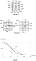
- Figure 8 shows a graph illustrating clamping of the determined pixel value for the upsampled pixel location 504.
- the dashed line 802 represents applying no history rectification, i.e. no clamping, such that the pixel value is unaltered.
- the solid line 804 represents the result of applying history rectification, e.g. applying clamping, to the pixel value. If the (unclamped) pixel value is within a range from ( ⁇ pixel - T p ) to ( ⁇ pixel + T p ) then the history rectification, i.e. the clamping, does not alter the pixel value.
- the clamped pixel value 804 is set to be equal to ( ⁇ pixel - T p ); and if the (unclamped) pixel value is greater than ( ⁇ pixel + T p ) then the clamped pixel value 804 is set to be equal to ( ⁇ pixel + T p ).
- history rectification ensures that the resampled pixel value does not differ by too much from the neighbouring pixel values of the current low resolution image 202.
- History rectification is useful when the appearance at the projected location 604 in the reference frame 204 indicated by the motion vector 602 is not a good match for the appearance of the corresponding location 504 in the current frame 202.
- history rectification is useful when a motion vector is not representative of actual motion between frames, e.g. for transparent objects, transparent overlays or for objects such as fire or mirrors.
- the history rectification method might be applied only on a single channel (the Y channel), and the colour can be filled in from the known-correct U and V values from the current frame, e.g.
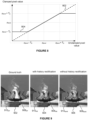
- Figure 9 shows three versions of a portion of an upsampled frame: (i) a ground truth version 902, (ii) a version 904 in which history rectification has been applied to the pixel values, and (iii) a version 906 in which history rectification has not been applied to the pixel values.
- This portion of the upsampled frame includes a rendering of fire.
- a region 908 NHR of the version 906 for which no history rectification is applied includes an image of the fire, and it can be seen that when no history rectification is applied then prominent blocky artefacts are introduced (compared to the corresponding region 908 GT of the ground truth version 902).
- history rectification may not always be beneficial.
- history rectification can sometimes erroneously remove small image features (e.g. lines with a thickness approximately corresponding to the size of one upsampled pixel).
- small image features e.g. lines with a thickness approximately corresponding to the size of one upsampled pixel.
- a region 910 GT of the ground truth version 902 includes a thin dark horizontal line near the top of the region, and it can be seen that this dark line is not present in the corresponding region 910 HR of the version 904 for which history rectification is applied.
- the corresponding region 910 NHR in the version 906 for which no history rectification is applied includes this thin dark line.
- history rectification may be selectively applied to some regions of the image and not to other regions.
- motion vectors will be incorrect or unreliable for an entire region of an image rather than isolated pixels, allowing a method based on local neighbourhood statistics to be used to selectively enable or disable the method, or alternatively to modulate the threshold value T p .
- pixel values may be determined within the region 510 surrounding the upsampled pixel location 504, without performing history rectification.
- the processing module 302 can compare an average of the pixel values determined within the region 510 with the mean of the input pixel values, ⁇ pixel , of the current frame 202 within the region 510.
- the history rectification i.e. the clamping
- history rectification i.e. clamping
- the difference between the average of the pixel values within the region 908 NHR of the version 906 and the mean of the input pixel values, ⁇ pixel , for that region will be large, e.g. greater than the threshold difference (if a suitable threshold difference is used), such that history rectification will be applied to this region such that this region of the upsampled image will look like the region 908 HR of the version 904.
- the difference between the average of the pixel values within the region 910 NHR of the version 906 and the mean of the input pixel values, ⁇ pixel , for that region will be small, e.g. less than the threshold difference (if a suitable threshold difference is used), such that history rectification will not be applied to this region such that this region of the upsampled image will look like the region 910 NHR of the version 906.
- the threshold value may be a soft threshold.
- the clamping can be applied selectively to different extents to different regions.
- an average of pixel values determined at upsampled pixel locations within the region surrounding the upsampled pixel location may be compared with the mean of the input pixel values of the current frame within the region surrounding the upsampled pixel location, and the clamping may be performed in dependence on a comparison of: (i) a difference between the average of pixel values determined at upsampled pixel locations within the region surrounding the upsampled pixel location and the mean of the input pixel values of the current frame within the region surrounding the upsampled pixel location, and (ii) a threshold difference.
- step S416 the processing module 302 determines whether there is another upsampled pixel location for which a pixel value is to be determined. If there is another upsampled pixel location for which a pixel value is to be determined then the method passes from step S416 back to step S406, and steps S406 to S416 are performed to determine a pixel value for the next upsampled pixel location.
- Each of the determined pixel values represents a value of an upsampled pixel at a respective upsampled pixel location which does not correspond with the location of any of the input pixels of the current frame.
- the upsampled pixel locations are between the locations of diagonally adjacent input pixels of the current frame, such that the upsampled pixel locations and the locations of the input pixels form a repeating quincunx pattern.
- spatial upsampling may be performed on the resampled pixels to determine further upsampled pixel values for further upsampled pixels at further upsampled pixel locations between adjacent locations of the repeating quincunx pattern.
- the pixel values at the upsampled pixel locations may be determined in parallel, i.e. the loop in the method shown in Figure 4 does not necessarily imply sequential processing.
- step S416 If it is determined in step S416 that there is not another upsampled pixel location for which a pixel value is to be determined then the method passes from step S416 to step S418.
- step S418 the processing module 302 outputs the determined pixel values for the current frame e.g. for use in implementing a super resolution technique.
- the outputted pixel values may be used in any suitable way, e.g. displayed on a display, stored in a memory or transmitted to another device over a network such as the internet.
- the processing module 302 may go on to determine pixel values for all of the frames of the sequence of frames 304.
- a more general example method for determining weights for combining pixel values 606 from the reference frame 204 for determining the pixel value at the upsampled pixel location 504 of the current frame 202 is now described with reference to Figure 10 .
- the pixel location 504 of the current frame is projected to a location 604 in the reference frame 204.
- a set of (e.g. four pixels) of the reference frame e.g. pixels 606 1 , 606 2 , 606 3 and 606 4 surrounding the projected location 604
- the vicinity, ⁇ may include a different number of pixels of the reference frame, e.g.
- the vicinity, ⁇ could include a 1x1, 2x1, 1 ⁇ 2 or 2x2 set of pixels within a box centred on the projected pixel location 604.
- the temporally resampled pixel value at the upsampled pixel location 504 may be determined as a linear combination of the pixel values 606 in the vicinity, ⁇ , of the reprojected pixel location 604 in the reference frame 204.
- a fall-back spatial interpolation algorithm may be used.
- the upsampled pixel value may be determined to be equal to the mean of the neighbouring input pixel values of the current frame.
- the weights may be considered a representation of the reliability of a given reference pixel 606 in determining the reprojected pixel value. Aspects which may reduce the reliability of a reference pixel 606, which may result in the use of a smaller corresponding weight for that reference pixel, would include:
- aspects iii and iv in the list given in the preceding paragraph determine the weights for the respective reference pixels 606 in dependence on whether that reference pixel is an outlier compared to the other pixels in the vicinity ⁇ of the reference frame.
- the weight for each of the identified pixels of the reference frame i.e. for each of the reference pixels 606 in the vicinity ⁇
- a reference pixel 606 may be an outlier in terms of its pixel value or its depth value.
- a graphics rendering process determines a depth value for the current frame 202 at each of the pixel locations of the current frame (e.g. as denoted with the solid circles 506 in Figure 5 ) and at each of the locations denoted 504 and 508 in Figure 5 which are between diagonally adjacent input pixel locations of the current frame. Therefore, in these examples, the graphics rendering process determines depth values at twice as many locations as it determines pixel values. For example, in a first render pass a graphics processing unit may determine pixel values and depth values at the input pixel locations 506 for a current frame 202, and then in a second render pass the graphics processing unit may determine the depth values at the locations 504 and 508.
- Figure 14 shows the pixel values which are rendered by the graphics processing unit 1204 with diagonal hatching (e.g. pixel 1406 in the current frame 1402, and pixel 1408 in the reference frame 1404).
- the squares of the current frame 1402 and of the reference frame 1404 which are shown without hatching in Figure 14 are upsampled pixel locations for which the graphics processing unit 1204 does not render pixel values.
- the graphics processing unit 1204 renders pixel values for a quarter of the upsampled pixel locations, and the rendered pixel values are evenly distributed throughout the frame, such that for each 2x2 block of upsampled pixel locations there is one rendered pixel value and three upsampled pixel locations for which pixel values are not rendered by the graphics processing unit.
- a 2x2 block of upsampled pixel locations there is one location from the first subset (shown with upwards diagonal hatching), one location from the second subset (shown with downwards diagonal hatching) and two locations from the third subset (shown with diagonal cross-hatching).
- the two locations from the third subset are diagonally opposite each other in the 2x2 block.
- a quarter of the upsampled pixel locations for the current frame are in the first subset
- a quarter of the upsampled pixel locations for the current frame are in the second subset
- half of the upsampled pixel locations for the current frame are in the third subset.
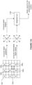
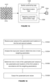
- Figure 15 shows the spatial upsampling logic 1208 configured to apply upsampling to pixel values 1410, which represent an image region, to determine a block of upsampled pixel values 1504, e.g. for use in implementing a super resolution technique.
- the block of upsampled pixel values 1504 represents a location within the image region indicated with the square 1510 in Figure 15 .
- the pixel values 1410 that are received by the spatial upsampling logic 1208 have locations corresponding to a 10x10 block of upsampled pixel locations, and the block of upsampled pixel values 1504 is a 2x2 block of upsampled pixels representing the central 2x2 portion of the 10x10 block of upsampled pixel locations.
- the spatial upsampling logic 1208 may perform upsampling which is dependent upon relative horizontal and vertical variation of the pixel values 1410 within the image region.
- the upsampling takes account of anisotropic features (e.g. edges) in the image, to reduce 'staircasing' and 'crenulation' artefacts and blurring that can occur near anisotropic features (e.g. edges, particularly diagonal edges of computer-generated images), compared to the case where bilinear upsampling is used.
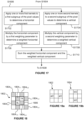
- a method of using the spatial upsampling logic 1208 to apply upsampling to the pixel values 1410 to determine the block of upsampled pixel values 1504, e.g. for use in implementing a super resolution technique, is described with reference to the flow chart of Figure 16 .
- step S1602 the pixel values 1410 at the upsampled pixel locations of the first and second subsets are received at the spatial upsampling logic 1208.
- the pixel values 1410 of the first and second subsets of upsampled pixel locations have locations corresponding to a repeating quincunx arrangement (or 'chequer board pattern') of upsampled pixel locations.
- the first subset of upsampled pixel locations corresponds to locations within odd rows of the repeating quincunx arrangement of upsampled pixel locations
- the second subset of upsampled pixel locations corresponds to locations within even rows of the repeating quincunx arrangement of upsampled pixel locations.
- the weighting parameter determination logic 1508 analyses the pixel values 1410 at the upsampled pixel locations of the first and second subsets to determine one or more weighting parameters.
- the one or more weighting parameters are indicative of a directionality of filtering to be applied when upsampling is applied to the determined pixel values at the upsampled pixel locations of the first and second subsets.
- the one or more weighting parameters may be indicative of relative horizontal and vertical variation of the pixel values 1410 at the upsampled pixel locations of the first and second subsets.
- the weighting parameters may be referred to as directional weighting parameters.
- two weighting parameters ( a and b ) may be determined in step S1604.
- step S1608 the block of upsampled pixel values 1504 is output from the pixel determination logic 1506. In some systems this could be the end of the processing on the block of upsampled pixel values 1504 and it could be output from the spatial upsampling logic 1208 (and maybe from the processing system 1202) as shown in Figure 15 . In other examples, adaptive sharpening may be applied to the upsampled pixel values (e.g. by blending with sharpened upsampled pixel values) before they are output from the spatial upsampling logic 1208.
- Each of the upsampled pixel values that is determined in accordance with the relative horizontal and vertical variation of the pixel values 1410 at the upsampled pixel locations of the first and second subsets, in step S1606, is at a respective upsampled pixel location of the third subset (and not of the first or second subsets).
- the top right and the bottom left upsampled pixel value in the block of upsampled pixel values are determined in step S1606 in accordance with the relative horizontal and vertical variation of the pixel values 1410 at the upsampled pixel locations of the first and second subsets.
- the input pixel values having locations (of the first and second subsets) corresponding to the repeating quincunx arrangement of upsampled pixel locations are used as the upsampled pixel values at those upsampled pixel locations of the block of upsampled pixel values (e.g. the pixel values at the top left and bottom right locations of the block of upsampled pixel values 1806 are "passed through" to the corresponding locations in the output block). If sharpening is applied then some processing may be performed on the input pixel values to determine all of the upsampled pixel values in the block of upsampled pixel values.
- the input pixel values 1804 are at locations of the first and second subsets.
- input pixel values 1804 1,1 , 1804 1,2 , 1804 1,3 and 1804 1,4 which are shown with upwards diagonal line hatching, are at upsampled pixel locations of the first subset; whereas input pixel values 1804 2,1 , 1804 2,2 , 1804 2,3 and 1804 2,4 , which are shown with downwards diagonal line hatching, are at upsampled pixel locations of the second subset.
- step S1606 of determining each of said one or more of the upsampled pixel values at the third subset of upsampled pixel locations comprises applying one or more kernels to at least some of the pixel values at the upsampled pixel locations of the first and second subsets in accordance with the determined one or more weighting parameters.
- the pixel determination logic 1506 applies one or more first kernels (which may be referred to as horizontal kernels) to at least a first subgroup of the input pixel values 1804 to determine a horizontal component.
- a kernel of [0.5,0.5] can be applied to the input pixel values which are horizontally adjacent and either side of the upsampled pixel location for which an upsampled pixel value is being determined.
- the horizontal kernel is applied to pixel values 1804 1,1 and 1804 1,2 at upsampled pixel locations of the first subset.
- the horizontal kernel is applied to pixel values 1804 2,3 and 1804 2,4 at upsampled pixel locations of the second subset.
- step S1704 the pixel determination logic 1506 applies one or more second kernels (which may be referred to as vertical kernels) to at least a second subset of the input pixel values 1804 to determine a vertical component.
- a kernel of 0.5 0.5 can be applied to the input pixel values which are vertically adjacent and either side of the upsampled pixel location for which an upsampled pixel value is being determined.
- the vertical kernel is applied to pixel values 1804 2,2 and 1804 2,4 at upsampled pixel locations of the second subset.
- step S1704 is performed for the upsampled pixel value denoted "BL” in Figure 18 then the vertical kernel is applied to pixel values 1804 1,1 and 1804 1,3 at upsampled pixel locations of the first subset.
- each of the one or more of the upsampled pixel locations of the third subset, for which step S1606 is performed has two horizontally adjacent pixel values which are both at locations of the same subset (either from the first subset or the second subset) and has two vertically adjacent pixels which are both at locations of the other of the first and second subsets (either from the second subset or the first subset).
- steps S1702 and S1704 may be performed in any order, e.g. sequentially, or may be performed in parallel.
- the pixel determination logic 1506 combines the determined horizontal and vertical components, such that each of said one or more of the upsampled pixel values is determined in accordance with the relative horizontal and vertical variation of the pixel values 1410 at the upsampled pixel locations of the first and second subsets as indicated by the one or more weighting parameters determined in step S1604.
- the pixel determination logic 1506 multiplies the horizontal component (determined in step S1702) by a first of the weighting parameters, a, to determine a weighted horizontal component.
- step S1708 the pixel determination logic 1506 multiplies the vertical component (determined in step S1704) by a second of the weighting parameters, b, to determine a weighted vertical component.
- Steps S1706 and S1708 may be performed in any order, e.g. sequentially, or may be performed in parallel.
- step S1710 the pixel determination logic 1506 sums the weighted horizontal component and the weighted vertical component to determine the upsampled pixel value.
- the kernels applied in S1702 and S1704 may be multiplied by the first and second weighting parameters respectively before, or during, application to the input pixel values. This is expected to be less power- and area-efficient in hardware than the method described with reference to Figure 17 , since the application of kernels of Figures 19a and 19b may be obtained using only cheap fixed bit shifts and additions, and the number of variable multiplies required is considerably lower.
- Figure 19a shows a 3x3 kernel 1902 (which may be implemented as a 1x3 kernel) which can be applied to the input pixel values 1802 to represent the effect of performing steps S1702 and S1706 for an upsampled pixel location for which an upsampled pixel value is being determined.
- the kernel 1902 could be centred on the upsampled pixel location for which a value is being determined and applied to the input pixel values 1802 such that the result would be given by the dot product a 2 a 2 . h , where h is a vector of the horizontally adjacent pixel values.
- h [ p 1,1, p 1,2 ], where p 1,1 is the value of input pixel 1804 1,1 and p 1,2 is the value of input pixel 1804 1,2 .
- h [ p 2,3 , p 2,4 ], where p 2 ,3 is the value of input pixel 1804 2,3 and p 2,4 is the value of input pixel 1804 2,4 .
- Figure 19b shows a 3x3 kernel 1904 (which may be implemented as a 3x1 kernel) which can be applied to the input pixels 1802 to represent the effect of performing steps S1704 and S1708 for an upsampled pixel location for which an upsampled pixel value is being determined.
- the kernel 1904 could be centred on the upsampled pixel location for which a value is being determined and applied to the input pixels 1802 such that the result would be given by the dot product b 2 b 2 .
- v where v is a vector of the vertically adjacent pixel values.
- v [ p 2,2 , p 2,4 ], where p 2,2 is the value of input pixel 1804 2,2 and p 2,4 is the value of input pixel 1804 2,4 .
- v [ p 1,1 , p 1,3 ], where p 1,1 is the value of input pixel 1804 1,1 and p 1,3 is the value of input pixel 1804 1,3 .
- steps S1702 to S1710 can be summarised as determining the upsampled pixel values denoted TR and BL as the sum of dot products: a 2 a 2 . h + b 2 b 2 . v , where h and v are vectors of adjacent pixel values as described above for the TR and BL pixels respectively.
- the values of the weighting parameters, a and b may be set in dependence on the local context, such that by determining the upsampled pixel values in step S1606 in accordance with the determined weighting parameters the upsampled pixel values are determined in accordance with the relative horizontal and vertical variation of the pixel values of the first and second subsets.
- the weighting parameters can be used to reduce artefacts and blurring over anisotropic features (e.g. edges) in the image, which may otherwise result from an upsampling process.
- the weighting parameter determination logic 408 analyses the input pixels in step S1604 to determine the one or more weighting parameters.
- the one or more weighting parameters are determined for the particular image region being processed, such that different weighting parameters can be used in the upsampling process for different image regions.
- the weighting parameters can be adapted to suit the particular local context of the image region for which upsampled pixel values are being determined. This allows suitable weighting parameters to be used for different image regions based on the different anisotropic image features present in the different image regions.
- the spatial upsampling logic 1208 may or may not be configured to apply sharpening as well as spatial upsampling.
- the pixel values at the third subset of the upsampled pixel locations are non-sharpened upsampled pixel values; whereas in some other examples, the pixel values at the third subset of the upsampled pixel locations are sharpened upsampled pixel values.
- Techniques for applying sharpening are known in the art, and as such are not described in detail herein.
- the reference frame(s) are low resolution images, with pixel values at the same resolution as the input pixel values of the current frame.
- the techniques can be adapted to operate in an accordance with an 'Infinite Impulse Response (IIR)' technique.
- the reference frame(s) may be high resolution images which are the result of applying the upsampling technique to the reference frame, and which have pixel values at the same resolution as the output (i.e. upsampled) pixel values of the current frame.
- a feedback loop may be introduced so that the output of the spatial algorithm for a previous frame can be used as the reference frame for the temporal resampling process performed for the current frame.
- Including this feedback loop might make the system more complicated and expensive (e.g. in terms of power, bandwidth and GPU SRAM use) to implement, but it may increase the quality of the output images.
- the components of the processing system 1202 may or may not be implemented within the same device.
- the processing system 1202 may be implemented as a distributed system (e.g. a "client/server system").
- the processing system may comprise a first device and a second device which are arranged to communicate with each other over a network.
- the graphics rendering unit 1204 and the temporal resampling logic 1206 may be implemented at the first device (e.g. a server), and the spatial upsampling logic 1208 may be implemented at the second device (e.g. a client, which may for example be a mobile device).
- the server side is responsible for producing the rendered and temporally resampled pixels
- the client side is responsible for spatial upsampling.
- the client and the server may be in physically separate locations, but can communicate with each other over a network, e.g. over the internet, over a wired connection, and/or over a wireless connection such as a WiFi or Bluetooth connection.
- the client which may be implemented at a mobile device (e.g. a handheld, battery-powered device) generally has tighter constraints (in terms of factors such as power consumption, physical size, etc.) than the server, which is typically not implemented as a mobile device.
- Implementing the different components of the processing system 1202 at different devices, e.g. in a client/server system as described above, may be advantageous for one or more of the following reasons:
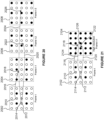
- FIG. 20 illustrates pixel values of a sequence of frames indicating how upsampled pixel locations can be projected to locations in reference frames according to an example implementing a "Finite Impulse Response" (FIR) approach.
- FIR Finite Impulse Response
- the term FIR is used by analogy to FIR filtering in signal processing applications, which combine signal values from multiple time instances in a non-recursive fashion to yield a filtered output for a current time instance.
- the current frame 2002 is denoted "Frame t" in Figure 20 , and there are three reference frames: “Frame t-1" 2004, “Frame t-2" 2006 and “Frame t-3” 2008.
- the graphics rendering unit For each of the frames, the graphics rendering unit renders a quarter of the upsampled pixel values, e.g. it renders the pixel values at the first subset of the upsampled pixel locations as described above.
- the rendered pixel values are represented with solid circles in Figure 20 .
- temporal resampling is used to determine the upsampled pixel values for the other three quarters of the upsampled pixel locations of the current frame 2002 (which are shown as empty circles or circles with hatching in Figure 20 ).
- the set of locations at which the graphics rendering unit renders the pixel values is jittered over the sequence of frames, and in particular, so that over a sequence of four frames a pixel value is rendered by the graphics rendering unit at all of the upsampled pixel locations.
- a jitter pattern is used over the sequence of frames, such that different frames of the sequence have pixels at locations corresponding to different upsampled pixel locations. Therefore, if the camera (i.e. a viewpoint) is static then all of the high resolution pixel locations are rendered once during a sequence of four frames in this example.
- Figure 20 illustrates how three of the upsampled pixel values (2010, 2012 and 2014) can be determined using temporal resampling.
- a motion vector is obtained which can be used to project that upsampled pixel location to a projected location in one reference frame (in particular, the reference frame for which the graphics rendering unit rendered a pixel value at the corresponding upsampled pixel location).
- the temporal resampling technique can then proceed for each of the upsampled pixel locations (2010, 2012 and 2014) as described above with reference to Figure 4 using the pixel values of the respective reference frame to which the locations of the upsampled pixel locations have been projected.
- temporal resampling logic can determine the upsampled pixel values at the locations 2010, 2012 and 2014 based on three low resolution reference frames.
- a motion vector 2116 is used to project the upsampled pixel location 2110 of the current frame 2102 to a projected location 2118 of the reference frame 2104;
- a motion vector 2120 is used to project the upsampled pixel location 2112 of the current frame 2102 to a projected location 2122 of the reference frame 2104;
- a motion vector 2124 is used to project the upsampled pixel location 2114 of the current frame 2102 to a projected location 2126 of the reference frame 2104.
- some of the motion vectors may be upsampled/interpolated from a low-resolution motion vector field.
- temporal resampling technique can then proceed for each of the upsampled pixel locations (2110, 2112 and 2114) as described above with reference to Figure 4 using the pixel values of the reference frame 2104.
- temporal resampling logic can determine the upsampled pixel values at the locations 2110, 2112 and 2114 based on one high resolution reference frame.
- the IIR approach (described with reference to Figure 21 ) has some advantages over the FIR approach (described with reference to Figure 20 ). For example, in the IIR approach the pixels of the reference frame are closer together so the distances between the projected location and the identified pixels in the reference frame (which are used to determine the weights for combining the identified pixels for determining the pixel value at the upsampled pixel location) are smaller than in the FIR approach. Having smaller distances tends to mean that the values of the identified pixels are a better approximation for the pixel value at the upsampled pixel location. However, the IIR approach also has some disadvantages over the FIR approach.
- depth values and pixel values are obtained for the reference frame and for the current frame in steps S402 and S404. In other examples, fewer than all four of these four things could be obtained. For example, if history rectification is not implemented, or if depth values are not used to determine the weights then the temporal resampling logic might not need to obtain all of these things. Similarly, in some examples it might not be necessary to determine the mean and the standard deviation of the pixel values and of the depth values for the region 510 of the current frame in step S406.
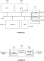
- FIG 22 shows a computer system in which the processing modules or processing systems described herein may be implemented.
- the computer system comprises a CPU 2202, a GPU 2204, a memory 2206, a neural network accelerator (NNA) 2208 and other devices 2214, such as a display 2216, speakers 2218 and a camera 2222.
- a processing block 2210 (corresponding to the processing modules described herein) is implemented on the GPU 2204. In other examples, one or more of the depicted components may be omitted from the system, and/or the processing block 2210 may be implemented on the CPU 2202 or within the NNA 2208 or in a separate block in the computer system.
- the components of the computer system can communicate with each other via a communications bus 2220.
- the GPU 2204 may correspond to the graphics rendering unit 1204.
- processing modules and processing systems described herein are shown as comprising a number of functional blocks. This is schematic only and is not intended to define a strict division between different logic elements of such entities. Each functional block may be provided in any suitable manner. It is to be understood that intermediate values described herein as being formed by a processing module or a processing system need not be physically generated by the processing module or processing system at any point and may merely represent logical values which conveniently describe the processing performed by the processing module or processing system between its input and output.
- the processing modules and processing systems described herein may be embodied in hardware on an integrated circuit.
- the processing modules or processing systems described herein may be configured to perform any of the methods described herein.
- any of the functions, methods, techniques or components described above can be implemented in software, firmware, hardware (e.g., fixed logic circuitry), or any combination thereof.
- the terms “module,” “functionality,” “component”, “element”, “unit”, “block” and “logic” may be used herein to generally represent software, firmware, hardware, or any combination thereof.
- the module, functionality, component, element, unit, block or logic represents program code that performs the specified tasks when executed on a processor.
- a computer-readable storage medium examples include a random-access memory (RAM), read-only memory (ROM), an optical disc, flash memory, hard disk memory, and other memory devices that may use magnetic, optical, and other techniques to store instructions or other data and that can be accessed by a machine.
- RAM random-access memory
- ROM read-only memory
- optical disc optical disc
- flash memory hard disk memory
- hard disk memory and other memory devices that may use magnetic, optical, and other techniques to store instructions or other data and that can be accessed by a machine.
- Computer program code and computer readable instructions refer to any kind of executable code for processors, including code expressed in a machine language, an interpreted language or a scripting language.
- Executable code includes binary code, machine code, bytecode, code defining an integrated circuit (such as a hardware description language or netlist), and code expressed in a programming language code such as C, Java or OpenCL.
- Executable code may be, for example, any kind of software, firmware, script, module or library which, when suitably executed, processed, interpreted, compiled, executed at a virtual machine or other software environment, cause a processor of the computer system at which the executable code is supported to perform the tasks specified by the code.
- a processor, computer, or computer system may be any kind of device, machine or dedicated circuit, or collection or portion thereof, with processing capability such that it can execute instructions.
- a processor may be or comprise any kind of general purpose or dedicated processor, such as a CPU, GPU, NNA, System-on-chip, state machine, media processor, an application-specific integrated circuit (ASIC), a programmable logic array, a field-programmable gate array (FPGA), or the like.
- a computer or computer system may comprise one or more processors.
- An integrated circuit definition dataset may be in the form of computer code, for example as a netlist, code for configuring a programmable chip, as a hardware description language defining hardware suitable for manufacture in an integrated circuit at any level, including as register transfer level (RTL) code, as high-level circuit representations such as Verilog or VHDL, and as low-level circuit representations such as OASIS (RTM) and GDSII.
- RTL register transfer level
- RTM high-level circuit representations
- GDSII GDSI
- one or more intermediate user steps may be required in order for a computer system configured for generating a manufacturing definition of an integrated circuit to execute code defining an integrated circuit so as to generate the manufacturing definition of that integrated circuit.
- Figure 23 shows an example of an integrated circuit (IC) manufacturing system 2302 which is configured to manufacture a processing module or processing system as described in any of the examples herein.
- the IC manufacturing system 2302 comprises a layout processing system 2304 and an integrated circuit generation system 2306.
- the IC manufacturing system 2302 is configured to receive an IC definition dataset (e.g. defining a processing module or processing system as described in any of the examples herein), process the IC definition dataset, and generate an IC according to the IC definition dataset (e.g. which embodies a processing module or processing system as described in any of the examples herein).
- the processing of the IC definition dataset configures the IC manufacturing system 2302 to manufacture an integrated circuit embodying a processing module or processing system as described in any of the examples herein.
- the layout processing system 2304 is configured to receive and process the IC definition dataset to determine a circuit layout.
- Methods of determining a circuit layout from an IC definition dataset are known in the art, and for example may involve synthesising RTL code to determine a gate level representation of a circuit to be generated, e.g. in terms of logical components (e.g. NAND, NOR, AND, OR, MUX and FLIP-FLOP components).
- a circuit layout can be determined from the gate level representation of the circuit by determining positional information for the logical components. This may be done automatically or with user involvement in order to optimise the circuit layout.
- the layout processing system 2304 may output a circuit layout definition to the IC generation system 2306.
- a circuit layout definition may be, for example, a circuit layout description.
- the IC generation system 2306 generates an IC according to the circuit layout definition, as is known in the art.
- the IC generation system 2306 may implement a semiconductor device fabrication process to generate the IC, which may involve a multiple-step sequence of photo lithographic and chemical processing steps during which electronic circuits are gradually created on a wafer made of semiconducting material.
- the circuit layout definition may be in the form of a mask which can be used in a lithographic process for generating an IC according to the circuit definition.
- the circuit layout definition provided to the IC generation system 2306 may be in the form of computer-readable code which the IC generation system 2306 can use to form a suitable mask for use in generating an IC.
- the different processes performed by the IC manufacturing system 2302 may be implemented all in one location, e.g. by one party.
- the IC manufacturing system 2302 may be a distributed system such that some of the processes may be performed at different locations, and may be performed by different parties.
- some of the stages of: (i) synthesising RTL code representing the IC definition dataset to form a gate level representation of a circuit to be generated, (ii) generating a circuit layout based on the gate level representation, (iii) forming a mask in accordance with the circuit layout, and (iv) fabricating an integrated circuit using the mask may be performed in different locations and/or by different parties.
- processing of the integrated circuit definition dataset at an integrated circuit manufacturing system may configure the system to manufacture a processing module or processing system without the IC definition dataset being processed so as to determine a circuit layout.
- an integrated circuit definition dataset may define the configuration of a reconfigurable processor, such as an FPGA, and the processing of that dataset may configure an IC manufacturing system to generate a reconfigurable processor having that defined configuration (e.g. by loading configuration data to the FPGA).
- an integrated circuit manufacturing definition dataset when processed in an integrated circuit manufacturing system, may cause an integrated circuit manufacturing system to generate a device as described herein.
- the configuration of an integrated circuit manufacturing system in the manner described above with respect to Figure 23 by an integrated circuit manufacturing definition dataset may cause a device as described herein to be manufactured.
- an integrated circuit definition dataset could include software which runs on hardware defined at the dataset or in combination with hardware defined at the dataset.
- the IC generation system may further be configured by an integrated circuit definition dataset to, on manufacturing an integrated circuit, load firmware onto that integrated circuit in accordance with program code defined at the integrated circuit definition dataset or otherwise provide program code with the integrated circuit for use with the integrated circuit.
- performance improvements may include one or more of increased computational performance, reduced latency, increased throughput, and/or reduced power consumption.
- performance improvements can be traded-off against the physical implementation, thereby improving the method of manufacture. For example, a performance improvement may be traded against layout area, thereby matching the performance of a known implementation but using less silicon. This may be done, for example, by reusing functional blocks in a serialised fashion or sharing functional blocks between elements of the devices, apparatus, modules and/or systems.
Landscapes
- Engineering & Computer Science (AREA)
- Theoretical Computer Science (AREA)
- Physics & Mathematics (AREA)
- General Physics & Mathematics (AREA)
- Computer Vision & Pattern Recognition (AREA)
- Multimedia (AREA)
- Evolutionary Computation (AREA)
- Artificial Intelligence (AREA)
- Computing Systems (AREA)
- Databases & Information Systems (AREA)
- Health & Medical Sciences (AREA)
- General Health & Medical Sciences (AREA)
- Medical Informatics (AREA)
- Software Systems (AREA)
- Image Processing (AREA)
- Image Analysis (AREA)
Applications Claiming Priority (1)
| Application Number | Priority Date | Filing Date | Title |
|---|---|---|---|
| GB2319652.0A GB2636744B (en) | 2023-12-20 | 2023-12-20 | Upsampling |
Publications (1)
| Publication Number | Publication Date |
|---|---|
| EP4575978A1 true EP4575978A1 (fr) | 2025-06-25 |
Family
ID=89662580
Family Applications (2)
| Application Number | Title | Priority Date | Filing Date |
|---|---|---|---|
| EP24220689.4A Pending EP4575977A1 (fr) | 2023-12-20 | 2024-12-17 | Suréchantillonnage |
| EP24220695.1A Pending EP4575978A1 (fr) | 2023-12-20 | 2024-12-17 | Suréchantillonnage |
Family Applications Before (1)
| Application Number | Title | Priority Date | Filing Date |
|---|---|---|---|
| EP24220689.4A Pending EP4575977A1 (fr) | 2023-12-20 | 2024-12-17 | Suréchantillonnage |
Country Status (4)
| Country | Link |
|---|---|
| US (1) | US20250322640A1 (fr) |
| EP (2) | EP4575977A1 (fr) |
| CN (1) | CN120182089A (fr) |
| GB (2) | GB2644366A (fr) |
Citations (4)
| Publication number | Priority date | Publication date | Assignee | Title |
|---|---|---|---|---|
| US20230138718A1 (en) * | 2021-10-29 | 2023-05-04 | Nvidia Corporation | Illumination resampling using temporal gradients in light transport simulation systems and applications |
| US20230143192A1 (en) * | 2021-11-05 | 2023-05-11 | Intel Corporation | Input filtering and sampler acceleration for supersampling |
| US20230298212A1 (en) * | 2022-03-17 | 2023-09-21 | Advanced Micro Devices, Inc. | Locking mechanism for image classification |
| US20230298133A1 (en) * | 2022-03-17 | 2023-09-21 | Advanced Micro Devices, Inc. | Super resolution upscaling |
Family Cites Families (3)
| Publication number | Priority date | Publication date | Assignee | Title |
|---|---|---|---|---|
| GB2319652B (en) | 1996-11-26 | 2001-05-09 | Skyinbow Ltd | Electrical musical instrument |
| US11216916B1 (en) * | 2020-10-09 | 2022-01-04 | Nvidia Corporation | History clamping for denoising dynamic ray-traced scenes using temporal accumulation |
| CN119032575A (zh) * | 2022-04-15 | 2024-11-26 | 现代自动车株式会社 | 使用用于色度分量的改进环内滤波器的视频编码方法和装置 |
-
2023
- 2023-12-20 GB GB2520690.5A patent/GB2644366A/en active Pending
- 2023-12-20 GB GB2319652.0A patent/GB2636744B/en active Active
-
2024
- 2024-12-17 EP EP24220689.4A patent/EP4575977A1/fr active Pending
- 2024-12-17 EP EP24220695.1A patent/EP4575978A1/fr active Pending
- 2024-12-18 CN CN202411869826.1A patent/CN120182089A/zh active Pending
- 2024-12-20 US US18/989,805 patent/US20250322640A1/en active Pending
Patent Citations (4)
| Publication number | Priority date | Publication date | Assignee | Title |
|---|---|---|---|---|
| US20230138718A1 (en) * | 2021-10-29 | 2023-05-04 | Nvidia Corporation | Illumination resampling using temporal gradients in light transport simulation systems and applications |
| US20230143192A1 (en) * | 2021-11-05 | 2023-05-11 | Intel Corporation | Input filtering and sampler acceleration for supersampling |
| US20230298212A1 (en) * | 2022-03-17 | 2023-09-21 | Advanced Micro Devices, Inc. | Locking mechanism for image classification |
| US20230298133A1 (en) * | 2022-03-17 | 2023-09-21 | Advanced Micro Devices, Inc. | Super resolution upscaling |
Also Published As
| Publication number | Publication date |
|---|---|
| CN120182089A (zh) | 2025-06-20 |
| US20250322640A1 (en) | 2025-10-16 |
| GB202319652D0 (en) | 2024-01-31 |
| GB2636744B (en) | 2026-03-11 |
| GB2644366A (en) | 2026-04-01 |
| EP4575977A1 (fr) | 2025-06-25 |
| GB2636744A (en) | 2025-07-02 |
Similar Documents
| Publication | Publication Date | Title |
|---|---|---|
| EP2074586B1 (fr) | Amélioration d'image | |
| EP3696769B1 (fr) | Filtrage d'images sur la base de gradients d'image | |
| EP1622393B1 (fr) | Interpolation de couleurs en utilisant la triangulation dépendant des données | |
| US8705867B2 (en) | Devices and methods for processing images using scale space | |
| EP2130175B1 (fr) | Mappage de bord incorporant des pixels panchromatiques | |
| EP2018626B1 (fr) | Suréchantillonnage | |
| KR100860968B1 (ko) | 해상도 향상 장치 및 방법 | |
| CN117830145A (zh) | 像素块的自适应锐化 | |
| US20130114892A1 (en) | Method and device for generating a super-resolution image portion | |
| CN117830146A (zh) | 像素块的自适应锐化 | |
| EP4575978A1 (fr) | Suréchantillonnage | |
| EP4345734A1 (fr) | Affinage adaptatif pour blocs de pixels sur-échantillonnés | |
| US20130300890A1 (en) | Image processing apparatus, image processing method, and program | |
| EP4675550A1 (fr) | Suréchantillonnage | |
| GB2623071A (en) | Adaptive sharpening for blocks of pixels | |
| CN117217987A (zh) | 图像处理方法、装置、设备及系统 | |
| CN115311145A (zh) | 图像处理方法及装置、电子设备、存储介质 | |
| US20250322490A1 (en) | Weighting parameters for use in applying upsampling | |
| EP4345740A1 (fr) | Affinage adaptatif pour blocs de pixels | |
| EP4575974A1 (fr) | Suréchantillonnage | |
| Ousguine et al. | A new image interpolation using laplacian operator |
Legal Events
| Date | Code | Title | Description |
|---|---|---|---|
| PUAI | Public reference made under article 153(3) epc to a published international application that has entered the european phase |
Free format text: ORIGINAL CODE: 0009012 |
|
| STAA | Information on the status of an ep patent application or granted ep patent |
Free format text: STATUS: THE APPLICATION HAS BEEN PUBLISHED |
|
| AK | Designated contracting states |
Kind code of ref document: A1 Designated state(s): AL AT BE BG CH CY CZ DE DK EE ES FI FR GB GR HR HU IE IS IT LI LT LU LV MC ME MK MT NL NO PL PT RO RS SE SI SK SM TR |
|
| P01 | Opt-out of the competence of the unified patent court (upc) registered |
Free format text: CASE NUMBER: APP_31311/2025 Effective date: 20250630 |
|
| STAA | Information on the status of an ep patent application or granted ep patent |
Free format text: STATUS: REQUEST FOR EXAMINATION WAS MADE |
|
| 17P | Request for examination filed |
Effective date: 20251219 |